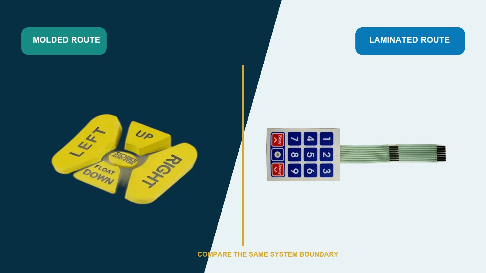
Choose a silicone keypad when the product needs a molded three-dimensional key surface, a deliberately shaped press response, positive finger location, or an elastomer component that participates in the enclosure interface. Choose a membrane keypad when the dominant requirements are a thin laminated control surface, integrated graphics and circuitry, fast artwork variation, or a flat wipeable face. This engineering selection memo is for OEM mechanical, electrical, industrial-design, quality, and sourcing teams. It compares both architectures under the same operator, enclosure, circuit, environment, validation, quantity, and service assumptions rather than comparing a loose rubber part with a complete membrane assembly.
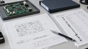
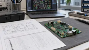
For a fair sourcing review, place JASPER’s custom silicone rubber keypads and membrane keypads on one input sheet. The quote boundary must say whether each option includes only the user-contact part, the switching circuit, graphics, lighting, adhesive, connector, support, enclosure interface, assembly, and functional verification. A low part price is not a low system price when the missing layers move to another supplier or to the OEM assembly line.
Decision Record
Decision status: conditional until the installed stack, change forecast, and
validation plan are defined.
Question: under identical product inputs, should the interface use a molded
silicone keypad or a laminated membrane keypad?
Decision rule: select the architecture that resolves the highest-risk system
requirements with the fewest uncontrolled interfaces. Do not decide from a
sample held in the hand, a drawing of the top surface, or a unit-price column
that excludes tooling, mating parts, assembly, validation, service, and future
changes.
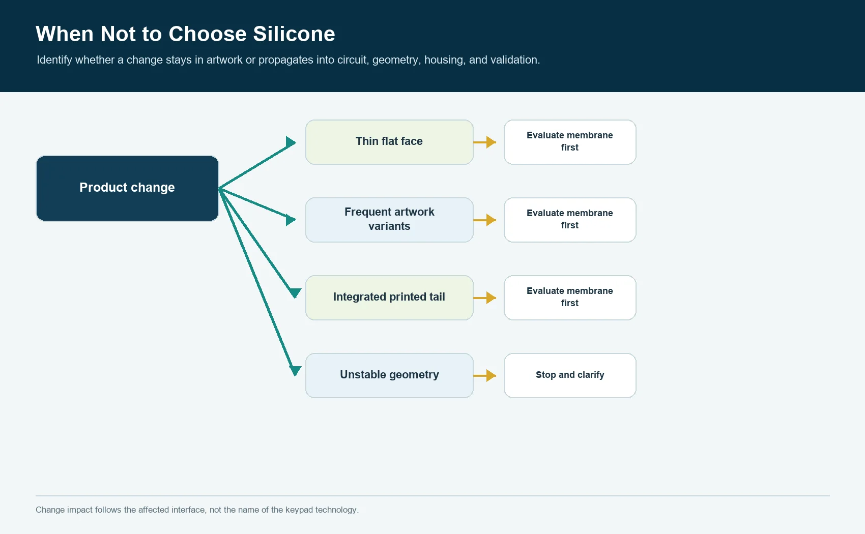
Main disqualifier for silicone: if the product must stay very thin and flat,
uses frequently changing printed graphics, or benefits from one bonded overlay
that carries graphics and circuitry, a membrane keypad may be the cleaner
architecture.
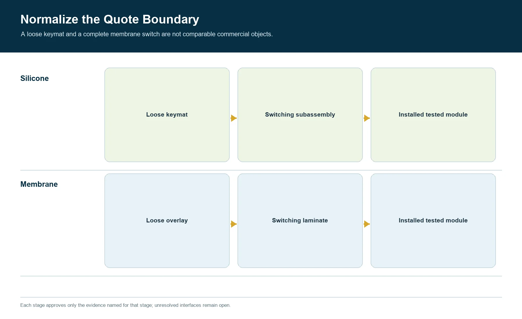
Keep the Comparison Boundary Identical
The comparison fails when the silicone option is priced as a loose molded
keymat while the membrane option is priced as a decorated, bonded, terminated,
and electrically tested assembly. It also fails in the opposite direction:
silicone may be quoted with a PCB, LEDs, connector, and support while the
membrane quote excludes the mounting panel or controller interface.
Normalize these boundaries before discussing preference:
| Boundary question | Silicone option must state | Membrane option must state |
|---|---|---|
| User surface | molded key tops, texture, color, legends, coating if any | overlay material, texture, embossing, printed graphics, windows |
| Switching element | conductive contact, dome actuator, discrete switch actuator, or other defined interface | printed contact, metal dome, non-tactile contact, or other defined interface |
| Circuit | customer PCB/FPC/PET or supplier-provided circuit | printed circuit layers, tail, connector, shielding if included |
| Structural reaction | PCB support, carrier, housing ribs, hard stops | panel support, spacer stack, dome support, mounting substrate |
| Lighting | LED board, light guide, light blocking, legend construction | LEDs, light guide, electroluminescent or other source, windows and masks |
| Mounting | captured perimeter, fasteners, adhesive, carrier, gasket interface | rear adhesive, mechanical frame, gasket, panel cutout |
| Validation | loose-part checks versus installed-system checks | laminate checks versus installed-system checks |
| Service item | keymat, circuit, module, or full control panel | overlay, bonded switch, tail, module, or full control panel |
The selected architecture should not inherit a hidden obligation that appears
only after design release.
Define the Two Architectures Without Marketing Shortcuts
A silicone keypad is a molded elastomer interface. Its raised keys, walls,
webs, perimeter, contacts, light-control features, and locating details may be
formed in one molded part, but the electrical circuit and reaction structure
still have to be defined. WACKER documents that silicone processing can use
different molding routes and that material and process selection are linked.[1]
That is a material-manufacturer relationship, not evidence that JASPER uses a
particular route for every project.
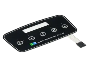
A membrane keypad is a laminated interface built from selected graphic,
spacer, circuit, adhesive, dome, tail, shielding, and mounting layers. Not every
design contains every layer. Mylar Specialty Films identifies a polyester film
that can accept graphic, conductive, and dielectric inks for membrane-touch
switch graphic and circuit layers.[2] Henkel separately identifies a
screen-printable conductive ink intended for low-voltage circuitry on
polyester film.[3] Those sources establish possible building blocks, not a
universal JASPER stack.
The useful distinction is structural: silicone obtains much of its shape and
spring behavior from a molded elastomer geometry; a membrane keypad obtains
its interface behavior from a converted and laminated layer system, sometimes
with a separate tactile dome.
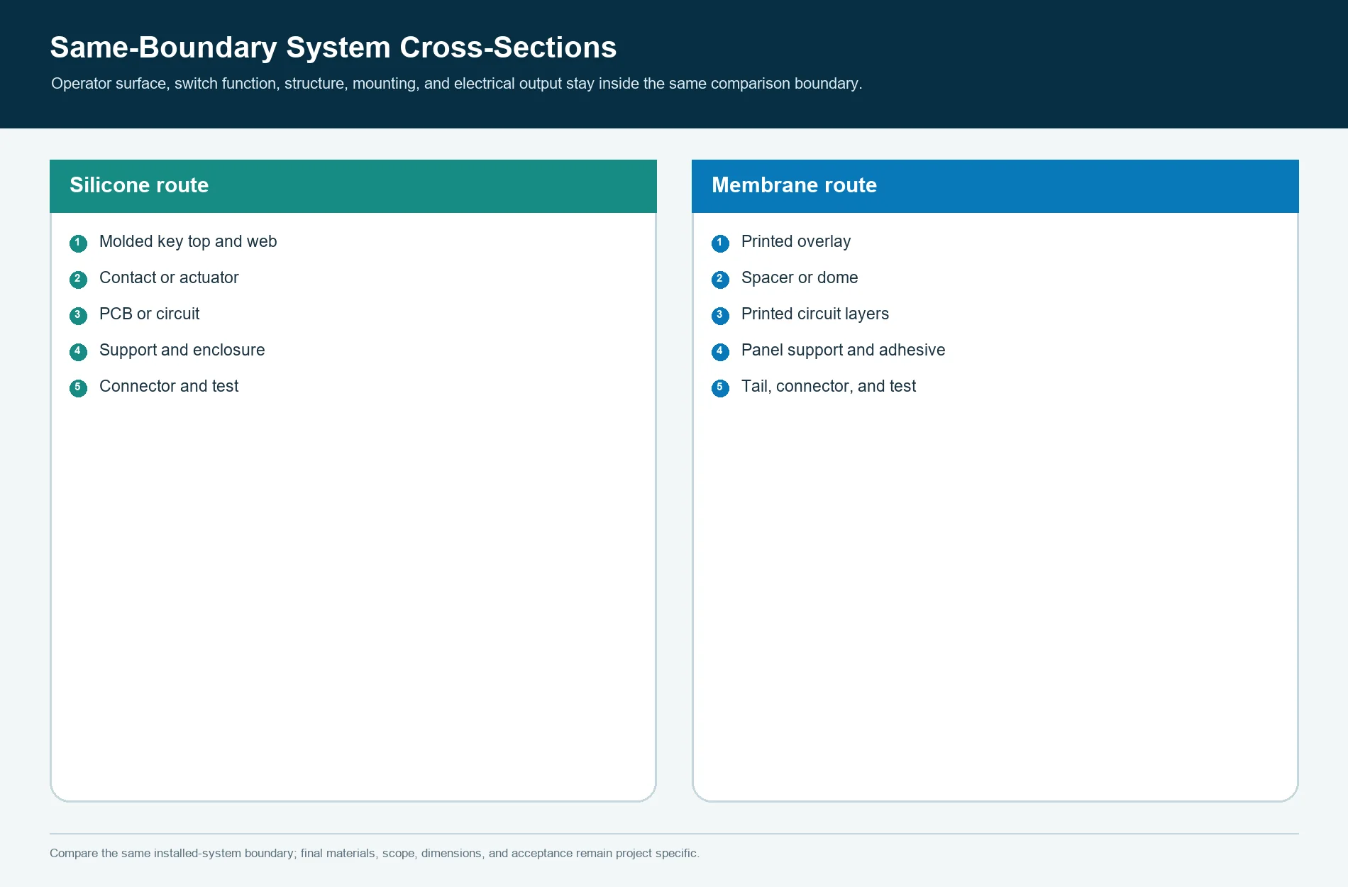
Compare the System Cross-Sections
The following sections use the same external functions: finger input, visible
legend, electrical closure, support, enclosure mounting, and connector output.
SILICONE SYSTEM

operator
   |
molded key top + legend/finish
   |
molded wall/web/guide
   |
conductive contact or actuator
   |
PCB, FPC, PET circuit, dome, or discrete switch
   |
support plate / housing reaction
   |
enclosure capture + perimeter path + connector


MEMBRANE SYSTEM

operator
   |
printed graphic overlay + optional emboss
   |
overlay adhesive / spacer / optional tactile dome
   |
printed circuit contact layers
   |
rear adhesive or mechanical support
   |
mounting panel / enclosure + flexible tail + connector
The drawings expose the sourcing question. Silicone does not eliminate the
circuit. A membrane keypad does not eliminate structural support. Whichever
quote omits these items transfers their engineering, tolerance, purchasing, and
failure ownership elsewhere.
Freeze the Common Input Sheet Before Comparing Samples
Give both candidate architectures the same requirements package:
- operator, glove, key roles, viewing direction, and accessibility needs;
- product envelope, front-surface geometry, panel cutout, and internal keepouts;
- circuit logic, key map, connector, tail route, grounding, and shielding needs;
- graphics, languages, icons, color references, windows, indicators, and
backlighting states; - dust, liquid, cleaning, oil, UV, temperature, storage, vibration, and impact
exposures that actually apply; - enclosure seal path, fasteners, mounting substrate, drainage, vents, cable
exits, and service openings; - validation methods, sample states, acceptance criteria, traceability, and
change-notification needs; - prototype phases, launch forecast, annual demand scenario, product life, and
service strategy; - supplied boundary, customer-furnished parts, inspection records, packaging,
and final test responsibility.
Unknown inputs should be marked unknown rather than replaced with supplier
defaults. The architecture decision can remain open while the team resolves the
few unknowns that could reverse it.
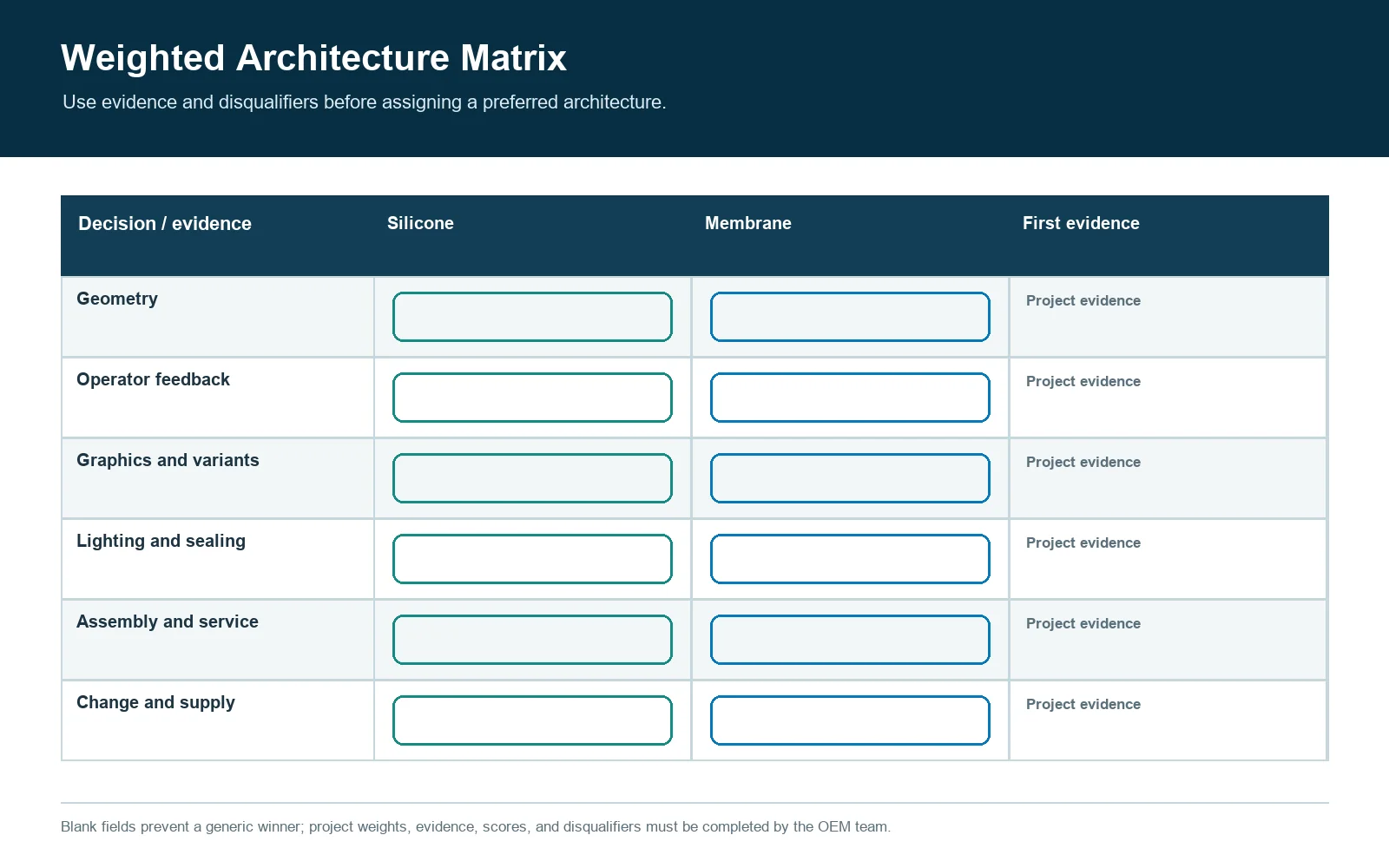
Use a Weighted Architecture Matrix
Do not treat every row as equally important. Assign project weights before
anyone sees the candidate scores. A safety-related glove control may weight
finger location heavily. A compact handheld may weight package depth and
graphic variation more heavily.
| Decision criterion | Silicone tends to fit when | Membrane tends to fit when | Evidence needed before selection |
|---|---|---|---|
| Front geometry | raised, sculpted, separated, guarded, or angled keys are important | a flat or lightly embossed surface is preferred | representative key field and enclosure section |
| Operator feedback | molded geometry and elastomer response are central to the interaction | dome or non-tactile laminate response is acceptable | installed sample with intended support |
| Package envelope | enclosure can accept molded key height and the circuit below | interface must minimize front-stack depth | full tolerance stack, not catalogue thickness |
| Graphics | legends are stable and can use molded color, printing, coating, or laser opening | artwork, branding, language, or model variants may change more often | variant map and artwork-change forecast |
| Circuit integration | a separate PCB or switch board already serves other functions | printed circuitry and tail should be integrated with the front interface | circuit ownership and connector drawing |
| Backlighting | molded light paths and raised illuminated keys support the industrial design | flat icons, windows, or a laminated light system suit the panel | powered stack in the actual housing |
| Sealing contribution | molded perimeter or captured rubber geometry supports the enclosure concept | bonded overlay and controlled panel interface support the seal concept | complete enclosure leak path and test state |
| Service strategy | keymat or module can be mechanically captured and separately replaced | bonded switch replacement as an assembly is acceptable | service work instruction and spare-part boundary |
| Change frequency | geometry and key map are expected to stabilize before tool commitment | late graphic or circuit revisions are plausible | revision forecast and change-cost model |
| Supply chain | OEM can control keypad, circuit, housing, and assembly interfaces | one converted laminate can consolidate graphics, circuit, tail, and mounting | responsibility matrix and incoming test plan |
The matrix is a discussion tool, not a universal scorecard. If a single
must-have requirement disqualifies one route, do not average that failure away.
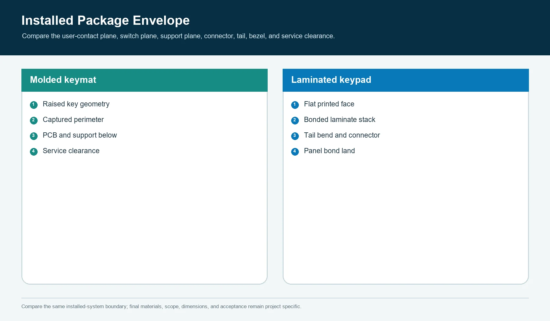
Packaging Depth Is a Stack Decision
A membrane keypad is often selected when the front interface must remain thin
and planar. That advantage can disappear if the design later adds a thick
carrier, separate light guide, tall components, a deep bezel, or a protective
cover. Conversely, a silicone keypad may occupy more visible depth but can use
that volume to provide finger location, key separation, guards, or a shaped
surface.
Compare these installed dimensions:
- enclosure front surface to operator contact surface;
- operator surface to electrical switch plane;
- switch plane to structural reaction surface;
- space for LEDs, components, connectors, and tail bend;
- permitted movement before electrical closure and structural stop;
- tolerance consumed by adhesive, carrier, PCB, housing, gasket, and fasteners;
- service clearance and disassembly path.
No universal thickness or travel threshold belongs in this decision. The
release drawing should state the permitted envelope and the production-intent
stack that satisfies it.
Key Feel Starts with the Operator Task
Silicone can provide raised shapes and an elastomer force response. A membrane
keypad can use tactile domes, embossed features, non-tactile switching, or a
combination. Neither architecture is automatically more tactile in every
assembly.
Evaluate the operator’s real action:
- center press versus edge press;
- bare finger versus the declared glove;
- deliberate command versus repeated data entry;
- visual confirmation versus eyes-off operation;
- audible feedback allowed or undesirable;
- adjacent-key isolation;
- return after contamination or environmental conditioning;
- response after installation torque and enclosure compression.
SK-05 does not set force, travel, snap, return, or web-geometry values. Those
values belong to the project specification and, for silicone geometry, to the
dedicated force and travel study. Here the decision is architectural: does the
user need a molded key field, or can the required interaction be delivered by a
laminated switch construction?
Graphics and Variant Management Can Reverse the Choice
A membrane keypad can place printed graphics over the switching layers, so
branding, language, icon, color, and window variants may be managed through
artwork and converted layers when the circuit and mechanics remain unchanged.
The change is not automatically trivial: print screens, color approval,
registration, die-cut files, inventory, validation, and part numbering may
still change.
Silicone graphics may use molded color, printing, applied coating, laser-opened
legends, molded icons, inserts, or separate caps. Some variants can be handled
by secondary decoration; others affect the mold or the optical stack. A
geometry change is not an artwork change.
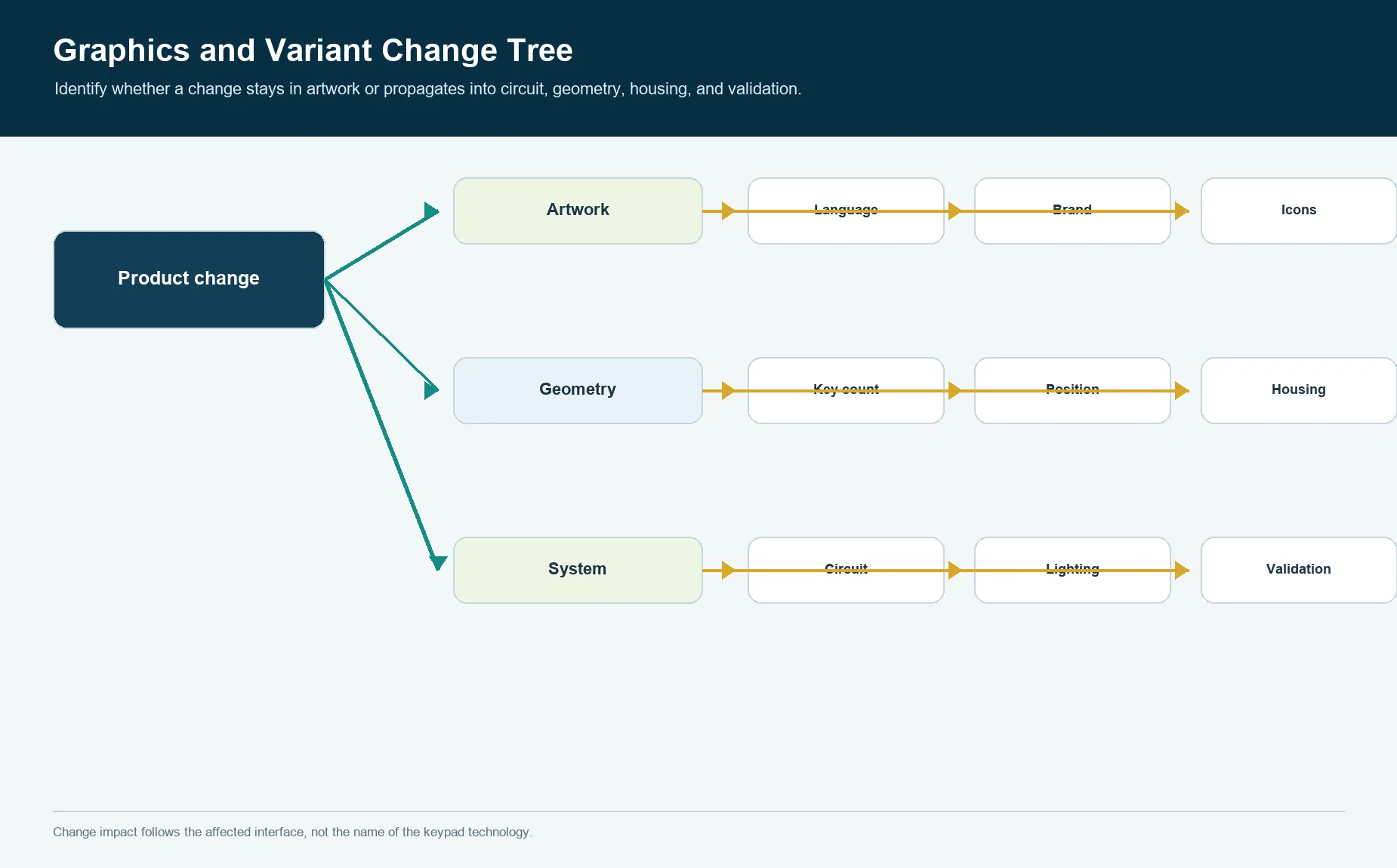
Before selection, create a variant tree:
| Change forecast | Questions for both routes |
|---|---|
| Language or brand | Can the base mechanical and electrical design remain common? |
| Icon position | Does artwork move only, or does the switch/key center move? |
| Key count | Does the circuit, tool, spacer, housing, connector, or firmware map change? |
| Day/night appearance | Which masks, inks, coatings, light paths, and powered checks change? |
| Model differentiation | Can late configuration occur without creating mixed inventory? |
If model variation is mostly printed information, membrane deserves serious
consideration. If variation requires distinct raised geometry or strong
eyes-off differentiation, silicone may justify the earlier geometry commitment.
Backlighting Must Be Compared as an Optical Chain
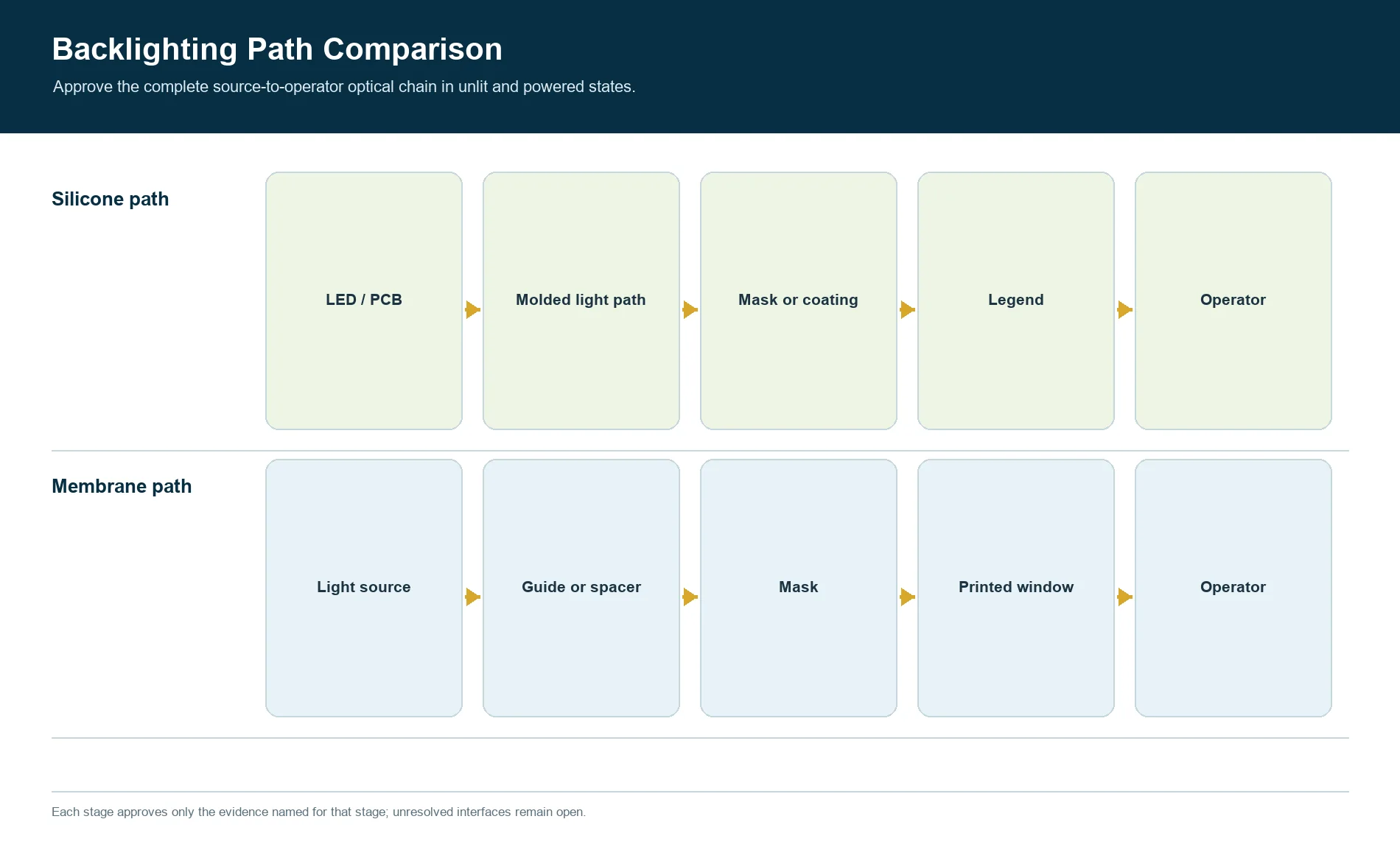
Both architectures can support illuminated legends and indicators, but their
light paths differ. The silicone route may use translucent molded regions,
coated and opened legends, light-blocking geometry, LEDs, and a PCB. The
membrane route may use transparent or printed windows, masks, light guides,
spacer features, LEDs, or another specified source.
Compare the same powered conditions:
source and drive -> position -> air gap or guide -> structural layers -> mask and legend -> operator
Review unlit appearance, powered readability, hot spots, leakage, cross-talk,
color, viewing angle, assembly variation, and service replacement. Do not award
the backlighting row from an unpowered sample. Do not infer a JASPER light
source, process, measurement method, or result until the quotation confirms the
actual project boundary.
Sealing Belongs to the Complete Enclosure
Silicone may contribute a molded perimeter lip, compression feature, or
continuous elastomer surface. A membrane keypad may contribute a bonded overlay
and adhesive interface over a controlled panel. Neither loose component owns an
ingress rating.
IEC 60529 classifies protection provided by an enclosure.[6] The evaluated
configuration must therefore include the keypad, panel or bezel, housing joints,
fasteners, connector or tail exit, vents, drainage, service openings, and
assembly condition.
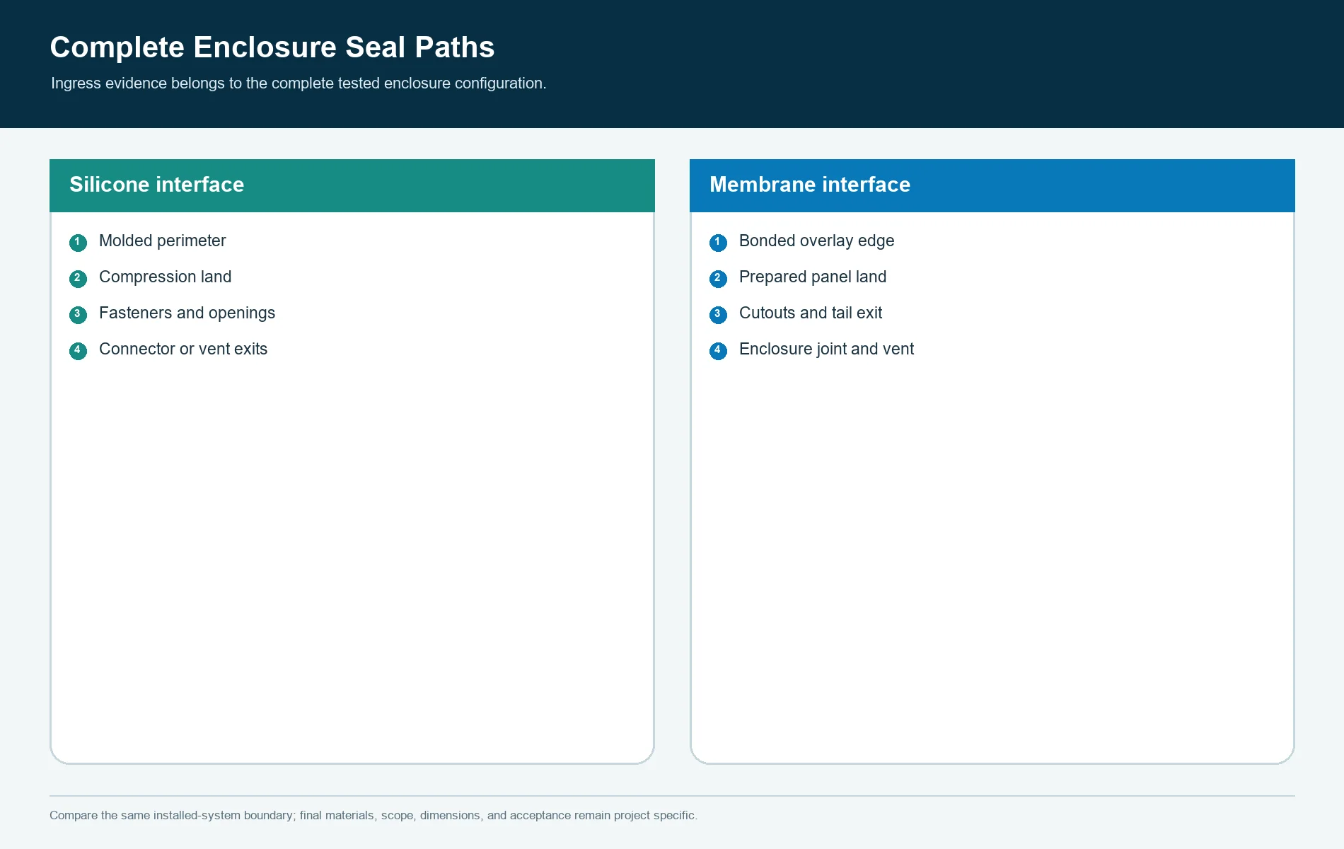
Use a leak-path review:
outside
  -> key field or overlay edge
  -> perimeter bond or compression land
  -> panel cutout and fasteners
  -> tail / cable / connector exit
  -> enclosure joint, vent, or service opening
  -> protected electronics volume
Silicone should not win simply because rubber is associated with sealing.
Membrane should not win simply because the front appears continuous. Compare
the actual path and the planned test article.
Tooling and Non-Recurring Cost Have Different Shapes
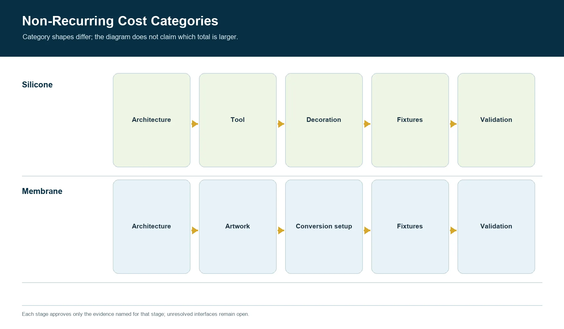
Silicone commonly requires a mold and may require separate fixtures, decoration
setup, contact integration, and production-intent sample correction. Membrane
keypads can require artwork preparation, print screens, cutting tools or
programs, lamination fixtures, dome or spacer setup, electrical tooling, and
inspection fixtures. Both routes can create non-recurring engineering work.
The correct question is not which technology has no tooling. Ask:
- which costs are paid before representative samples exist;
- which costs are reused across graphics or model variants;
- which costs repeat after a key-map, circuit, housing, or material change;
- which tools are customer-owned, supplier-owned, or project-dedicated;
- which fixtures control production and which only support development;
- what evidence closes each approval stage;
- what happens to tooling and data after a supplier change or product transfer.
Detailed silicone tool approval belongs to SK-03, not this comparison. SK-05
uses tooling only as one boundary in the architecture and sourcing decision.
Assembly Can Consolidate Risk or Hide It
A membrane keypad may arrive as one laminate carrying the graphic face, switch
circuit, flexible tail, rear adhesive, and optional tactile elements. That can
reduce line-side part count, but the OEM still owns panel preparation,
alignment, bond application, tail routing, connector mating, support, and final
function unless the quote says otherwise.
A silicone keypad may arrive as a loose keymat for installation over a
customer PCB, or as a broader assembly with circuit, LEDs, connector, support,
and functional checks. The membrane keypad manufacturing route
and JASPER’s product pages describe commercial starting points, but they do not
prove the exact assembly scope for this project.
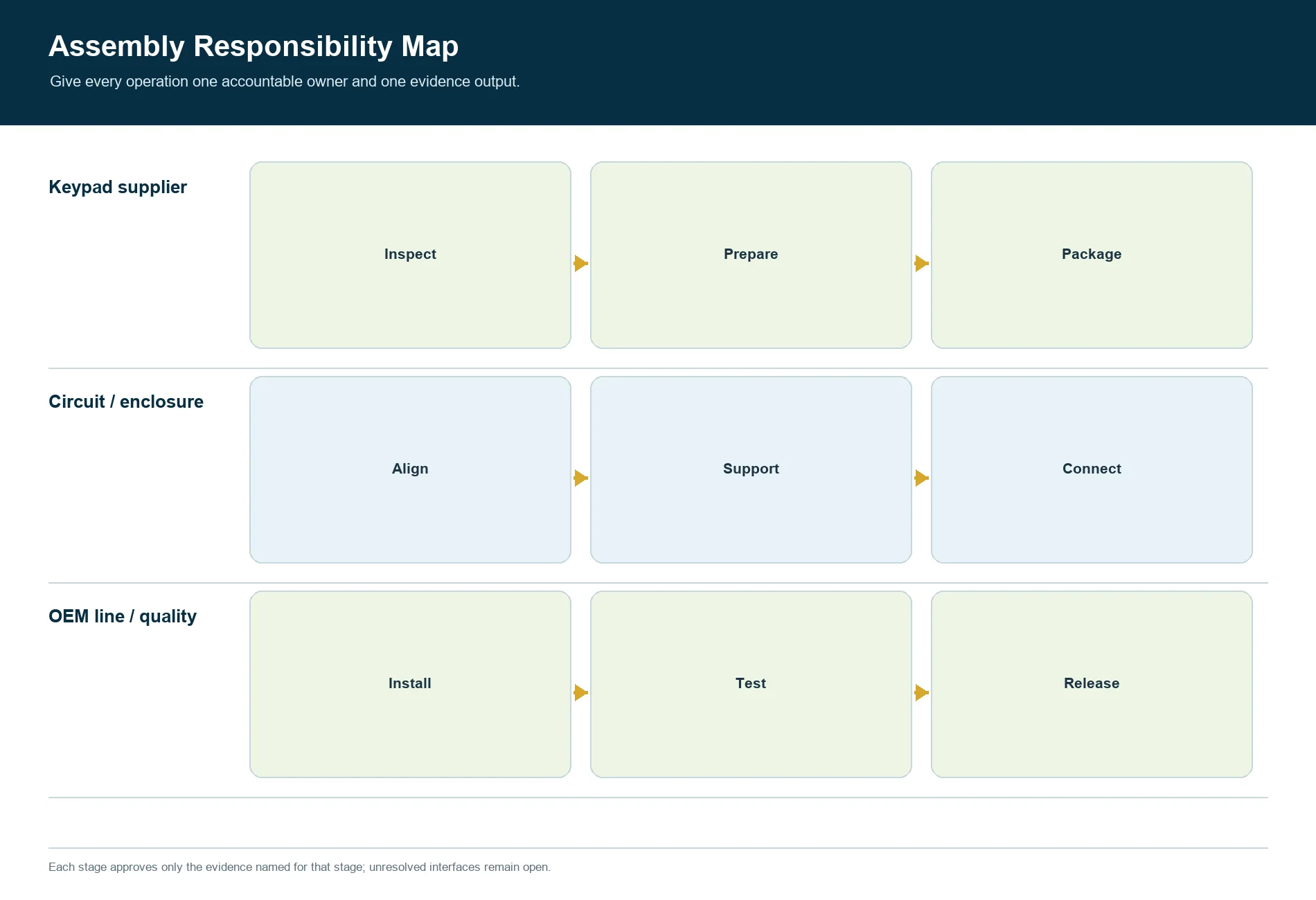
Create a responsibility table with one owner for every operation:
- incoming inspection;
- surface cleaning and preparation;
- datum-based location;
- adhesive lamination or mechanical capture;
- PCB, dome, spacer, or switch placement;
- LED and optical assembly;
- tail routing and strain control;
- fastener sequence and compression;
- electrical test;
- visual and powered inspection;
- enclosure verification;
- packaging and traceability.
If an operation has two assumed owners, it has no reliable owner.
Service and Repair Should Be Designed Before Adhesive Release
Serviceability depends more on attachment and module partitioning than on the
technology name.
A mechanically captured silicone keymat may be removable from the PCB and
housing, but that advantage disappears if it is bonded, overmolded, or trapped
behind a destructive enclosure joint. A membrane keypad may be replaceable as
a complete bonded switch, yet removal can damage the mounting surface or
require controlled cleaning and relamination.
Define:
- field-replaceable unit;
- permitted disassembly tools and access;
- whether seals or adhesives are single-use;
- cleaning and surface-preparation method;
- connector access and tail bend risk;
- calibration or functional test after replacement;
- spare-part shelf, artwork, and revision control;
- disposition of mixed old and new front panels.
For products with no field service, manufacturing rework still needs a boundary.
Scrap exposure can differ sharply between a replaceable keymat, a bonded
laminate, and a fully assembled HMI module.
Engineering Changes Do Not Affect the Architectures Equally
Classify expected changes before the design is frozen:
| Change type | Silicone exposure | Membrane exposure |
|---|---|---|
| Legend text or language | decoration, artwork, inspection, inventory; mold only if the legend is molded | overlay artwork, print setup, inspection, inventory |
| Key position or shape | mold, housing clearance, circuit alignment, feel, lighting | overlay, spacer, circuit, dome, panel and tail layout |
| Circuit map | PCB/contact interface and possibly key geometry | printed circuit, spacer, tail, connector and test fixture |
| Enclosure stack | preload, support, key clearance, seal path | bond land, support, panel opening, tail route, seal path |
| Light source | molded optical path, masks, legends, PCB and housing | windows, masks, guide, circuit and housing |
| Supplier material | force, dimensions, appearance, adhesion, optics, environment | print, resistance, adhesion, dimensions, graphics, environment |
The table does not predict cost. It identifies which controlled interfaces must
be reviewed and requalified. A “small” change is small only when its affected
interfaces are known.
Set the Total Cost Boundary
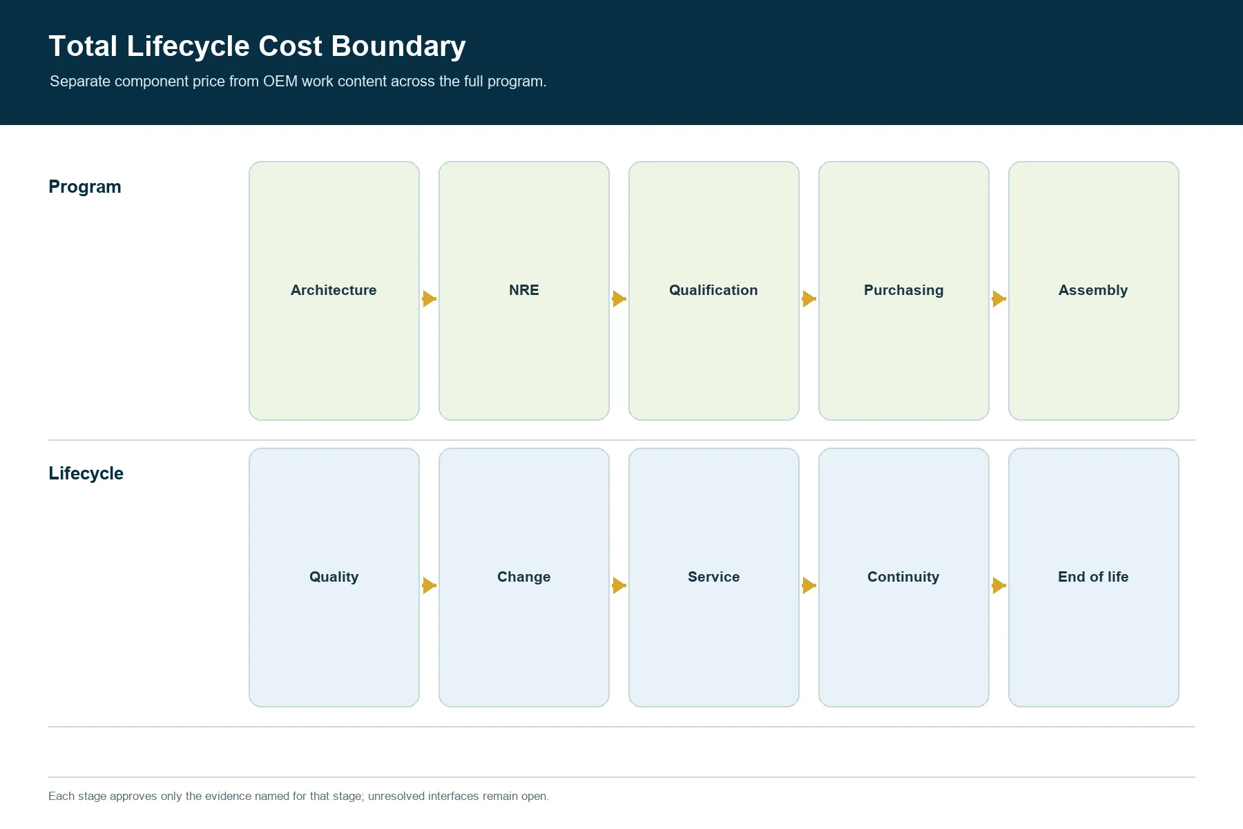
Compare total cost by life stage, with project-specific quotations and internal
labor rather than generic industry averages.
| Life stage | Include for silicone | Include for membrane |
|---|---|---|
| Architecture | keymat, circuit, support, housing, lighting and seal engineering | overlay, spacer, circuit, support, lighting, bond and tail engineering |
| Non-recurring | mold and revision work, fixtures, decoration setup, sample builds | artwork, screens, cutting/lamination setup, fixtures, sample builds |
| Qualification | loose and installed mechanical/electrical/visual/environment evidence | laminate and installed mechanical/electrical/visual/environment evidence |
| Purchasing | part or module price, mating board, support, decoration, packaging | laminate or module price, support panel, connector, packaging |
| Assembly | alignment, capture or bonding, PCB and lighting, fasteners, test | surface preparation, lamination, tail routing, connector, test |
| Quality | incoming checks, curve/function/visual checks as specified, traceability | incoming checks, circuit/function/visual/bond checks as specified, traceability |
| Change | tool or decoration revisions, obsolete keymats and mating parts | artwork/circuit/tooling revisions, obsolete overlays and laminates |
| Service | replacement unit, disassembly, resealing, test, spare inventory | removal, surface recovery, relamination, test, spare inventory |
| Supply continuity | tool transfer, material approval, alternate process and records | artwork/data transfer, material approval, alternate converter and records |
| End of life | final buy, tool/data retention, spare compatibility | final buy, artwork/data retention, spare compatibility |
This model prevents a sourcing team from comparing two unit prices while
ignoring different OEM work content. It also reveals when a more expensive
component removes a larger assembly or service burden.
Quantity Matters Through Cost Allocation and Change Risk
Quantity affects how non-recurring work is allocated, how much automation is
worth considering, how many variants remain economical, how much inventory
becomes exposed to revision, and how strongly production repeatability matters.
There is no universal quantity threshold at which one architecture wins.
Use scenarios instead:
- development and engineering builds;
- launch demand;
- expected steady demand;
- upside and downside demand;
- variant mix;
- service-spare demand;
- redesign or regulation-change probability;
- supplier-transfer probability;
- product-life and final-buy strategy.
Then compare total cost and cash timing for each scenario. A stable, long-lived
geometry may absorb dedicated silicone tooling differently from a product with
frequent front-panel variants. A membrane design with low initial commitment
can still accumulate repeated artwork, setup, validation, and obsolete
inventory costs when variants multiply.
Select by Application Behavior, Not Industry Label
The industrial control application is a
relevant context because operator gloves, contamination, cleaning, visibility,
enclosure structure, and service access can influence the interface. The page
does not prove that every industrial product should use either keypad type.
Silicone often deserves evaluation for:
- raised controls located by touch;
- differentiated key shapes or guards;
- products whose industrial design uses a molded key field;
- assemblies where a captured elastomer part supports the enclosure concept;
- interfaces where a separate PCB already carries switches, LEDs, and logic.
Membrane often deserves evaluation for:
- thin planar control surfaces;
- dense printed legends or multiple front-panel variants;
- integrated printed circuitry and a flexible tail;
- bonded interfaces with a continuous wipeable face;
- products where low-profile embossing or domes provide sufficient feedback.
Hybrid systems are also valid. A silicone actuator can operate a separate
switch. A membrane assembly can sit behind a bezel or molded key feature. The
best answer may be a mixed architecture if its additional interfaces are
explicitly controlled.
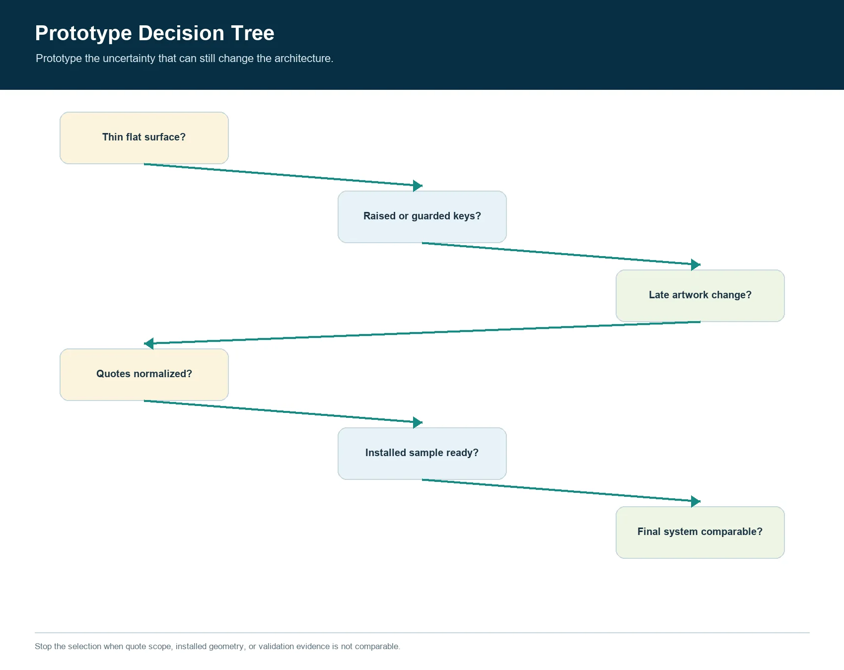
Follow the Prototype Decision Tree
START
  |
  +-- Is a thin, flat, printed front surface a must-have?
  |       |
  |       +-- YES -> prototype membrane stack first
  |       |
  |       +-- NO
  |
  +-- Are raised shape, eyes-off location, guards, or molded geometry essential?
  |       |
  |       +-- YES -> prototype silicone stack first
  |       |
  |       +-- NO
  |
  +-- Will graphics or language change after mechanical freeze?
  |       |
  |       +-- OFTEN -> keep membrane and shared-artwork options open
  |       |
  |       +-- RARELY
  |
  +-- Does either quote omit circuit, support, lighting, mounting, or test?
  |       |
  |       +-- YES -> normalize the supply boundary before scoring
  |       |
  |       +-- NO
  |
  +-- Build two risk-focused installed prototypes
          |
          +-- compare operator task, package, optics, seal path,
              assembly, validation, change, service, and total cost
The decision tree tells the team which prototype to build first. It does not
replace the final installed comparison.
JASPER’s prototyping capability page frames
prototype work around fit, function, appearance, feel, lighting, and assembly.
The exact silicone tool, membrane conversion, test equipment, sample stages,
and deliverables for SK-05 still require quotation confirmation.
Build Prototypes That Answer Different Questions
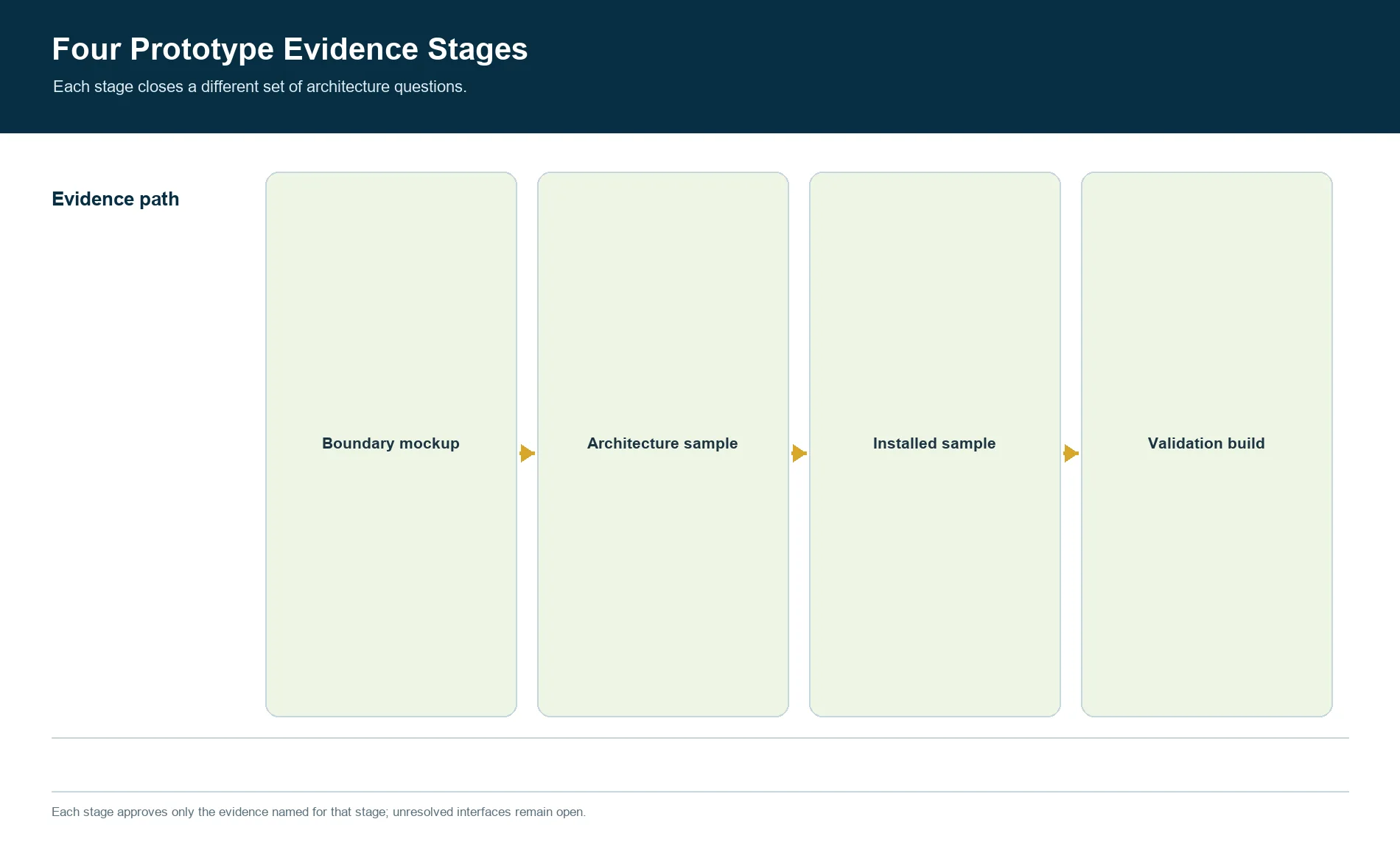
Use staged evidence rather than asking one sample to approve everything.
Boundary mockup
Confirm the front envelope, key field, operator reach, panel opening, PCB or
tail route, connector access, support, lighting volume, and service access.
This stage may use non-production materials and therefore cannot approve final
feel, bond, circuit, decoration, environment, or life.
Architecture sample
For silicone, use representative molded geometry and the intended circuit or
switch interface. For membrane, use representative overlay, spacer, circuit,
dome if applicable, tail, and support. Compare the same operator tasks in the
same enclosure concept.
Production-intent installed sample
Add the intended materials, decoration, lighting, connector, support, mounting,
fasteners, adhesive or compression, and enclosure. Record revision identity and
test configuration.
Validation build
Apply the project’s dimensional, functional, electrical, visual, environmental,
cleaning, cycling, sealing, packaging, and service checks. ASTM F1578-24
provides a membrane-switch contact-closure cycling framework, including
repeated depression and release to a predetermined cycle requirement.[5] It
does not set the product’s cycle count, load, specimen, electrical condition,
or pass criteria.
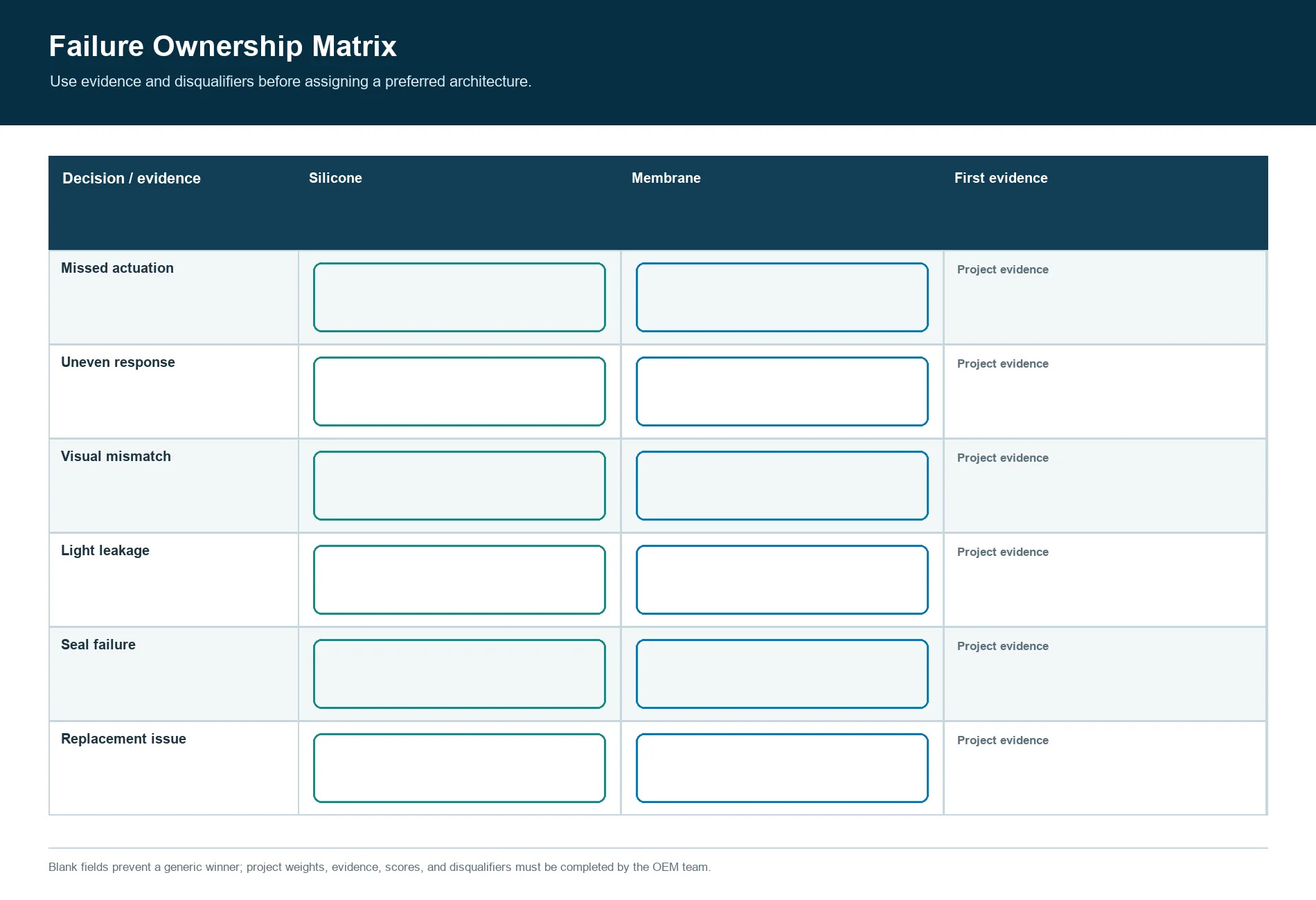
Compare Failure Ownership Before Supplier Selection
Ask which party diagnoses and corrects each system symptom:
| Symptom | Silicone investigation boundary | Membrane investigation boundary |
|---|---|---|
| missed actuation | key/contact alignment, circuit pad or switch, support, preload, contamination | spacer opening, dome/contact, printed circuit, support, contamination |
| uneven response | molded geometry, material/process, housing compression, support | dome or spacer variation, laminate support, panel flatness, bond |
| visual mismatch | molded color, decoration, legend, coating, light path | overlay print, registration, window, emboss, light path |
| light leakage | molded walls, masks, coating, LED position, housing | overlay masks, spacer/light guide, LED position, panel |
| seal failure | molded perimeter, compression land, fasteners, exits, housing | overlay bond edge, panel preparation, cutouts, exits, housing |
| assembly damage | keymat handling, PCB/contact alignment, compression | liner removal, adhesive contact, tail routing, lamination |
| field replacement issue | capture, connector, resealing, module access | adhesive removal, surface recovery, tail access, relamination |
Supplier selection should include access to evidence, revision records, and
corrective-action ownership rather than stopping at confirmation that a part
can be made.
Do Not Choose Silicone in These Conditions
Silicone is the wrong default when:
- the product requirement is a very thin, flat, continuously printed control
face and raised key geometry adds no operator value; - late language, branding, or model artwork changes are expected and the
mechanical key field can remain common; - the desired switch circuit and flexible tail should be integrated into the
same converted laminate; - a bonded, wipeable overlay is the preferred service and cleaning surface;
- molded depth conflicts with the enclosure, display, battery, PCB, or component
envelope; - the project cannot stabilize geometry before mold commitment;
- a proven membrane architecture already satisfies the operator, environment,
validation, supply, and service requirements; - the OEM cannot control the separate PCB, support, alignment, and assembly
interfaces that a loose keymat would create.
Choosing membrane in these cases is not a downgrade. It is a better match
between architecture and system boundary.
Stop the Decision When Evidence Is Not Comparable
Do not approve either route when:
- one sample is loose and the other is installed;
- the quotes include different circuit, connector, lighting, mounting, or test
content; - the enclosure support and seal path are undefined;
- graphic and language variants have not been counted;
- tooling ownership and revision charges are missing;
- prototype samples use different operator or environmental assumptions;
- lifecycle cost excludes OEM assembly, scrap, service, or change;
- a planned IP rating is attached to the loose keypad;
- the final PCB, panel, housing, or tail route is still moving;
- material, process, inspection, or change notification is assumed rather than
written.
An architecture decision made under unequal inputs is only a preference
recorded as if it were evidence.
OEM Input Package for a Comparable Quote
Send one controlled package to both architecture reviews.
Operator tasks and key roles
- application and product location;
- operator, glove, posture, viewing direction, and accessibility needs;
- key roles, frequency, accidental-actuation controls, and feedback preference;
- cleaning, contamination, liquid, dust, UV, temperature, storage, and
mechanical exposures.
Mechanical and enclosure
- 2D drawings and 3D models;
- front envelope, panel opening, PCB, support, housing, fasteners, and keepouts;
- key or switch centers, active areas, datum scheme, tolerances, and service
access; - mounting, bond land, capture, compression, drainage, vent, and seal path.
Electrical and optical
- key map, circuit, connector, tail route, grounding, shielding, and test
interface; - contact architecture and intended support;
- LED or other light source, drive, position, guide, mask, window, and powered
acceptance states.
Graphics and variants
- vector artwork, languages, icons, colors, textures, windows, embossing, and
legend method; - variant matrix, expected change timing, shared parts, and inventory strategy.
Commercial and validation
- prototype stages and quantities;
- launch, annual, variant, service, and end-of-life demand scenarios;
- required records, sample traceability, inspection, validation, packaging, and
change notification; - customer-furnished parts and the requested supply, assembly, and test
boundary.
Frequently Asked Questions
Is a silicone keypad always thicker than a membrane keypad?
The molded key field usually consumes a different package envelope from a flat
laminate, but the useful comparison is the complete installed stack. Include
support, PCB or printed circuit, lighting, carriers, adhesive, bezel, housing,
connector, and service clearance. Do not compare loose-part thicknesses.
Which keypad gives better tactile feedback?
Neither technology wins without a defined operator task and installed sample.
Silicone obtains response from molded elastomer geometry and its contact or
actuator interface. Membrane keypads can use tactile domes, embossing,
non-tactile switching, and panel support. Compare production-intent assemblies.
Is a membrane keypad cheaper because it has no mold?
That conclusion omits artwork, screens, cutting or converting setup,
lamination, fixtures, circuit tooling, prototype builds, inspection, validation,
and later revisions. Silicone and membrane architectures have different
non-recurring cost structures. Compare the full life-stage model with actual
quotes.
Which architecture is easier to seal?
Sealing depends on the complete enclosure. Silicone may provide a compressed
perimeter; membrane may provide a bonded overlay. Edges, panel openings,
fasteners, tail or connector exits, vents, joints, service openings, assembly,
and test configuration decide the result.
Which option is better for frequent graphic changes?
A membrane overlay often keeps printed information in a separable artwork layer,
which can help when language or branding changes but mechanics and circuitry do
not. Every revision still needs controlled files, setup, inspection,
validation, inventory, and part-number management.
Can a silicone keypad use a membrane circuit?
Yes, a molded silicone key can actuate a suitable PCB, FPC, PET circuit, dome,
or discrete switch architecture. The contact, support, alignment, travel,
electrical closure, and assembly boundary must be designed together.
Should prototype quantity determine the architecture?
No. Prototype strategy affects cash timing and available evidence, but the
production choice must also satisfy operator, package, graphics, circuit,
lighting, sealing, assembly, change, service, validation, quantity, and supply
requirements.
What is the minimum information for a useful comparison?
Provide the enclosure and circuit files, operator task, graphics and variants,
lighting, environment, mounting and seal path, connector, validation plan,
quantity scenarios, service strategy, and a common requested supply boundary.
Sources
- WACKER, Solid and Liquid Silicone Rubber – Material and Processing Guidelines
- Mylar Specialty Films, Melinex ST504 Technical Datasheet
- Henkel, LOCTITE EDAG 423SS E&C Conductive Ink
- 3M, Membrane Switch White Spacer 7966MWS Technical Data Sheet
- ASTM International, ASTM F1578-24 Contact Closure Cycling of a Membrane Switch
- IEC, IEC 60529 Degrees of Protection Provided by Enclosures
Material and standard sources support the architecture relationships and test
boundaries above. They do not establish a JASPER material, process, equipment,
test result, life, force, travel, thickness, volume, cost, lead time, or
enclosure rating. Project values require an approved drawing, quotation, sample
state, method, and acceptance plan.
Request a Keypad Architecture Review
Use the JASPER RFQ form to send the common input package,
both requested supply boundaries, quantity and variant scenarios, and the
decisions that remain open. Ask for the response to separate loose-part scope,
assembled scope, non-recurring items, prototype evidence, production
acceptance, change control, and exclusions for the silicone and membrane
options.
Ready to Start Your Project?
Tell us about your membrane switch, keypad, or graphic overlay requirements. Our engineering team will review your specifications and provide a detailed quote.