
OEM electronics · Board to interface
PCB Assembly for OEM Electronics
A clearer path from your board design to an integrated product.
Bring your PCB files, component list and interface requirements into one clearly scoped PCBA enquiry. Review the assembled board, the test requirements and how it connects to your keypad, display or enclosure.
Have Gerber files and a BOM? Start there. Still developing the board? Share your requirements for an initial scope review.
OEMs that ship with our switches inside





01 / Start with the right scope
What Is a Printed Circuit Board Assembly?
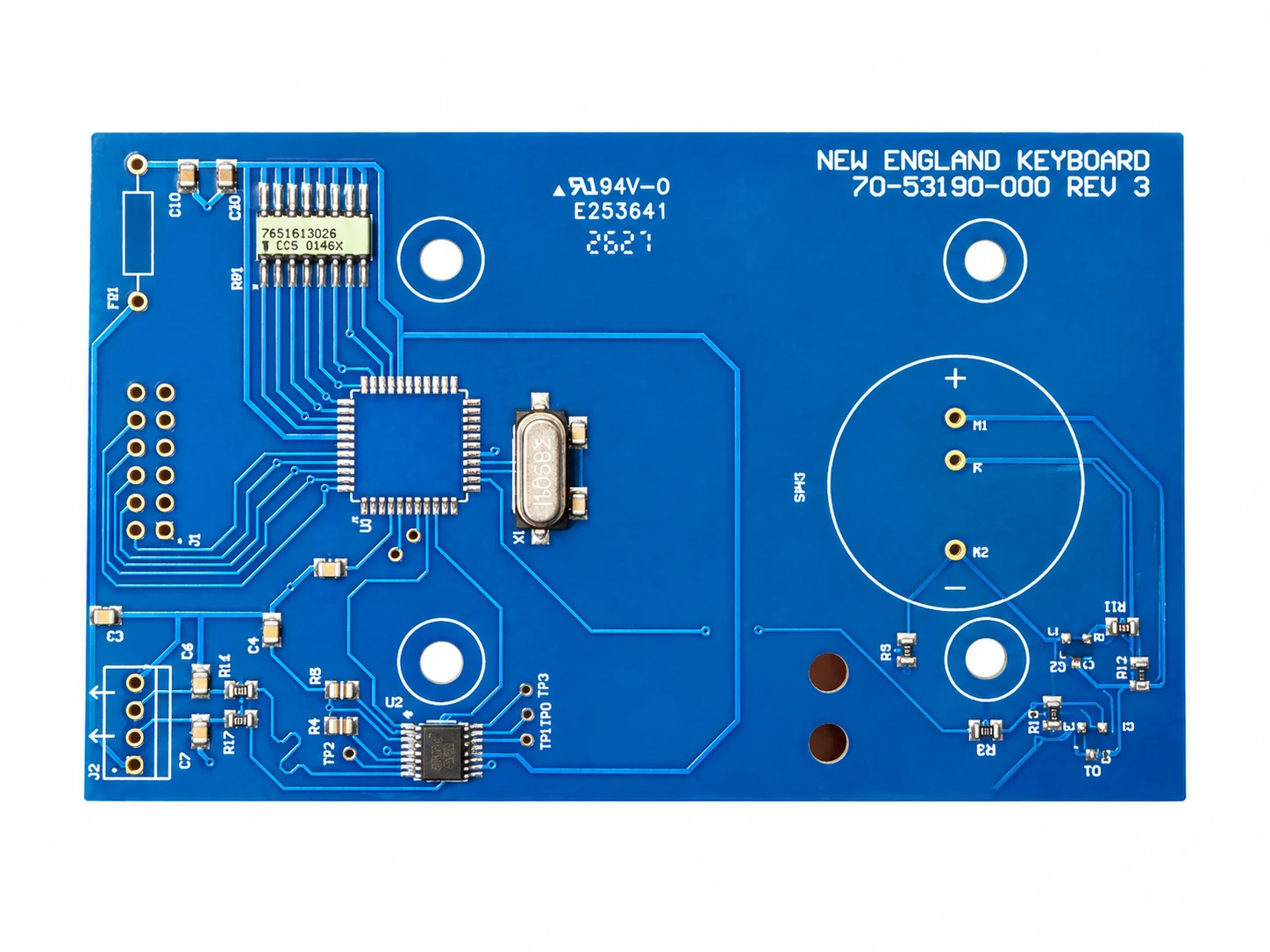
A printed circuit board assembly, or PCBA, is a circuit board with electronic components mounted and electrically connected to it. The bare PCB provides the interconnections; the assembled components perform the circuit’s functions.
A PCBA order needs more than a board outline. It also needs an agreed component list, assembly revision, inspection criteria and, where required, programming and electrical testing. For an OEM front panel, connector orientation, component height and the keypad or display interface matter just as much as the board itself.
| Scope | What it includes | What to clarify |
|---|---|---|
| Bare PCB | The fabricated board, copper connections, holes and specified finishes; no component assembly. | Board data, stack-up, material and fabrication requirements. |
| PCBA | The board plus fitted and soldered components, with the inspection and testing agreed for the build. | BOM, placement data, assembly notes, sourcing responsibility and acceptance plan. |
| Box build | A wider assembly that may add an enclosure, wiring, display, PCBA and other mechanical or electrical parts. | A separate integration scope, including who owns firmware and finished-system validation. |
A PCB or FPC membrane switch is a related interface construction, not automatically a complete control-board PCBA. If you need the finished operator-facing panel as well, review the HMI assembly route.
02 / Assembly requirements
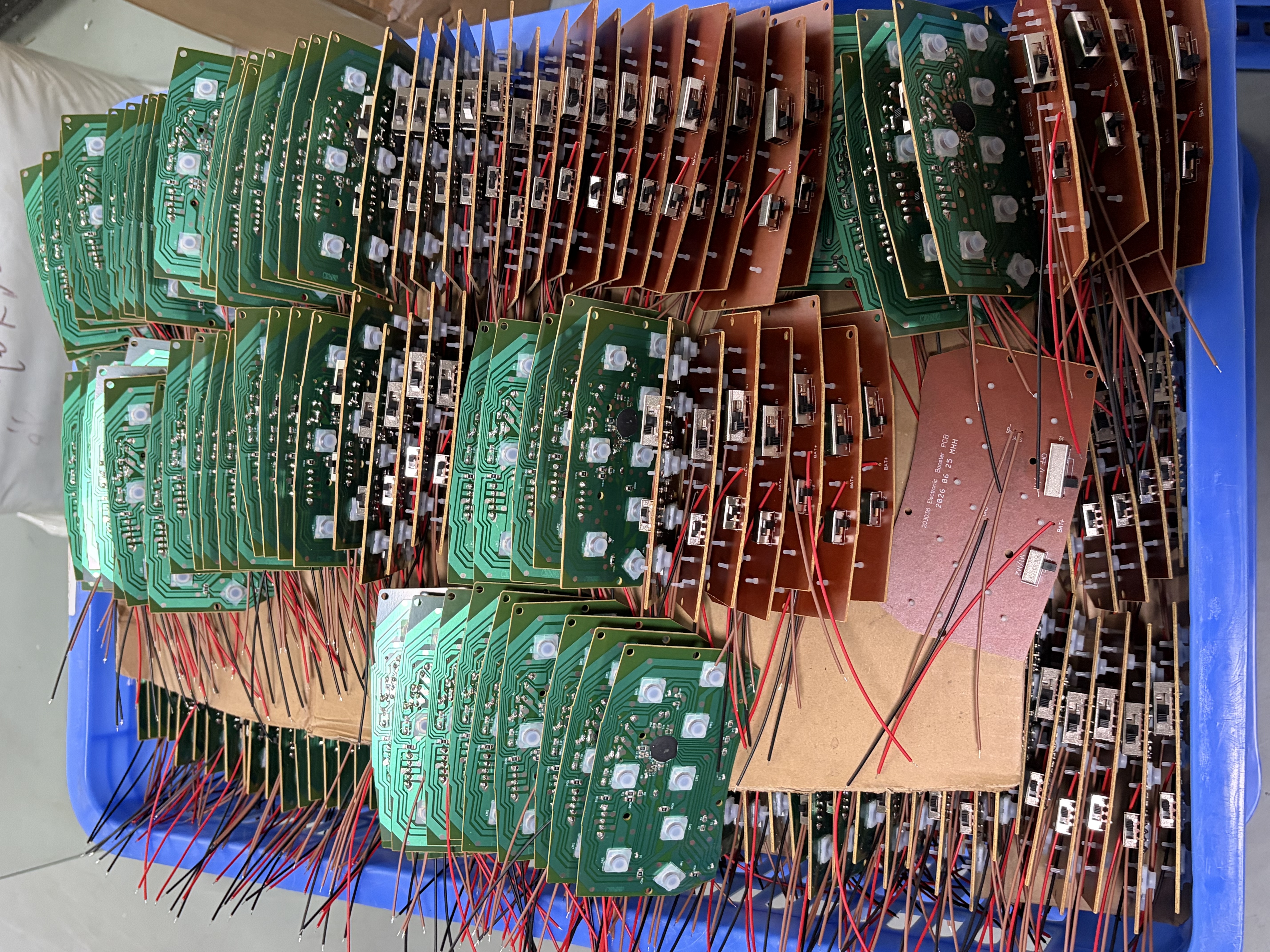
SMT, Through-Hole and Mixed-Technology PCB Assembly
The component package and board layout determine the assembly route. Specify the construction you need; the supported process, package range and inspection plan must be confirmed against the actual design before a build is accepted.
SMT assembly
Surface-mounted components attach to pads on the board. This route is widely used for compact electronic assemblies with a high component count.
Review: footprint matching, component polarity, solder-paste data, thermal limits and access to hidden joints.
THT assembly
Component leads pass through board holes and are soldered to the circuit. Connectors and some mechanically loaded parts may use this construction.
Review: hole and lead fit, insertion direction, solder-side access and the mechanical load carried by the joint.
Mixed assembly
A mixed-technology PCBA combines SMT and through-hole parts on one board, sometimes with assembly on both sides.
Review: operation sequence, heat exposure, underside clearance and components that need separate handling.
Beyond component placement
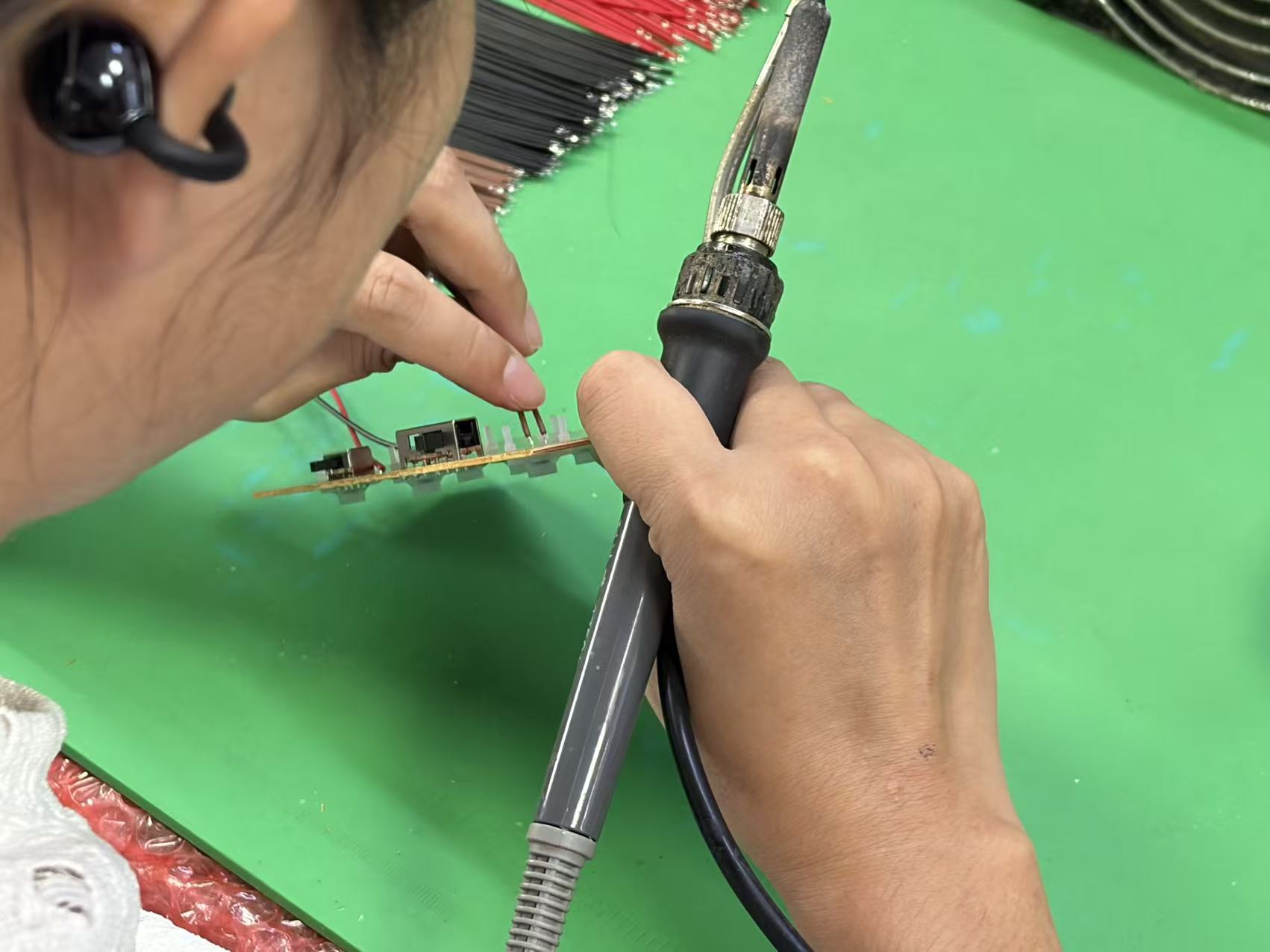
Plan the wire and connector operations
Wire leads and mechanically loaded components can require assembly operations beyond surface placement. Define wire length, polarity, solder-side access and strain relief in the assembly drawing.
Agree which operations follow reflow and how the completed connections will be inspected before the board is installed.
03 / Prevent avoidable rework
DFM and DFA: Review the Files Before Assembly
Design for manufacturing (DFM) and design for assembly (DFA) reviews check whether the release package can be built as intended. They do not replace the OEM’s circuit design verification. A good review identifies unresolved questions before materials are committed.
| Review area | Check together | Why it matters |
|---|---|---|
| File revision | Gerber or agreed board data, BOM, placement file and assembly drawing. | Prevents one revision of the board being assembled with another revision of the parts list. |
| Parts & orientation | Manufacturer part number, footprint, pin 1, polarity, do-not-fit positions and rotation. | Resolves mismatches that a component description alone cannot explain. |
| Physical access | Component spacing, board-edge clearance, mounting holes and connector mating direction. | Allows assembly, inspection, probing and installation without a mechanical clash. |
| Test access | Test points, power connections, programming header and required fixtures. | Avoids discovering after layout release that the agreed checks cannot reach the circuit. |
| Final interface | Enclosure datums, keypad contact positions, cable routing and display stack height. | A working board still has to fit and connect inside the finished product. |
For a front-panel project, include the custom membrane switch drawing at the same time as the board files. The two parts should share a controlled pinout and mechanical reference.
04 / Component ownership
BOM Control and Component Sourcing
A bill of materials should identify the manufacturer and exact part number for every fitted component, together with reference designators, quantities and any approved alternatives. A value such as “10 kΩ resistor” alone does not define the package, tolerance or other required characteristics.
Customer-supplied parts
Identify which boards and components you will supply. Agree delivery condition, quantities, spare material, handling requirements and how shortages or unused parts will be managed.
Turnkey sourcing request
If you want board and component sourcing included, mark it clearly in the RFQ. Availability, approved supply channels, responsibility and cost need confirmation against the BOM.
A shared supply model
You may wish to supply critical or proprietary parts and request sourcing for the remainder. Assign ownership line by line so the quotation does not omit or double-count material.
Do not leave substitutions implicit. State whether alternatives are prohibited, limited to a customer-approved list, or subject to approval before purchase. The review should consider electrical characteristics, package fit, temperature requirements, firmware implications and lifecycle status—not just nominal value.
These are sourcing models to discuss, not a promise that every requested part or procurement route is available. Record the accepted BOM revision and the change-approval process in the project scope.
05 / Understand the build
From Bare Board to Assembled Electronics
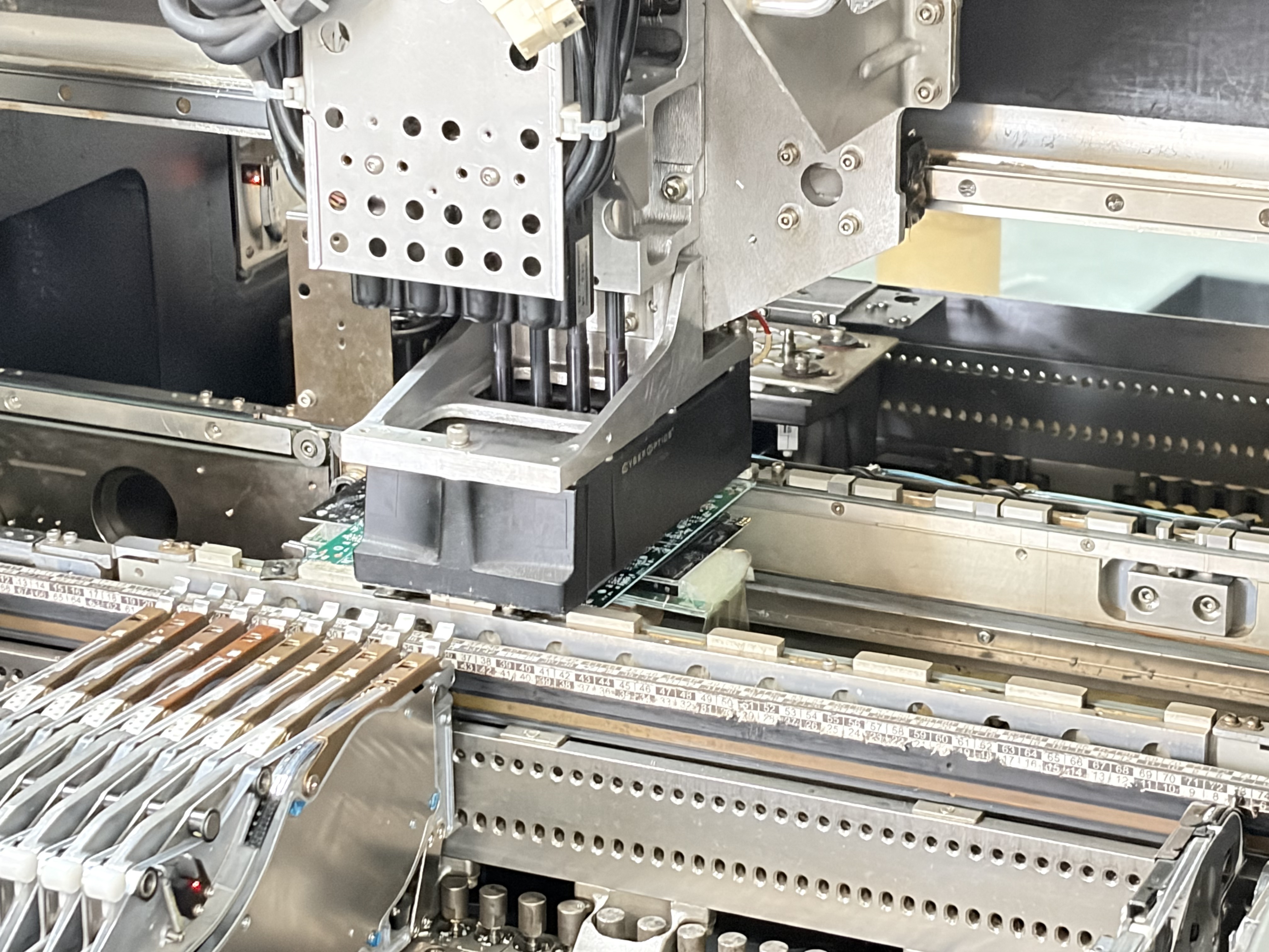
A typical PCB assembly sequence is shown below. The exact operations vary with the circuit, component packages and approved production route; this is a process explanation, not a list of equipment installed at JASPER.
- 01
Release the data and materials
Match the board data, BOM and placement instructions. Resolve missing parts, revision differences and special handling notes before the build.
- 02
Place and solder the components
For an SMT route, solder paste, component placement and reflow are typical stages. Through-hole components use the specified insertion and soldering method.
- 03
Inspect the assembly
Check relevant visible features and use additional inspection where the package or acceptance plan requires it. Hidden joints need a suitable inspection approach.
- 04
Program and test where specified
Apply the agreed firmware and electrical or functional checks only within the approved scope, using the required files, connections and pass/fail criteria.
- 05
Release for integration or delivery
Complete the specified records, identification and protective packaging. If a front panel is included, check the board-to-interface fit before acceptance.
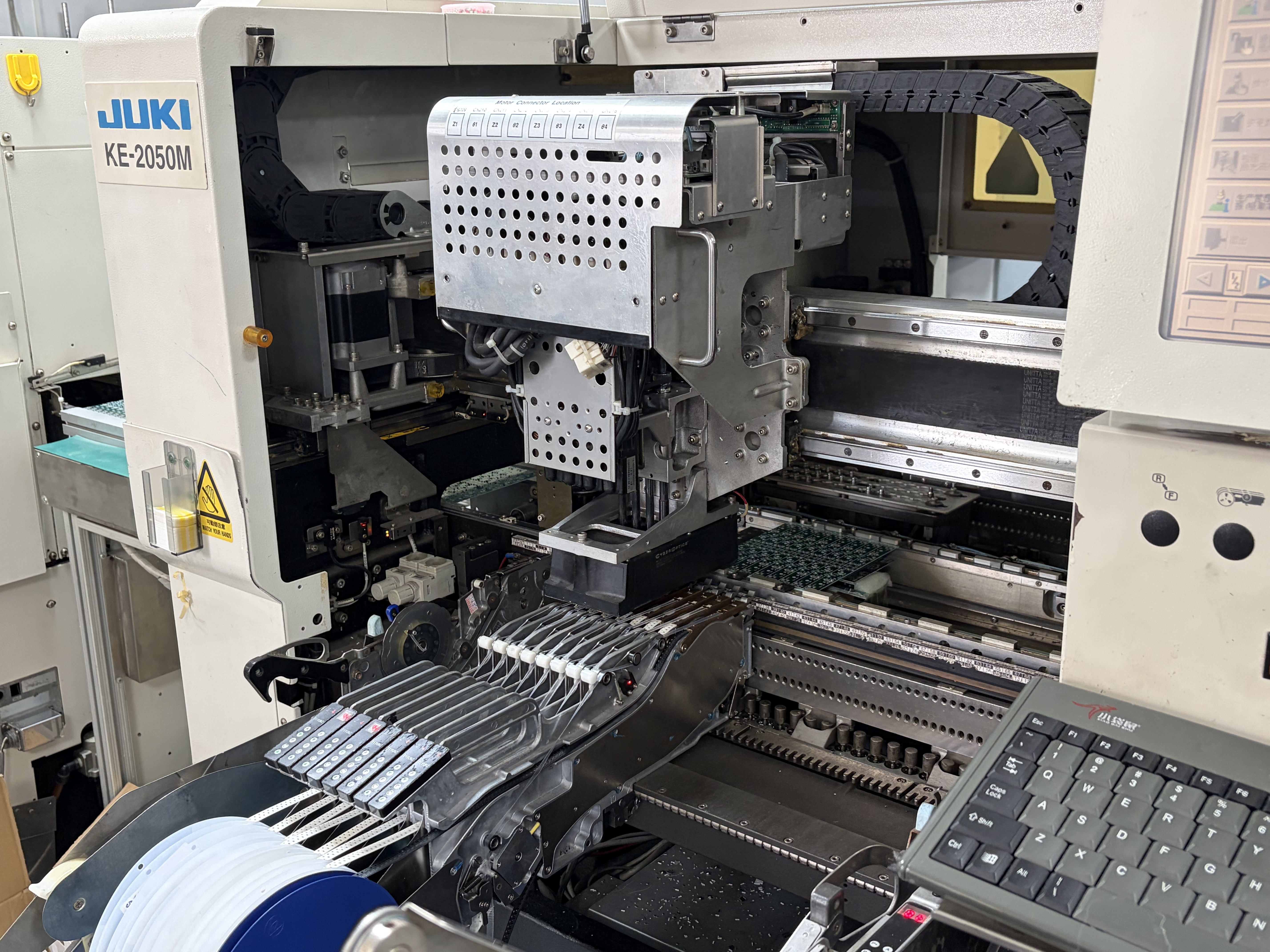
SMT placement / 5-second clip
See component placement in motion
The placement head moves between the feeder area and the PCB panel. This short clip shows one assembly operation, not the complete manufacturing or test sequence.
Play, pause or move through the clip using the controls below. The video does not start automatically.
Component placement equipment operating over a PCB panel.
06 / Define what “tested” means
PCBA Inspection and Testing Requirements
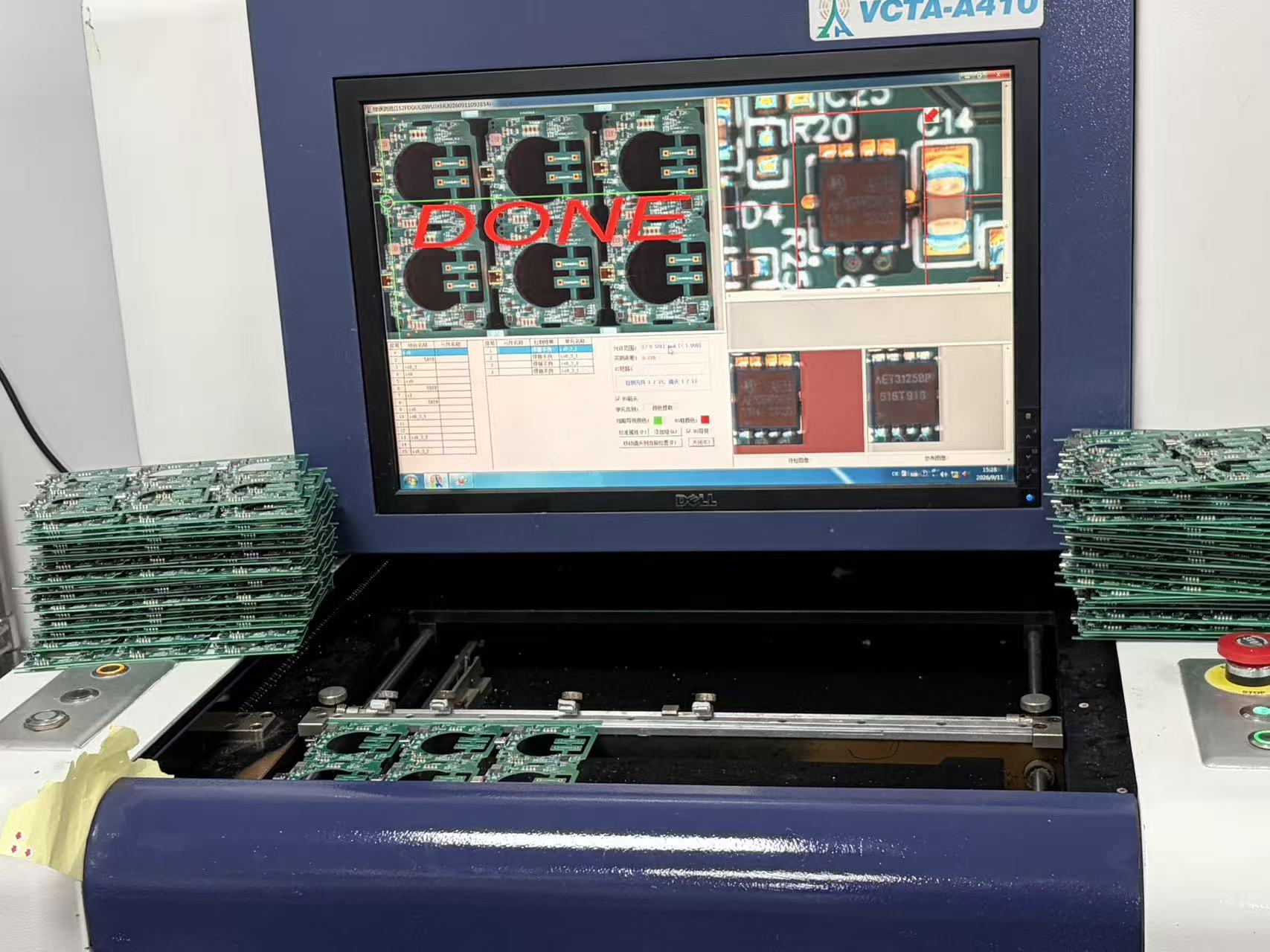
Different methods answer different questions. Visual or optical inspection can identify certain assembly defects, but it does not demonstrate every electrical function. A power-on check does not by itself confirm operation across all intended loads and conditions.
| Method | What it can assess | What must be agreed |
|---|---|---|
| Visual inspection / AOI | Visible placement, orientation and solder-related features, depending on inspection access and setup. | Inspection criteria, viewing coverage and treatment of flagged results. |
| SPI | Solder-paste deposits before component placement. | Whether paste inspection is required and how its process criteria are defined. |
| X-ray inspection | Selected hidden-joint features, such as bridging or voiding, where optical access is insufficient. | Packages to inspect, acceptance criteria and the relevant inspection coverage. |
| ICT / flying probe | Specified electrical connections and component-related measurements through accessible nodes. | Board access, fixture or program needs, limits and achievable test coverage. |
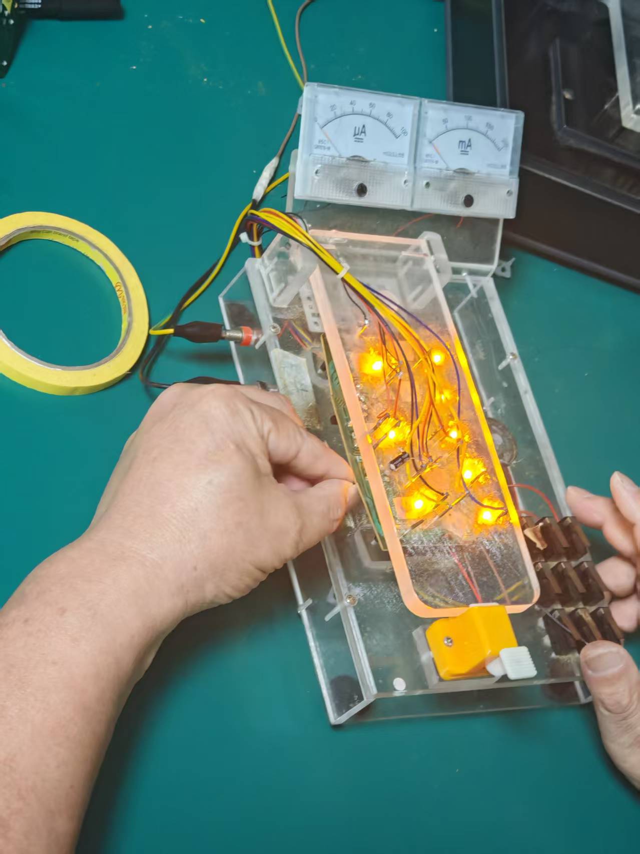
| Functional testing | Specified behavior under defined power, input, output and load conditions. | Test sequence, fixtures, firmware, reference units, pass/fail limits and record format. |
| Programming | Loading the approved software image and performing the agreed verification. | File version, programming interface, configuration data and verification method. |
Electrical acceptance
Define the conditions, not just “power on”
A functional-test brief should name the supply voltage, inputs, loads and expected outputs. Specify the limits for each measurement and the connections available to the fixture.
If programming is required, include the approved image and version. Agree who supplies the fixture and what test records will accompany each build.
If an acceptance standard is required, identify its applicable revision and class rather than writing only “IPC compliant.” The OEM’s finished-product safety, regulatory and environmental validation remains a separate responsibility unless explicitly included in a written agreement.
07 / Prototype to repeat orders
Make the Prototype a Useful Production Reference
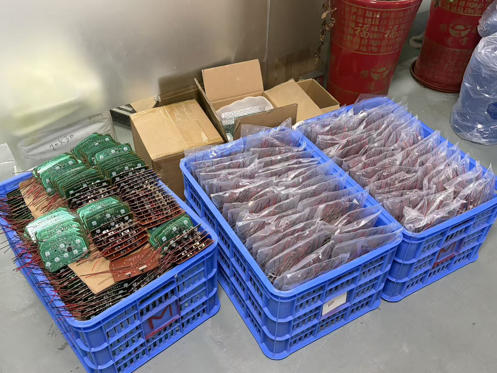
A prototype is most useful when it represents the intended components, assembly revision and installation conditions. Ask for sample and production quantities separately, and identify anything that is deliberately different in the prototype build.
At sample approval
Evaluate the circuit against your electrical requirements. Check enclosure fit, connector access, display alignment and user-input behavior. Record any deviations instead of relying on a verbal sign-off.
At production release
Freeze the approved BOM, drawings, firmware and inspection plan. Decide how engineering changes, alternate components and material shortages will be approved for subsequent orders.
Specify any required serial or lot identification, test records, packaging and shipping protection. Include moisture-sensitive or mechanically fragile parts in the handling discussion. Required quantities, component availability and the agreed test setup—not a generic website promise—determine the feasible production schedule.
08 / A quote you can compare
What Affects the Cost of a PCBA?
Board size alone is not enough to price an assembled circuit. Component cost, assembly complexity and verification requirements can change the quotation substantially. Compare quotes against the same released files and the same responsibilities.
- Boards and components
- Board construction, manufacturer part numbers, availability, approved alternatives and any customer-supplied material.
- Assembly work
- Number of placements, assembly sides, package mix, through-hole operations and special handling.
- Setup and validation
- Stencil or tooling, programming setup, fixtures, inspection coverage and functional-test development where included.
- Order and delivery scope
- Prototype and production quantities, repeat-order assumptions, packaging, integration and requested delivery terms.
Ask which charges are one-time and which repeat with each order. A lower unit price may exclude fixtures, programming, material procurement or tests included elsewhere. A PCBA enquiry should receive a project-specific quotation; this page does not provide an automatic price.
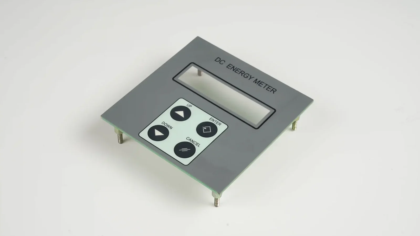
09 / Where electronics meets the operator
PCBA, Membrane Switch and HMI Integration
A correctly assembled board can still be difficult to install if its interface was designed in isolation. Coordinate the electronics with the front panel before the enclosure and tooling are fixed.
Membrane switch to board
Agree the circuit tail exit, mating connector, contact side, pinout, insertion access and bend space. Keep the key matrix and host-board interface consistent.
Silicone keypad to PCB
Align the contact pattern, keypad locating features, support and installed compression. Keep components clear of the key movement and enclosure features.
Display and touch interface
Review connector reach, display-window registration, total stack height and the electrical interface. Identify controller and firmware responsibilities separately.
Complete operator front panel
Coordinate the decorated surface, input layer, electronics, mounting and connection as a physical assembly. Agree the boundaries of any wider system work.
10 / Begin with the operating conditions
PCBA Requirements for OEM Equipment
Describe what the equipment does, where it operates and what happens if the interface fails. These application discussions help define the board and front-panel requirements; they are not a claim of approved projects or sector-specific certification.
Industrial controls
Define I/O connections, supply conditions, service access and the enclosure environment. If shielding or protective measures are needed, review the complete installed system.
Instrumentation
Identify signal interfaces, calibration responsibilities and the required test conditions. Separate board-assembly checks from measurement accuracy validated at system level.
Home appliances
Coordinate keypad operation, display visibility, wiring and mounting space. Specify heat, moisture and cleaning exposure at the installed interface.
Kiosks and vending equipment
Review repeated use, connector retention, display alignment and how a service technician accesses the board. Define which parts can be replaced independently.
For regulated or safety-critical equipment, send the required qualification and documentation scope before supplier selection. An industry label or a generic assembly inspection is not evidence of finished-device compliance.
11 / Your quotation package
What to Send for a PCB Assembly Quote
Use a clearly identified revision for the files below. If some information is not ready, say what is missing so the first discussion can distinguish an initial feasibility review from a production-ready quotation.
| Send or specify | Include these details |
|---|---|
| Board manufacturing data | Gerber with drill data, or another agreed export format; board outline, dimensions, stack-up and fabrication notes. Confirm file compatibility before sending an alternative data format. |
| Bill of materials | Manufacturer, full part number, reference designator, quantity, package, do-not-fit positions and approved alternatives. |
| Placement & assembly data | Pick-and-place / centroid file with coordinates, rotation and board side; assembly drawings with polarity, connector orientation and special instructions. |
| Quantity & material ownership | Prototype quantity, expected production batches, requested schedule, customer-supplied parts and sourcing requests. |
| Inspection, programming & tests | Required checks, acceptance criteria, firmware version where applicable, fixture responsibility, test procedure and reporting needs. |
| Mechanical & interface files | Enclosure drawing, keypad or display details, mounting references, connector pinout, cable routing and environmental requirements. |
Start with your board and BOM.
Tell us what you need assembled, what you will supply and what the finished board must do. Add the HMI or enclosure drawings when integration is part of the project.
The enquiry button opens JASPER’s existing RFQ page. Include “PCBA” in the project details and share your drawing package using the available file or file-link field. No price or production slot is confirmed simply by sending an enquiry.
12 / Questions & answers
PCB Assembly FAQ
What is the difference between a PCB and a PCBA?
A PCB is the fabricated circuit board without assembled electronic components. A PCBA is the board with components mounted and electrically connected. The accepted order must also define the required inspection, testing and any programming; those requirements are not established by the term PCBA alone.
What files are needed for a PCB assembly quotation?
Start with board manufacturing data, a BOM with manufacturer part numbers, a placement file and an assembly drawing. Include quantities, sourcing responsibility, required inspection and tests, and any enclosure or front-panel drawings. If a file is not ready, identify the gap for the initial review.
How do SMT and through-hole assembly differ?
SMT components attach to surface pads. Through-hole component leads pass through holes in the board. A mixed-technology assembly uses both. The required method depends on the components, layout, mechanical requirements and approved assembly process.
Can I request assembly using customer-supplied components?
Yes, you can include a customer-supplied-material request in your enquiry. List exactly what you plan to supply and what you want sourced. The accepted quotation must confirm whether that arrangement is supported, together with quantities, handling, shortage responsibility and treatment of unused material.
Does a turnkey PCBA request include firmware and box build?
Not automatically. Turnkey commonly refers to a sourcing and assembly arrangement, but its exact meaning must be defined in the quotation. Firmware development, programming, functional testing, enclosures and full-system integration should each be specified separately.
Is AOI enough to prove that a board works?
No. Automated optical inspection checks specified visible assembly features within its coverage. It does not verify every electrical function or hidden connection. Electrical and functional checks need a separate test plan with suitable access, equipment, conditions and pass/fail criteria.
Can a PCBA connect to a membrane switch or silicone keypad?
A board can be designed to connect to a membrane-switch tail or to support a silicone-keypad contact layout. Review pinout, connector orientation, contact registration, key travel, board support and enclosure clearance together. The approved drawings define the actual construction.
Can I request prototype and production quantities together?
Yes. Provide the sample quantity, likely batch quantities and expected revisions so the enquiry can separate prototype work from repeat production. Feasibility, material availability, setup requirements and schedule must be confirmed for the project; no universal minimum order or lead time is stated here.
How should alternative components be approved?
State your substitution policy in the BOM or purchasing notes. An alternative should be checked for electrical characteristics, package fit and other applicable requirements, then approved through the agreed change process before use. Matching a nominal value or footprint alone is not enough.
Does a PCBA include finished-product certification?
No. Assembling or testing a board does not by itself certify the finished equipment. Specify any applicable standards, documentation and qualification requirements before the project is accepted. Device-level safety, regulatory and environmental validation must have a clearly assigned owner.