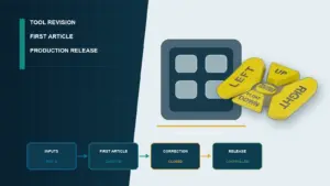
Approve a custom membrane switch sample only after it clears ten objective checks: drawing lock-down, certified materials, CMM-verified dimensions (±0.1 mm critical), dome force inside 280–340 g, contact resistance ≤100 Ω, overlay adhesion ASTM D3359 4B+, IP rating per IEC 60529, and a signed First Article Inspection (FAI) report. Skipping any one of these is how OEMs end up with field returns.
- 1. Why Sample Approval Decides Production Risk
- 2. The 10-Point Sample Inspection Framework
- 2.1 Drawing & Artwork Lock-Down
- 2.2 Material Certificates and RoHS / REACH Traceability
- 2.3 Dimensional First-Article Inspection
- 2.4 Tactile Dome Force and Snap Ratio
- 2.5 Actuation Life and Force Decay
- 2.6 Electrical Performance — Contact, Insulation, ESD
- 2.7 Graphic Overlay Quality
- 2.8 LED and Backlight Uniformity
- 2.9 Environmental Performance and Sealing
- 2.10 Documentation Pack and Golden-Sample Retention
- 3. Step-by-Step Sample Approval Process
- Step 1 — Freeze the Drawing Package Before Tooling
- Step 2 — Receive the Pilot Sample Lot of 15–30 Pieces
- Step 3 — Run the 10-Point Inspection in Order
- Step 4 — Resolve Deviations Through a Signed Deviation Log
- Step 5 — Sign Off the Golden Sample and Authorize Tooling Release
- 4. Red Flags That Should Halt Production Release
- 6. What to Do Next
A sample membrane switch that “looks right” can still fail in production. The custom membrane switch sample stage is where every assumption in the drawing meets physical reality — printed silver traces, snap domes, polyester overlays, 3M adhesives, embedded LEDs. Once an OEM signs off, the manufacturer locks BOM and tooling; later changes cost 4–10× more than catching them now. Quality and project managers can use a 10-point inspection framework backed by IPC, UL, IEC, and ASTM standards.
1. Why Sample Approval Decides Production Risk
The global membrane switch market reached USD 2.16 billion in 2023, growing at 4.6% CAGR through 2030 (Grand View Research, 2024). Medical, automotive, and industrial OEMs run programs where a single field recall can cost USD 0.5–5 million in rework, scrap, and warranty payouts. U.S. Consumer Product Safety Commission data shows user-interface defects — sticking keys, illegible overlays, contact failures — account for a meaningful share of small-appliance recalls.
The custom membrane switch sample (pilot sample, prototype, or first article) is the only point where the OEM holds full control. Before this gate, drawings can be revised. After it, tooling is set, raw-material POs issued, and process parameters frozen. A 2 mm tail-cable offset caught at the sample stage costs hours; the same defect at production qualification costs weeks; in the field, it costs the contract.
A disciplined first article inspection (FAI) is what audit-driven industries — ISO 13485 medical, IATF 16949 automotive, MIL-STD aerospace — require. The 10-point checklist in §2 maps to those audit clauses so one inspection serves both engineering acceptance and the supplier quality file.
2. The 10-Point Sample Inspection Framework
The framework below covers every layer of a membrane switch stack: graphic overlay, embossed key area, spacer, top circuit, bottom circuit, rear adhesive, plus LED, light-guide, or shielding sub-assemblies. Each criterion has a measurable acceptance band and a traceable standard.
| # | Criterion | Key parameter | Standard |
|---|---|---|---|
| 1 | Drawing & artwork lock-down | All layers at released revision | Internal change control |
| 2 | Material certificates | RoHS / REACH / cert numbers | EU 2011/65, EC 1907/2006 |
| 3 | Dimensional FAI | ±0.1 mm critical, ±0.25 mm non-critical | ISO 2768 medium |
| 4 | Dome force & snap ratio | 280–340 g; 40–60% snap | Snaptron / Hoffmann curves |
| 5 | Actuation life | ≥1,000,000 cycles, <15% decay | IEC 60068-2-6 |
| 6 | Electrical performance | Contact R ≤100 Ω; Insulation R ≥100 MΩ | IEC 60512 family |
| 7 | Overlay quality | ASTM D3359 4B; UL 969 chemical | UL 969, ASTM D3359 |
| 8 | LED uniformity | ≤30% brightness delta; CIE binning | CIE 1931 / IES LM-79 |
| 9 | Environmental & sealing | IP65 minimum; -20 to +70 °C | IEC 60529, IEC 60068 |
| 10 | Documentation pack | FAI report + golden sample | AS9102 / PPAP analog |
2.1 Drawing & Artwork Lock-Down
Before any inspection begins, confirm the sample matches the released drawing set: graphic overlay PDF revision, circuit Gerber revision, embossing detail drawing, and bill of materials all carrying the rev number greenlit at design review. Some manufacturers ship samples built to an earlier rev “to save time” — a habit that quietly invalidates the FAI.
Good signal: Build documentation lists each artwork file by filename, revision, and hash, matchable against the released package. Red flag: Sample arrives with no rev callout, or the rev on the artwork PDF differs from the rev burned into the silver-print screen.
2.2 Material Certificates and RoHS / REACH Traceability
Every functional layer needs a paper trail. The overlay film (Autotex F157, Autotex V200, or Lexan HP92S) requires the lot certificate from Macdermid or Sabic. The adhesive (3M 467MP, 3M 468MP, or 3M VHB 5952) needs a lot number matching what was applied to the sample. Silver paste, dielectric ink, PET substrate, and snap domes (Snaptron, Hoffmann) each carry RoHS 2011/65/EU and REACH 1907/2006 declarations.
Good signal: Single PDF pack bundles certificates of conformity for overlay, adhesive, ink, substrate, and dome, each with traceable lot numbers and supplier signatures. Red flag: Generic supplier letters with no lot numbers, expired RoHS dates, or a missing certificate for the rear adhesive — the most common gap.
2.3 Dimensional First-Article Inspection
Dimensional FAI uses calipers, pin gauges, and a coordinate measuring machine (CMM) where tolerances tighten below ±0.1 mm. Critical dimensions — outline cut, mounting-hole positions, tail-cable centerline, connector pitch, key-pitch — hold ±0.1 mm. Non-critical dimensions hold ±0.25 mm under ISO 2768 medium. A common defect is a tail-cable centerline 1.5 to 3 mm off the drawing; it rarely shows up visually but jams the connector during assembly.
Good signal: Signed FAI report shows measured value, nominal, tolerance, and pass/fail status for every critical dimension across at least five samples. Red flag: “Visual check passed” with no numeric values, or a 1+ mm deviation justified as “within manufacturing capability”.
2.4 Tactile Dome Force and Snap Ratio
Tactility is the most subjective spec on the drawing and the most likely to drift. Stainless steel snap domes from Snaptron publish standard ratings such as 3 N (≈305 g) and 5 N (≈510 g); custom-tuned domes in the 2.7–3.4 N range (≈275–345 g) are typical for industrial keypads. The snap ratio — actuation-to-return force delta — governs felt “click” and sits at 40–60%. Polydome (embossed PET) keys land at 150–220 g with a softer 25–40% ratio. Measure with a calibrated force gauge (Mark-10, Imada DS2) at three points per key, averaging five domes per key style.
Good signal: Force-displacement curves per key style, with mean and standard deviation across at least 10 samples, inside the drawing’s specified band. Red flag: “Feels right” written on the inspection sheet, a single value with no spread, or domes outside ±10% of spec.
2.5 Actuation Life and Force Decay
Industrial and medical membrane switches typically spec one million actuations minimum. Some buyers ask for two; medical-grade keypads sometimes spec five. The accepted test follows IEC 60068-2-6 or a manufacturer-internal cycling fixture at 2 Hz with a force 20–30% above nominal. After one million cycles, contact resistance shall remain ≤100 Ω and dome force shall not decay more than 15%. The test is destructive and takes 6 to 14 days, so it runs on three to five sacrificial samples from the pilot lot — not on the golden sample retained for production reference.
Good signal: Cycling report from a calibrated rig logs cycle count, applied force, ambient conditions, plus pre- and post-test resistance and force readings. Red flag: Cycle test waived “because the drawing didn’t require it” when it did, or a report with no environmental conditions logged.
2.6 Electrical Performance — Contact, Insulation, ESD
Three electrical numbers anchor every inspection. Closed-circuit contact resistance — measured through the key dome and silver trace — accepts ≤100 Ω, with 50 Ω achievable on copper-flex circuits. Insulation resistance, between adjacent traces or to chassis ground, must hit ≥100 MΩ at 100 VDC under IEC 60512. ESD immunity, where specified, follows IEC 61000-4-2 contact discharge at ±4 kV or ±8 kV depending on the end product’s exposure.
Good signal: Test rig uses a calibrated source/meter — Keysight 34465A or similar — with results logged per key, plus a continuity test on a flying-probe or bed-of-nails fixture. Red flag: Spot-check on one key only, readings from an uncalibrated handheld DMM, or no insulation-resistance result.
2.7 Graphic Overlay Quality
End users see, touch, and clean the overlay; that’s why it absorbs the most warranty stress. Inspection covers four things: print registration (color-to-color and color-to-die-cut within ±0.15 mm), ink adhesion per ASTM D3359 cross-cut at 4B minimum, abrasion and chemical resistance per UL 969, and legibility per ASTM F1842. The chemical panel always includes isopropanol, ethanol, and mild bleach. Medical OEMs add CaviCide and hydrogen peroxide. Specify yours up front — back-fitting chemical tests after sample approval is awkward.
Good signal: Cross-cut photos showing 4B or 5B, UL 969 chemical-soak report on same-print-run coupons, legibility report with illuminance and contrast values. Red flag: Visible misregistration, ink lifting on a Scotch-tape pull, or no chemical-test data for chemicals the field actually uses.
2.8 LED and Backlight Uniformity
For backlit keypads, brightness uniformity decides low-light readability — and it’s the single most under-inspected criterion. With the LED driver at nominal current, the brightest key should emit no more than 30% above the dimmest. Measure with a luminance meter (Konica Minolta LS-100 or equivalent) at 0.3 m. Color binning per CIE 1931 chromaticity coordinates should hold across every LED in one assembly. One LED on a different bin shows up as a visibly green or pink tint next to its neighbors. End users notice immediately.
Good signal: Photometric report with luminance per key in cd/m² and chromaticity per LED, plus light-guide film placement matching the drawing. Red flag: “All keys lit, looks fine” sign-off, mixed LED bins on one assembly, or no LED supplier datasheet for traceability.
2.9 Environmental Performance and Sealing
Where the keypad faces moisture, oil, dust, or temperature swings, environmental qualification is non-negotiable. IP rating per IEC 60529 — IP65 for industrial sealed overlays, IP67 for fully immersible — is verified on a dust chamber and water-spray fixture, not declared on paper. Temperature endurance follows IEC 60068-2-1, -2-2, and -2-30, with operating bands of -20 °C to +70 °C industrial or -40 °C to +85 °C automotive. MIL-STD-810H applies where defense or aerospace customers have written it in.
Good signal: Independent test-lab report (Intertek, TÜV, UL, SGS) for IP rating and temperature/humidity profile; salt-fog report per ASTM B117 if specified. Red flag: “IP65 design” claimed with no chamber test, or temperature range “covers ambient” with no high/low-temperature verification.
2.10 Documentation Pack and Golden-Sample Retention
The final deliverable is the documentation pack itself — and it’s where many otherwise-clean sample programs lose audit points. A defensible pack contains: signed FAI report with every parameter from §2.1 through §2.9 measured and pass/fail-flagged; material certificates with lot numbers; FMEA and control plan extracts (mandatory under IATF 16949); cycle-life and environmental test reports; a deviation log of any agreed exceptions; and at least three retained golden samples — one each for buyer incoming inspection, manufacturer QA bench, and a sealed reference. Automotive programs add a PPAP submission. Medical adds DHR (Device History Record) traceability.
Good signal: Documentation pack delivered as a single bound PDF plus the physical samples, with an index page listing every attached test report. Red flag: Verbal claim of testing with no report attached, or no retained golden sample identified by serial number.
3. Step-by-Step Sample Approval Process
Step 1 — Freeze the Drawing Package Before Tooling
Before the manufacturer cuts a tool or burns a screen, the buyer issues a controlled drawing package: outline, circuit Gerber, overlay PDF with PMS color callouts, BOM with approved sources, embossing detail, connector pinout, and the spec document linking each requirement to a standard. The package gets a release rev (e.g., Rev D, 2026-04-15) and a sign-off list.
Step 2 — Receive the Pilot Sample Lot of 15–30 Pieces
Industry-standard pilot lot is 15 to 30 pieces — enough for destructive cycle-life testing (3–5 units), environmental conditioning (3–5 units), dimensional and electrical FAI (5 units), and 3 retained samples. Smaller lots force trade-offs between destructive and non-destructive checks. The lot ships with a packing list naming the drawing rev and build date.
Step 3 — Run the 10-Point Inspection in Order
Inspection runs §2.1 through §2.10 in sequence because earlier checks gate later ones — there is no point cycle-testing a sample whose dimensions are out of tolerance. A dedicated inspector logs each result on a controlled form. Where a result is borderline, the buyer’s engineering team decides whether to accept, accept-with-deviation, or reject.
Step 4 — Resolve Deviations Through a Signed Deviation Log
When a sample misses a criterion, the path forward is rework, design change, or a written deviation accepted by buyer engineering and quality leads. Each entry records the criterion missed, measured value, spec value, impact analysis, approver, and deviation duration (one lot, one PO, or permanent — the last requires a drawing update).
Step 5 — Sign Off the Golden Sample and Authorize Tooling Release
Approval is documented by signing a Golden Sample Acceptance Form that names the lot date, drawing rev, deviation log entries, and retained-sample serial numbers. From this gate forward, every production lot is inspected against the golden sample and the FAI report. Drawing changes after this gate require a controlled Engineering Change Notice (ECN) and often a re-sample.
4. Red Flags That Should Halt Production Release
Some sample-stage findings should pause approval until resolved, regardless of timeline pressure.
- Critical-dimension deviation above 1 mm without engineering analysis — usually points to a tooling error, not measurement noise.
- Dome force outside ±10% of spec — life-test results from in-spec parts do not transfer to out-of-spec parts.
- Missing RoHS or REACH declaration on any functional layer — blocks EU market access and audit closure.
- Adhesive lot certificate missing or expired — 3M adhesives have published storage windows; expired stock means the sample’s adhesion is not the production adhesion.
- No insulation resistance test result — a sample untested at ≥100 MΩ / 100 VDC is not electrically qualified.
- Cycle-life test waived without written buyer concurrence — the durability claim is unsubstantiated.
- No retained golden sample, or golden sample not labeled by serial number — nothing exists to inspect future lots against.
5. Frequently Asked Questions
How many membrane switch samples should an OEM request for first article inspection?
Plan for 15 to 30 pieces. That size supports destructive cycle-life testing on 3–5 units, environmental conditioning on 3–5 units, dimensional and electrical FAI on 5 units, and 3 retained golden samples. Below 15 forces the inspection team to choose between destructive and non-destructive testing.
What dome force range is acceptable for an industrial membrane switch?
Most industrial keypads spec stainless snap domes at 280 to 340 g actuation force with a 40–60% snap ratio, measured per Snaptron or Hoffmann published curves. Polydome (embossed PET) keys land lower at 150–220 g with a softer 25–40% ratio. Deviation above ±10% is grounds for rejection.
Which standards apply to membrane switch sample inspection?
Twelve standards do the heavy lifting: IPC-2221 and IPC-6013 (circuit and flex), UL 969 and UL 746C (overlay and substrate), IEC 60068 family (environmental), IEC 60529 (IP rating), IEC 60512 (electrical), ASTM D3359 (adhesion), ASTM F1842 (legibility), plus ISO 13485, IATF 16949, or MIL-STD-810H per vertical.
How is contact resistance measured on a membrane switch sample?
A calibrated source-meter — Keysight 34465A or equivalent — applies a small DC current through the closed dome and silver trace; the voltage drop yields resistance. Acceptance for silver-paste circuits sits at ≤100 Ω closed; copper-flex circuits reach ≤50 Ω. Insulation resistance between adjacent traces is measured at 100 VDC and must exceed 100 MΩ.
What is a Golden Sample and why does it need a serial number?
A Golden Sample is an approved physical reference unit retained by both buyer and manufacturer after sample approval. Every future production lot is inspected against it for visual, tactile, and dimensional consistency. Serial-numbering prevents accidental substitution and ties the sample to a specific FAI report and drawing revision.
How long does a complete membrane switch sample approval cycle take?
Eight to fourteen weeks is realistic for a straightforward design: 1–3 weeks for artwork lock-down, 3–5 weeks for tooling and pilot build, 1 week for international shipping, and 2–6 weeks for OEM-side qualification including cycle and environmental testing. Designs with multiple LED colors, IP67 sealing, or medical traceability extend toward 16 weeks.
Is a 2 mm tail-cable position deviation acceptable on a pilot sample?
Only after engineering analysis confirms the connector still mates and assembly clearance still holds. The buyer accepts with a written deviation entry and requires the drawing or tool be corrected for the next lot. Accepting a 2 mm offset without root-cause investigation is the most common preventable assembly-line stoppage.
What goes into a defensible First Article Inspection report?
Eight elements: measured value plus pass/fail flag for every critical dimension, material lot certificates, contact and insulation resistance per key, dome force statistics across at least five samples, cycle-life data, environmental test data, photographs from at least four angles, and the signature block from manufacturer QA and buyer quality lead.
Should sample inspection differ for medical versus industrial membrane switches?
Yes. Medical adds ISO 13485 DHR traceability, biocompatibility data per ISO 10993 where the overlay contacts the patient, and tighter cleaning-chemical panels (CaviCide, hydrogen peroxide, isopropanol). Automotive adds IATF 16949 PPAP submission plus thermal shock per IEC 60068-2-14. Industrial typically holds at ISO 9001 with IP65 sealing.
Who signs off the membrane switch sample approval?
At minimum, three parties: the buyer’s design engineering lead (drawing is technically correct), the buyer’s quality lead (inspection results pass), and the manufacturer’s QA lead (build is repeatable in production). Programs under IATF 16949 add a supplier quality engineer; medical programs add a regulatory affairs reviewer.
6. What to Do Next
Walk every custom membrane switch sample through the ten checks in §2 before signing the Golden Sample Acceptance Form, and keep the deviation log explicit — every accepted exception, every rework, every retest. A printable version of this 10-point FAI checklist is available at jasperele.com/blog/custom-membrane-switch-sample-approval/checklist.
Disclosure: JASPER Electronics authored the technical framework as a custom membrane switch and keypad manufacturer based in China. The framework is presented neutrally and applies to any qualified supplier.
Ready to Start Your Project?
Tell us about your membrane switch, keypad, or graphic overlay requirements. Our engineering team will review your specifications and provide a detailed quote.