
WEARABLE ELECTRODE PATCH MANUFACTURING
Custom Wearable Medical Electrode Patches
JASPER is a wearable electrode patch manufacturer for custom flexible circuits, distributed contact sites and converted layers in customer-defined body-worn devices.
JASPER manufactures the released flexible construction. The customer owns anatomical placement, skin-contact suitability, wear protocol, motion performance, electronics behavior, clinical use and finished-device approval.
- Flexible body-worn layouts
- Controlled bend and tail zones
- Project-defined liner sequence
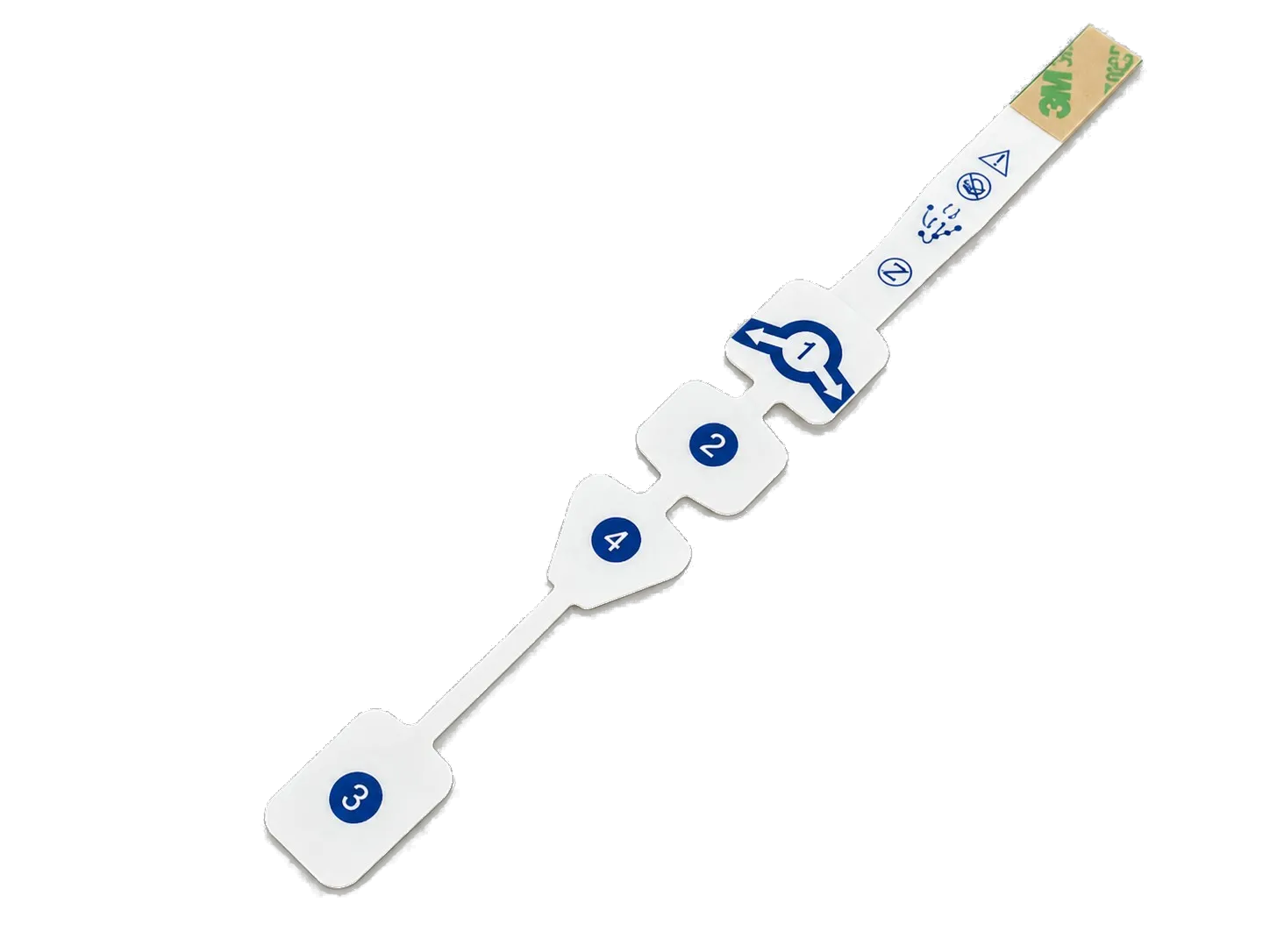
MECHANICS BEFORE CLAIMS
Engineer a patch that can be placed, connected and handled as designed
A wearable medical electrode patch sits at the intersection of flexible circuitry, converted materials, placement workflow and moving anatomy. The drawing must show where the part may bend, where it must not bend and how each layer is applied.
JASPER can manufacture to
- Customer-defined flexible electrode and trace geometries
- Screen printing, dielectric coverage, die cutting and layer registration
- Project-specified adhesive, liner, spacer and protective-layer conversion
- Printed tails, local reinforcement and electronics contact zones
- Prototype iterations and repeat builds to approved artwork and BOM
The device team defines and validates
- Anatomical location, placement method and body-motion envelope
- Patient-contact materials, skin preparation and biocompatibility evidence
- Wear duration, removal, sweat exposure and comfort requirements
- Signal quality, motion artifact, electronics and wireless-system performance
- Clinical validation, labeling, risk controls and regulatory release
DESIGN ROUTES
Separate the body-worn patch into mechanical zones
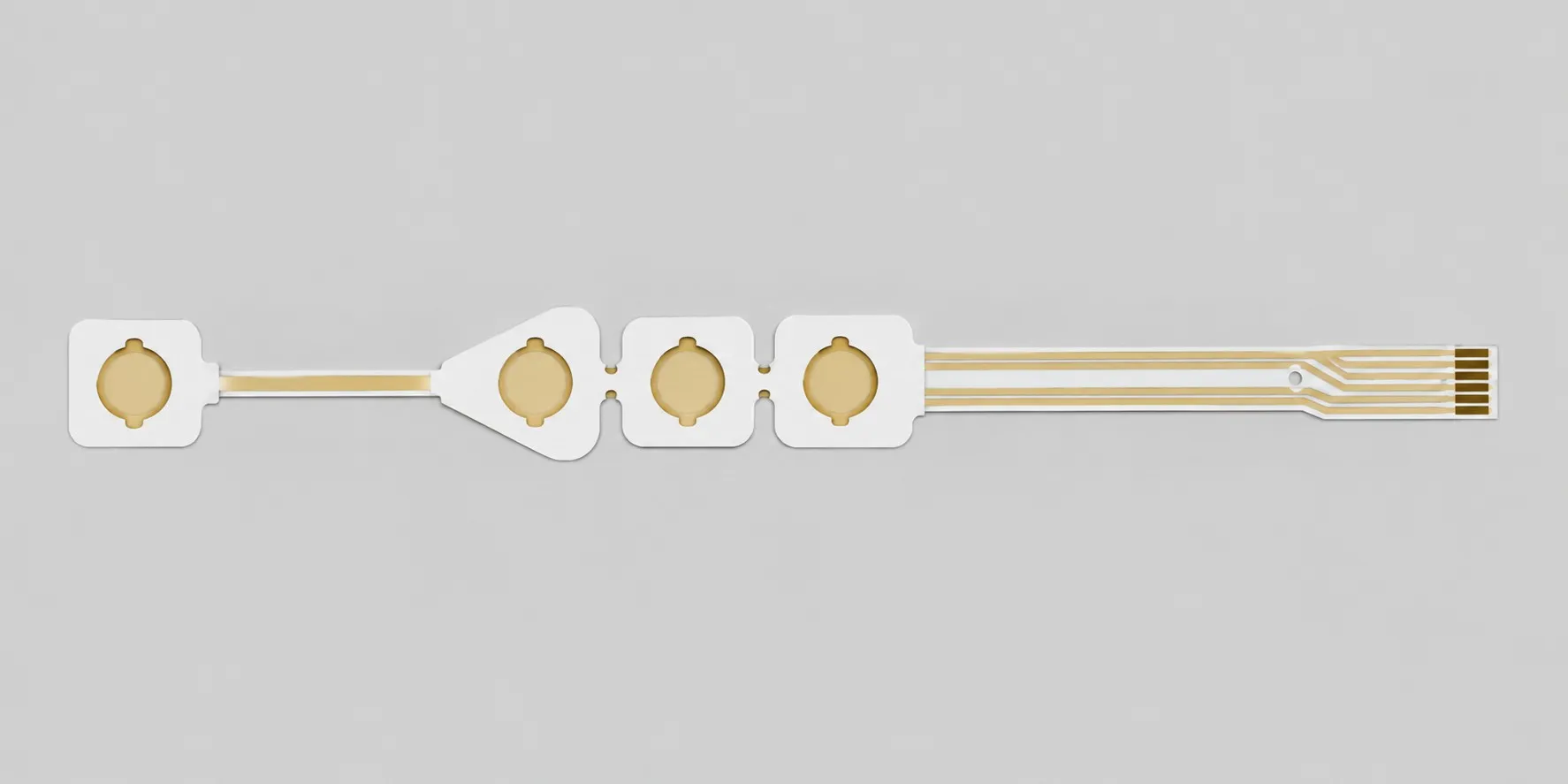
A uniform laminate rarely behaves well across every part of a wearable assembly. Contact fields, flex bridges and the electronics or connector zone should be specified according to their different jobs.
01 / CONTACT FIELD
Distributed electrode sites
02 / FLEX BRIDGE
Compliant printed interconnect
03 / DEVICE INTERFACE
Reinforced tail or electronics zone
BODY-WORN STACK CONTROL
Treat placement and removal as design inputs
Liner splits, tabs, layer transitions and adhesive-free handling zones can determine whether a patch is placed according to the approved map without stretching, folding or contaminating a contact area.
DATUMS
Preserve the intended electrode map
BEND ZONES
Route traces through controlled flex regions
LINERS
Sequence release and application
REMOVAL
Plan the end of the use cycle
CONTROLLED PROJECT FLOW
Develop the wearable patch around real handling and motion
- 01
Map use mechanics
Share placement, motion zones, application sequence, electronics interface and customer-owned patient-contact requirements.
- 02
Review the stack
Check printed routing, flex transitions, adhesive coverage, liner splits, die lines and layer registration together.
- 03
Build prototypes
Manufacture one controlled revision for customer placement, movement, signal, comfort and device-integration studies.
- 04
Close revisions
Resolve artwork, material, liner, handling, test and documentation changes before the production definition is frozen.
- 05
Repeat the approved build
Control released artwork, BOM, process sequence, inspection plan and golden sample through repeat production.
RFQ INPUTS
What to send a wearable electrode patch manufacturer
Include the way the patch is handled and placed, not only a DXF outline. Wearable DFM depends on mechanical transitions, liner sequence and the interface to the electronics.
Send the Current Revision- Dimensioned electrode map and complete patch outline
- Trace, dielectric and exposed-contact artwork
- Body location, placement and motion assumptions
- Carrier, ink, contact, adhesive and liner requirements
- Bend zones, stiffeners, tail and electronics interface
- Application and removal sequence with handling tabs
- Customer-owned electrical, mechanical and material test criteria
- Prototype quantity, forecast volume and development schedule
BUYER QUESTIONS
Wearable electrode patch manufacturing FAQ
Wear duration and patient performance are not generic properties of a printed circuit. They depend on the complete customer-approved stack and finished-device evidence.
Can JASPER manufacture a custom wearable medical electrode patch?
JASPER can manufacture customer-defined flexible printed electrode circuits and converted patch layers when the geometry, materials, interface and assembly scope fit our processes. The quotation identifies the exact deliverable.
Can several electrode sites be integrated into one wearable patch?
Yes, distributed contact sites and routed channels can be reviewed from released artwork. Their location, function, signal behavior and anatomical placement remain customer design and validation inputs.
Can the patch include a flexible tail for the electronics?
A printed tail, contact zone, stiffener or specified connector interface can be included within the quoted scope. The mating electronics and mechanical envelope must be defined by the customer.
Does JASPER guarantee long wear, sweat resistance or comfort?
No universal claim is made. Wear, sweat, comfort and removal behavior depend on anatomy, preparation, materials, geometry, environment and the validated finished device.
How should liner design be specified?
Provide the intended application sequence, liner split locations, pull direction, handling tabs, exposed areas and placement orientation. Prototype trials should verify the final sequence.
Can JASPER test bend or motion performance?
Project-specific mechanical or electrical checks may be quoted when the customer supplies a defined method, fixture, cycle, limit and sampling plan. Device-level motion validation remains customer-owned.
Who approves patient-contact materials?
The medical-device customer approves patient-contact materials and the supporting evidence for the intended use. JASPER manufactures the approved material stack within the documented scope.
START WITH EVIDENCE
Have a body-worn electrode layout and placement sequence?
Send the electrode map, flex zones, material stack, liner sequence, tail interface, customer-owned validation inputs and forecast. JASPER will review the construction as a manufacturable system.