A silicone keypad prototype should prove more than appearance. Before production, the OEM and supplier need approved evidence for molded dimensions, force-displacement behavior, contact position, return, enclosure fit, graphics, lighting, assembly, and the production process that will reproduce them. Tooling release should stop when the material, mating PCB, housing datums, critical dimensions, test conditions, or acceptance limits are still changing. A first molded sample is an engineering checkpoint, not automatic approval of the mold or production process. The release package should connect every approved sample to a controlled drawing, tool revision, cavity identity, material, process route, and test record.
For an OEM project that needs raised molded keys, conductive contacts, backlighting, laser-opened legends, or a supplied keypad module, start with the custom silicone rubber keypads product family. The commercial route can be chosen early, but the mold should not be released until the supplied boundary and approval evidence are explicit.
What Must Be Approved Before a Silicone Keypad Enters Production?
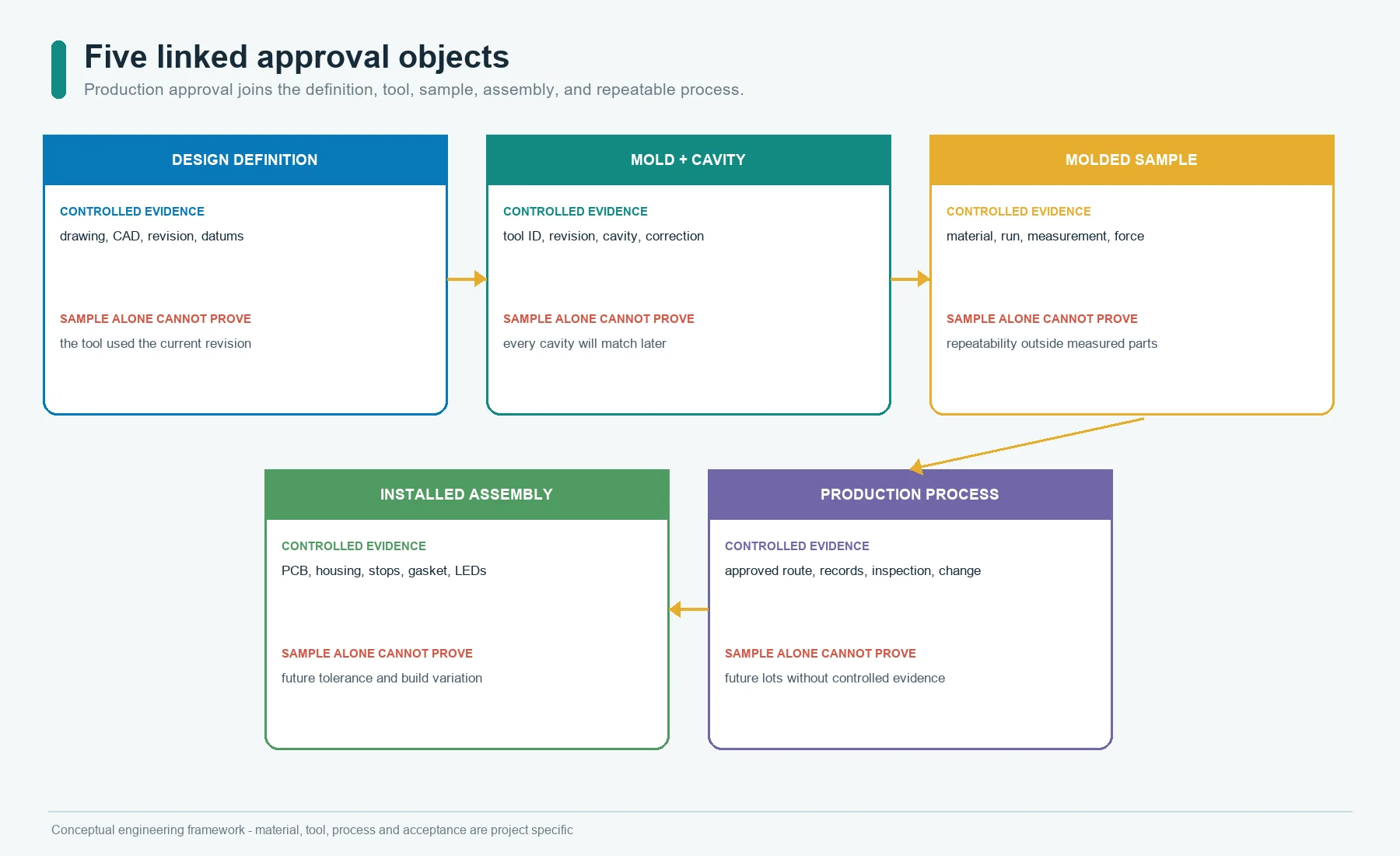
Production approval is a collection of linked decisions. It is not a single signed sample.
| Approval object | Evidence needed | What a visual sample cannot prove |
|---|---|---|
| Product definition | controlled 2D drawing, 3D model, revision, datums, mating parts | that the tool was built from the current revision |
| Material and cure route | approved material identity, color system, cure and post-cure responsibility | long-term behavior or repeatability |
| Molded geometry | dimensional report tied to tool and cavity | dimensions outside the measured sample |
| Key feel | force-displacement curves with fixture, speed, support, and conditioning recorded | repeatable peak, return, release, or bottoming behavior |
| Electrical action | contact location, circuit, test level, actuation point, and acceptance record | stable circuit closure in the final assembly |
| Surface and legends | color, gloss, texture, print or coating stack, laser artwork, inspection criteria | abrasion, cleaner, or light exposure durability |
| Lighting | powered assembly, LED and PCB revision, day/night criteria, viewing conditions | production light uniformity or optical aging |
| Assembly fit | current PCB, housing, fasteners, adhesive, gasket, and connector | fit after tolerance stack or production variation |
| Production process | tool revision, cavity record, material lot, process window, inspection plan | future lot consistency |
The governing question is simple: can another production lot be accepted from written requirements and measured data without asking someone to remember how the sample looked or felt?
Define Prototype, First Article, Golden Sample, and Production Approval
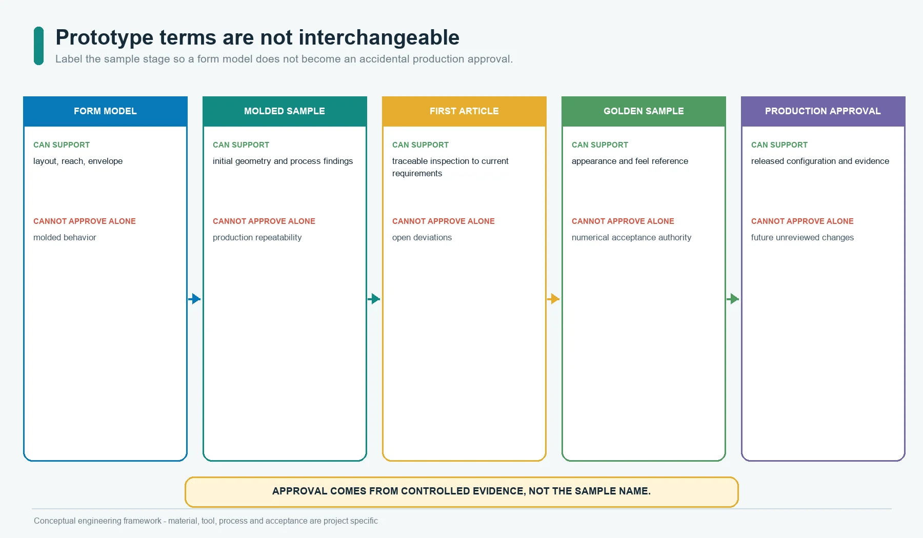
Teams often use the word prototype for several different objects. The ambiguity creates false approvals.
Non-production prototype
A non-production prototype may use machined, printed, cast, simplified, or substitute parts. It can answer layout, reach, key spacing, enclosure clearance, user-label, and architecture questions. It usually cannot establish molded shrinkage, final web behavior, production surface, flash, parting-line condition, or cavity repeatability.
Molded engineering sample
A molded engineering sample comes from a real mold or a development tool. It can expose molding, demolding, geometry, contact loading, flash, and force-curve problems. Its value depends on whether the intended material, process route, inserts, cure, post-cure, and measurement conditions are represented.
First article
A first article is a traceable part or set of parts inspected against the current controlled requirements. The report should identify the tool revision, cavity, material, process condition or approved window, part age or conditioning, measurement method, and drawing revision.
Golden sample
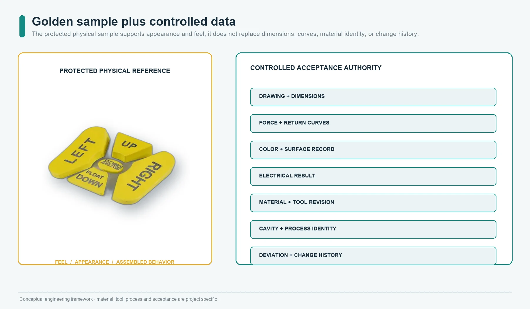
A golden sample is a protected physical reference for appearance, feel, or assembled behavior. It is useful, but it is not a substitute for numerical tolerances, artwork, color limits, force curves, electrical criteria, or a revision-controlled inspection plan.
Production approval
Production approval states that the product definition, tool, material, process, inspection, traceability, and change rules are accepted for repeat manufacturing. A beautiful first sample can still fail this gate.
Freeze the Inputs That Control the Mold
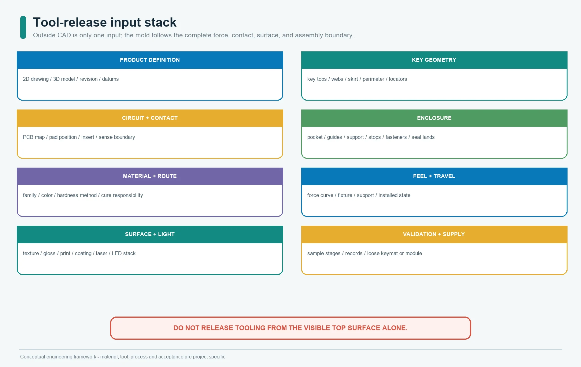
A silicone keypad mold should not be based only on the visible top surface. The complete force path and assembly stack influence the tool.
Minimum release inputs include:
- current 2D drawing and 3D model with matching revision;
- key center locations, key-top geometry, web sections, skirt, perimeter, and locating features;
- mating PCB or circuit contact map;
- enclosure pocket, guide, ribs, hard stops, supports, fasteners, and sealing lands;
- contact element type and loading method;
- material family, color, hardness test requirement, cure system, and restricted-substance requirements;
- free-state and assembled-state dimensions;
- key-force and travel targets with the measurement fixture defined;
- visible surface, texture, gloss, legend, coating, and lighting requirements;
- connector, tail, adhesive, gasket, spacer, and supplied-assembly boundary;
- prototype quantity, production quantity, validation plan, and required records.
If the PCB or enclosure is not mature, release only the work that can be changed without trapping the project in the wrong stack. Tooling can move quickly; a wrong datum can move even faster.
Assign Ownership Before Tool Design Starts
The RFQ should state who owns each decision and each physical item.
| Item | Possible owner | Approval question |
|---|---|---|
| Silicone material and color system | supplier, OEM, or shared | who approves a grade or supplier change? |
| Mold design and manufacture | supplier, toolmaker, or OEM-nominated source | who approves the concept and corrections? |
| Conductive insert or pill | silicone molder or separate supplier | how is identity and placement controlled? |
| PCB, FPC, or PET circuit | OEM, keypad supplier, or electronics supplier | which revision is used for fit and electrical approval? |
| Housing and hard stops | OEM mechanical team | who owns stack-up and installed preload? |
| Printing, coating, and laser | molder, decorator, or subcontractor | which process and acceptance evidence apply? |
| Assembly and test | keypad supplier, contract manufacturer, or OEM | where is final functional acceptance performed? |
| Validation | OEM, supplier, or independent laboratory | which party approves each result? |
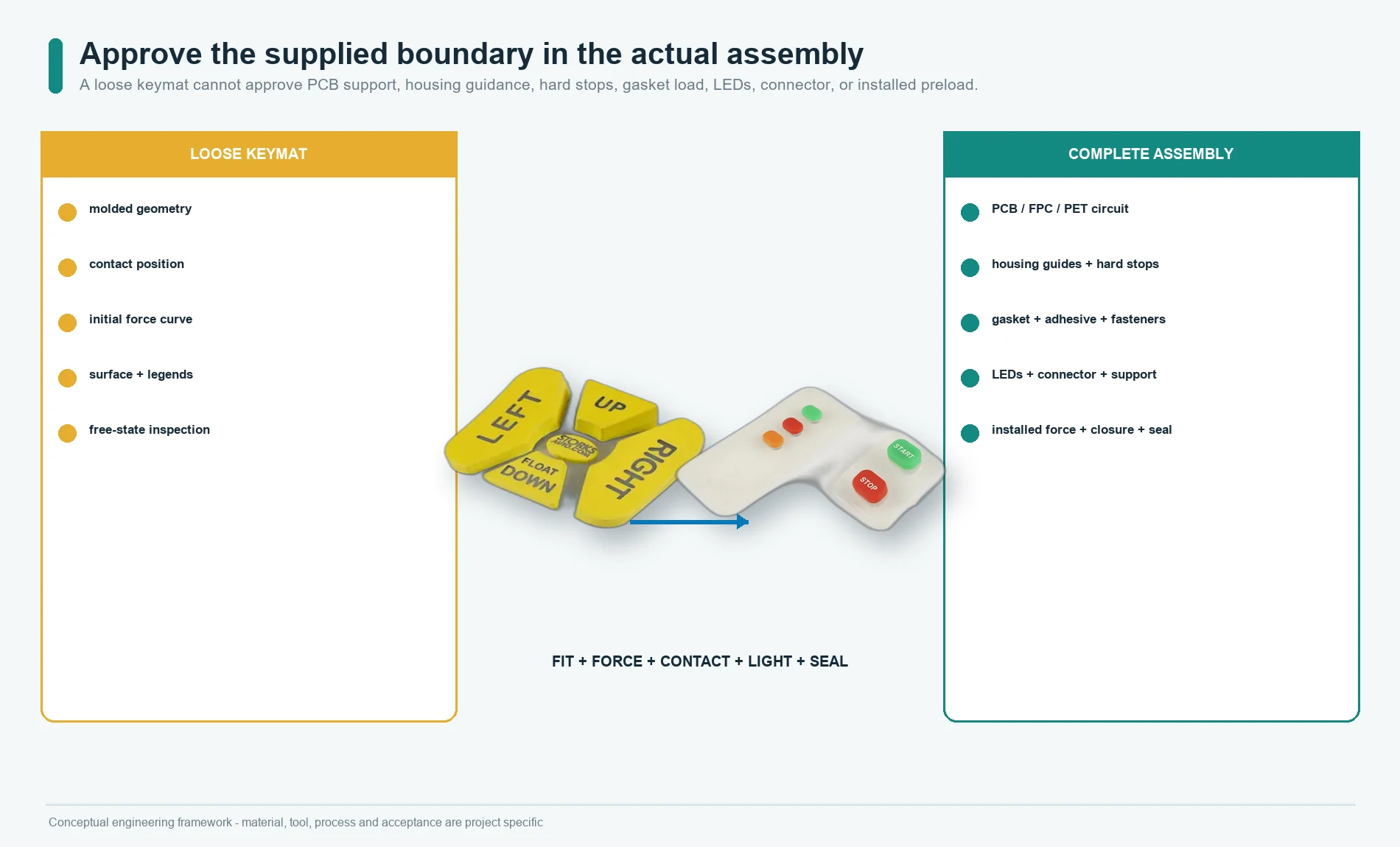
When the delivered item includes the rubber keymat, circuit, LEDs, connector, spacer, or final test, review the silicone keypad assembly boundary before tooling. The tool may be correct for a loose keypad and wrong for the installed module.
Choose the Molding Route From the Part and Material
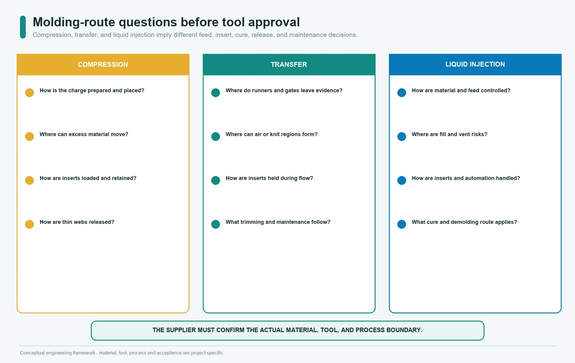
Compression molding, transfer molding, and liquid silicone injection molding are different production routes. None is automatically best for every keypad.
Compression molding questions
Ask how the charge is prepared and placed, how inserts are loaded, where excess material can move, how the mold is vented, and how the part is removed without distorting thin webs or tall keys. This route may fit some solid-silicone geometries, but the decision belongs to the actual material and tool design.
Transfer molding questions
Ask how material reaches each cavity, which runners or gates leave evidence on the part, how inserts are retained, and whether the flow path affects air, knit regions, flash, or delicate geometry. The correct gate location cannot be chosen from a generic diagram.
Liquid silicone injection questions
Ask about metering, mixing, cold-runner or feed concept, cavity fill, venting, insert handling, cure, demolding, automation, and process monitoring. A liquid injection route may support repeatable high-volume processing, but it can also impose a different tool, material, feed, and maintenance structure.
Solid or millable silicone processing must be distinguished from liquid injection systems because the material form and manufacturing route differ. That distinction does not establish a universal route for JASPER projects. The supplier must confirm the actual material and manufacturing boundary for the quoted keypad.
Treat Shrinkage as a Controlled Trial
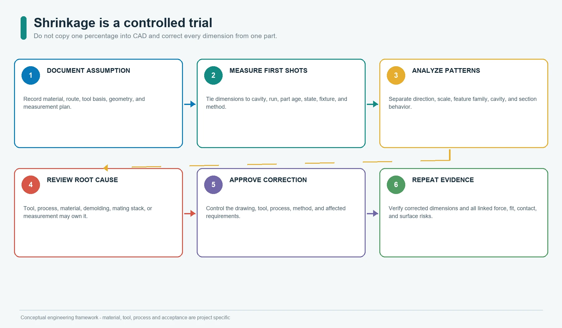
Silicone shrinkage is not one universal percentage that can be copied into the CAD model. It can be affected by material grade, cure system, processing route, tool temperature, cure history, post-cure, geometry, flow, restraint, inserts, measurement time, and measurement method.
A useful shrinkage plan separates three items:
- Initial tool assumption: the documented value used to create the first cavity.
- First-shot evidence: measured parts tied to material, tool, cavity, process, and age.
- Correction decision: the approved change to cavity dimensions or process after reviewing the complete pattern.
Do not correct every dimension independently after measuring one part. Look for direction, scale, section, cavity, and feature-family patterns. A global scale issue, local fill issue, demolding distortion, measurement-force issue, or assembly preload can produce similar numbers and require different actions.
Review the Mold Concept Before Steel Is Committed
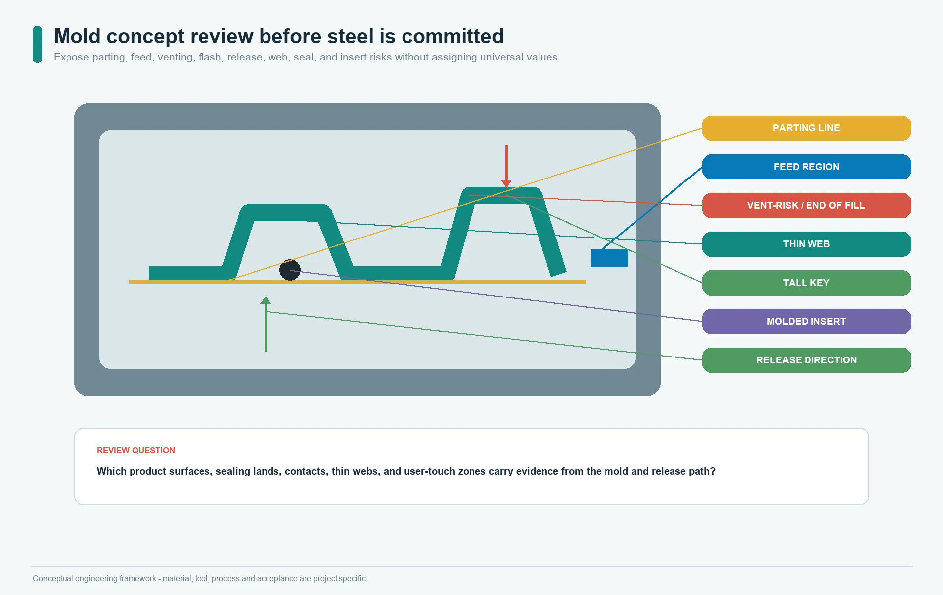
The tool review should make visible the features that can change part function or appearance.
Parting line
Identify where mold halves meet and where the witness line will be visible or functional. Keep it away from critical sealing lands, contact faces, optical surfaces, and user touch zones unless the risk is deliberately accepted.
Feed, gate, and charge location
Identify how material enters or is placed, where flow fronts meet, and which surface carries any remnant. The acceptable location depends on the process route and the feature, not on convenience alone.
Venting
Review where trapped air can collect, especially around thin webs, tall key walls, recesses, inserts, and end-of-fill regions. The actual vent design belongs to the toolmaker and material process; the OEM should still understand which product areas carry the risk.
Flash control
Define where flash is allowed, where it interferes with motion or assembly, how it is measured, and how trimming affects the surface. A generic statement such as no flash is not an inspection method.
Draft and release
Review how the part leaves the tool, which surfaces need release assistance, and whether the removal path stretches webs, damages coating lands, pulls inserts, or marks the visible face. Do not publish or contract a universal draft angle without the supplier’s geometry and process review.
Inserts and conductive elements
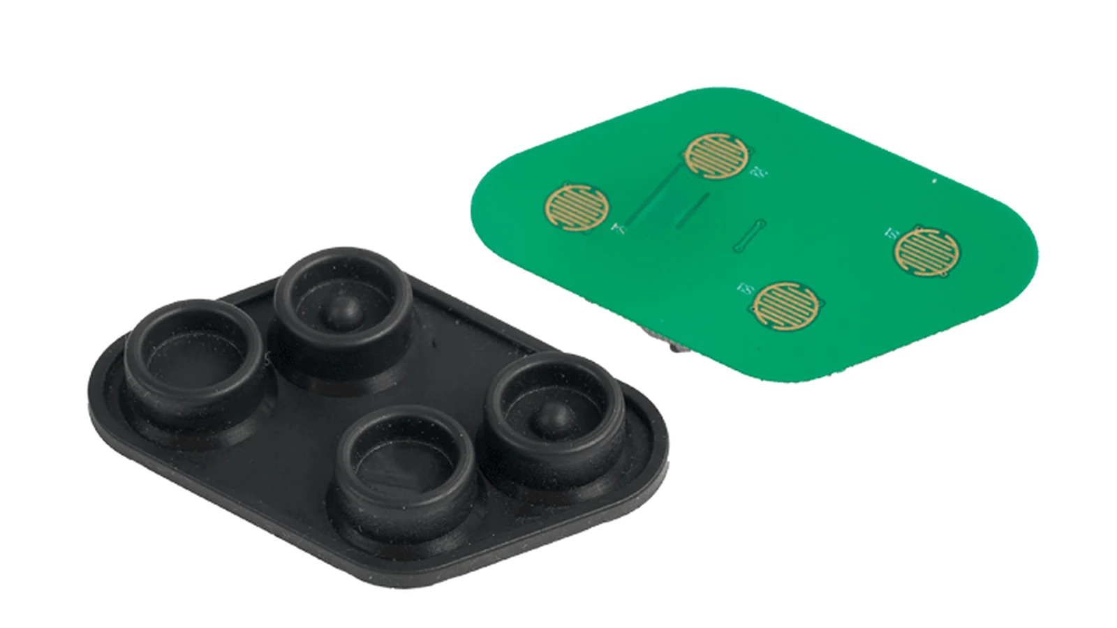
Define how carbon pills, metal pieces, light-control inserts, or other molded-in elements are identified, oriented, retained, and inspected. Their position should reference the same datums used for the PCB contact map.
Classify Dimensions by Function
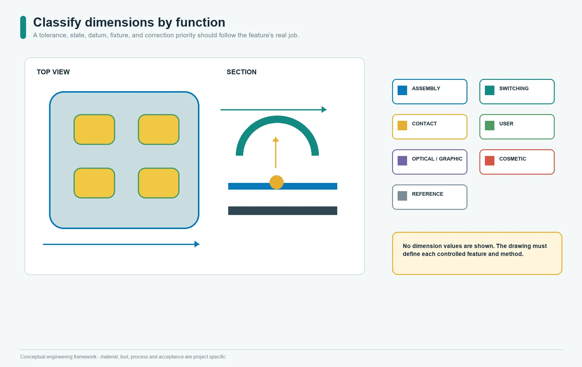
Not every dimension deserves the same tolerance, measurement method, or correction priority.
| Dimension class | Examples | Approval method |
|---|---|---|
| Assembly interface | outer profile, locating holes, bosses, seal lands | measured against mating housing and datum scheme |
| Switching geometry | web section, contact height, rest gap, key travel, hard-stop relationship | section measurement plus assembled force/electrical test |
| Contact registration | pill center, key center, PCB pad relationship | worst-case positional review and functional closure |
| User interface | key-top size, spacing, height, guide clearance | drawing measurement plus usability review |
| Optical and graphic | legend position, light window, coating boundary | artwork overlay, powered sample, visual criteria |
| Cosmetic | parting line, flash, texture, gate witness, trim area | defined viewing and defect criteria |
| Non-critical reference | dimensions that do not drive fit or function | reference or general-tolerance treatment |
ISO 3302-1 provides dimensional-tolerance classes for molded rubber products, while ASTM D3767 covers methods for measuring rubber dimensions. Neither source decides which keypad features are critical. The drawing must connect each functional feature to a datum, tolerance, method, and state.
Define Measurement State and Method
Rubber parts can change under contact force, handling, time, and conditioning. A dimensional report should state:
- free state or assembled state;
- time after molding or post-cure;
- conditioning or storage condition;
- fixture and support;
- measurement instrument and contact geometry;
- measurement force where relevant;
- feature locations and sample quantity;
- cavity, tool revision, material lot, and part revision;
- data resolution and treatment of outliers.
ISO 23529 covers preparation and conditioning concepts for rubber test pieces. Whole keypad requirements still need a project-specific method. When two teams measure a soft feature differently, the disagreement may be in the method rather than the mold.
Build Cavity and Revision Traceability Into the First Samples
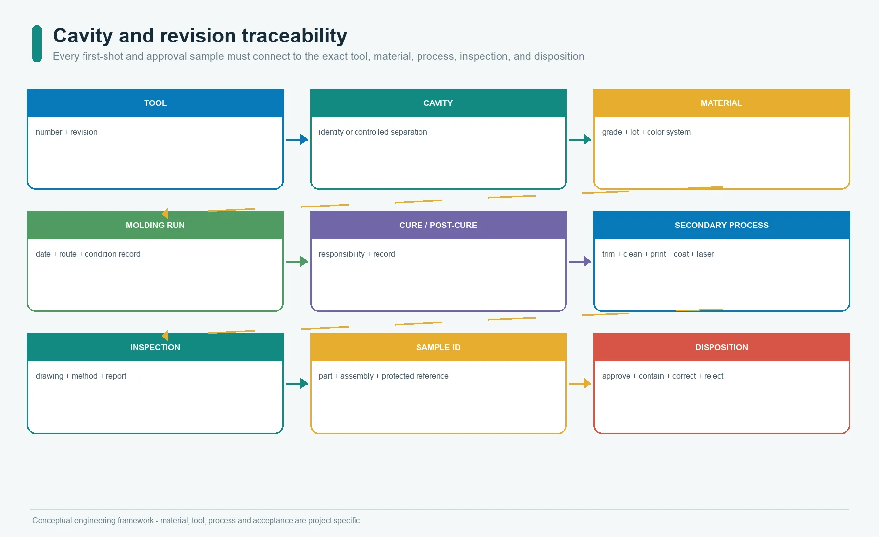
Every first-shot part should be traceable to:
- tool number;
- tool revision;
- cavity number or cavity family;
- material identity and lot;
- pigment or color system;
- insert or conductive-element lot where applicable;
- molding date and run;
- process route and approved condition record;
- cure and post-cure record if required;
- trimming, washing, coating, printing, laser, and assembly route;
- inspection report and sample disposition.
Cavity identity matters even when the finished product does not carry a visible cavity mark. The production record can use packaging separation, runner position, fixture position, or another controlled method approved by the parties.
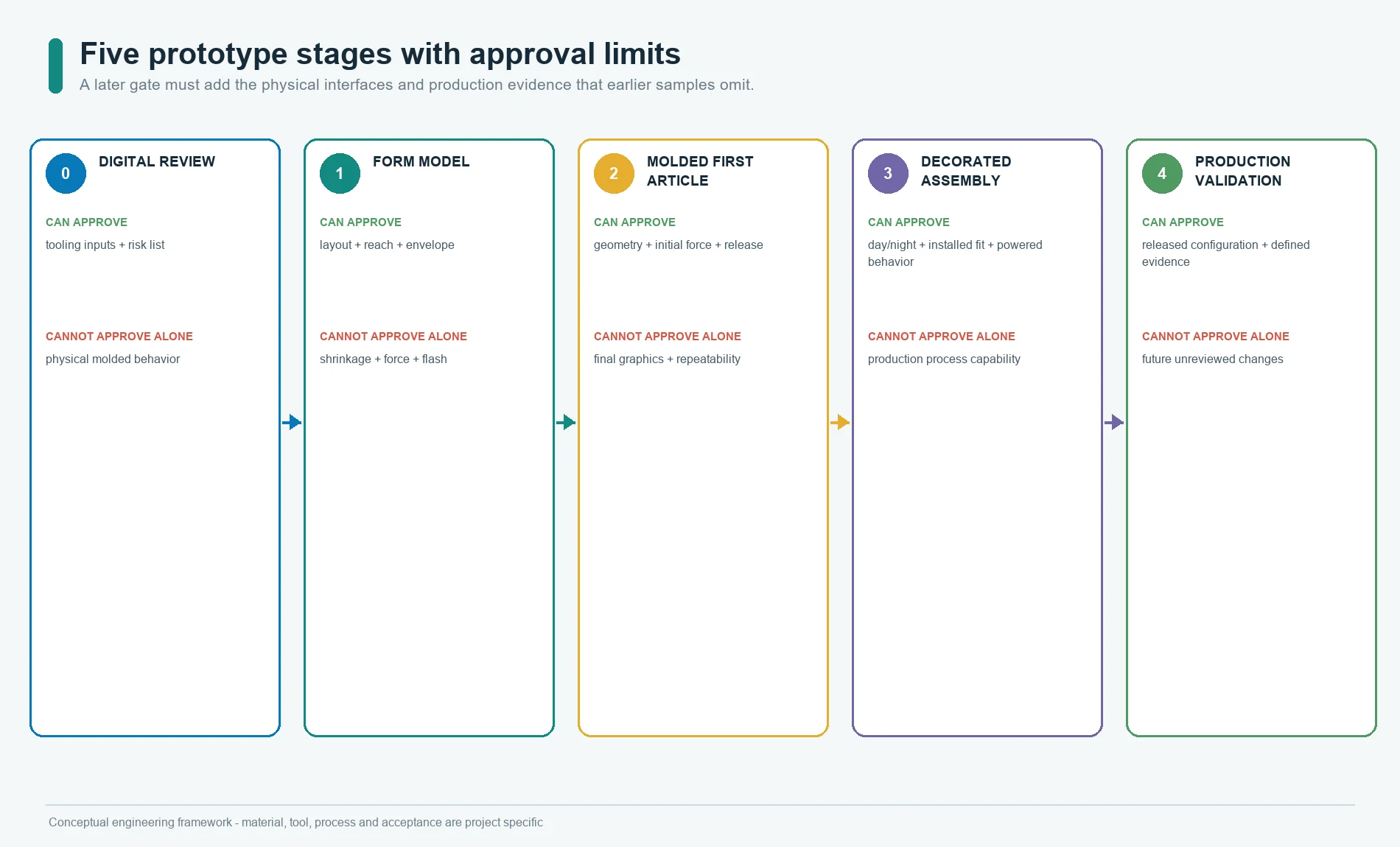
Use Prototype Stages With Explicit Approval Limits
The prototyping capability page describes prototypes as risk-reduction tools for fit, function, appearance, feel, lighting, and assembly. For silicone tooling, use more specific gates.
Stage 0: digital and risk review
Review CAD, sections, datums, stack, contact map, force target, molding route, surface route, and validation plan. This stage can approve the design basis for tooling. It cannot approve a physical part.
Stage 1: non-production form model
Use a model to review key layout, reach, spacing, enclosure envelope, connector access, labels, and service clearances. Mark every substitute material and process.
Stage 2: molded mechanical first article
Use intended or explicitly representative silicone, inserts, and tool geometry. Measure free-state dimensions, section geometry, force-displacement, contact location, return, flash, parting line, and demolding effects.
Stage 3: decorated and powered assembly
Add the approved circuit, housing, coating, legends, laser openings, LEDs, connector, spacer, gasket, and adhesive needed to evaluate the complete interface.
Stage 4: production-representative validation
Use the released tool revision, approved material and process, intended secondary operations, production inspection, packaging, and traceability. This stage supports production release only after the agreed validation and corrective actions are complete.
Record What Each Stage Can and Cannot Approve
| Stage | Can approve | Cannot approve by itself |
|---|---|---|
| Digital review | interfaces, risk list, tooling input | molded behavior |
| Form model | layout, reach, envelope, basic fit | shrinkage, force, flash, production surface |
| Molded first article | tool geometry, molded sections, initial force and release findings | final graphics, powered lighting, production repeatability |
| Decorated assembly | appearance, day/night presentation, installed fit, powered behavior | production process capability or lifecycle |
| Production-representative build | released configuration and defined validation evidence | untested future changes |
The sample label or report should state the stage. Do not let a mockup become a golden sample by accident.
Inspect the First Molded Samples in a Fixed Sequence
A disciplined order prevents a downstream test from hiding an upstream problem.
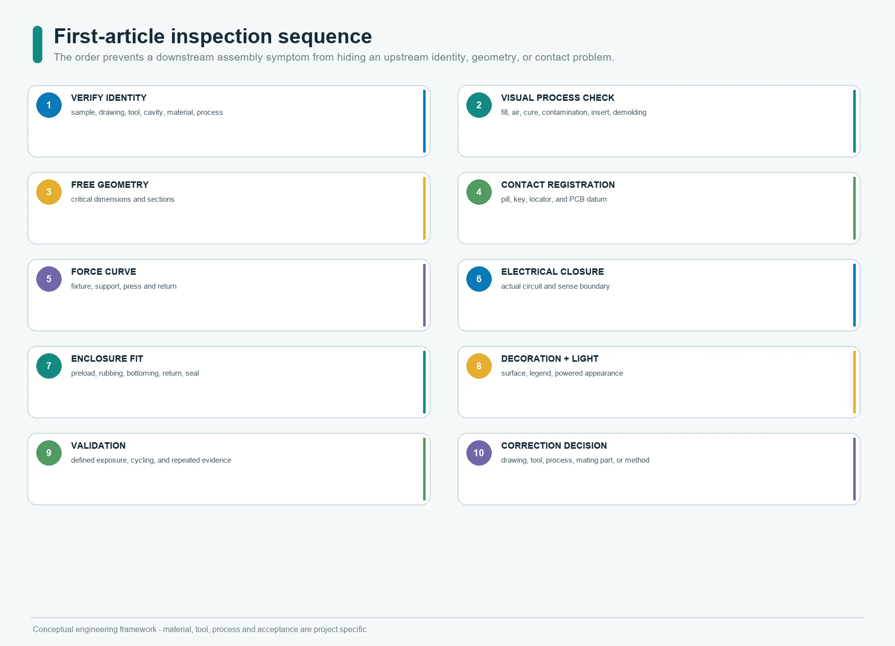
- Verify sample, drawing, tool, cavity, material, and process identity.
- Check for fill, air, cure, contamination, damage, insert, and demolding defects.
- Measure free-state critical geometry and section features.
- Confirm contact and locator position relative to datums.
- Measure force-displacement with the specified fixture and support.
- Add the actual circuit and measure electrical actuation at the defined sense point.
- Install the current enclosure and inspect preload, rubbing, bottoming, return, and seal compression.
- Add graphics, coating, laser, and lighting for the decorated approval.
- Run project validation and repeat measurements after defined exposure or cycling.
- Record every deviation and decide whether the drawing, tool, process, mating part, or test method must change.
Skipping identity and free-state checks can turn an assembly problem into an unnecessary tool correction.
Approve Key Feel With Curves, Not Adjectives
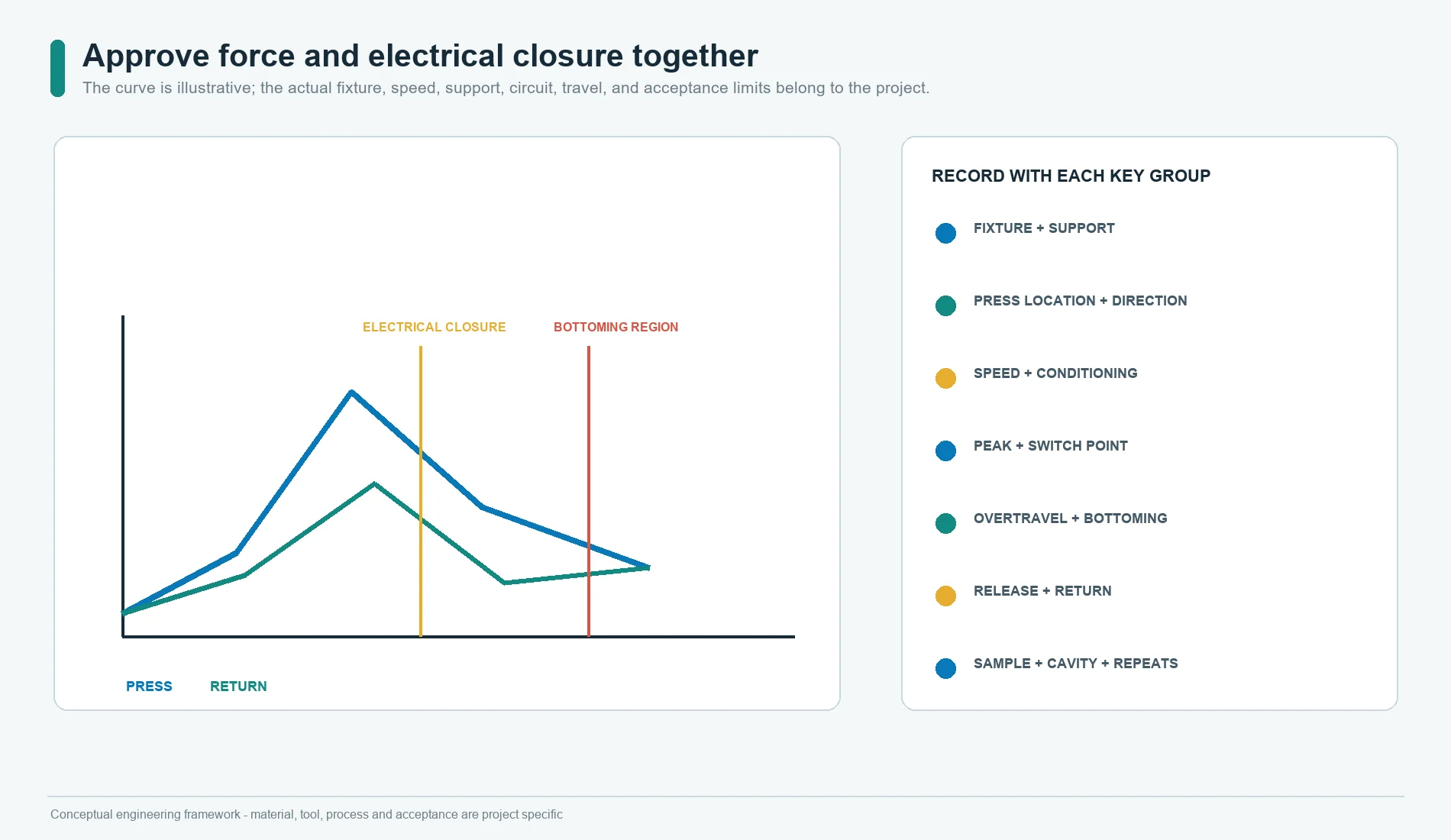
Soft, firm, snappy, and mushy are useful reactions, not complete specifications.
For each key group, record:
- key identity and role;
- fixture and PCB or support;
- actuator tip or finger surrogate;
- press location and direction;
- test speed;
- sample age and conditioning;
- peak force and its travel position;
- electrical switch point;
- overtravel and bottoming region;
- return path and release point;
- incomplete return, rubbing, or sticking;
- sample, cavity, and repeat count.
For keypad geometry and force-displacement design, see the silicone rubber keypad design guide. Record the measured curve with the sample and tool revision as part of the approval evidence.
Approve Electrical Closure in the Final Mechanical Stack
An electrical check should use the correct circuit carrier, support, contact location, and installed compression. Confirm:
- which nodes or pins are measured;
- open-state expectation;
- actuation point relative to force and travel;
- closed-state criterion at the specified test level;
- contact stability through overtravel;
- release behavior;
- intermittent events or bounce limits when required;
- matrix, pull-up, analog, or load-current boundary;
- whether the supplier tests the loose keypad, complete module, or both.
Detailed carbon-pill resistance, PCB contact geometry, and electrical acceptance belong to the separate carbon-contact article. This tooling guide focuses on making sure the molded part and final stack can reproduce the approved contact position.
Approve Graphics and Lighting as Separate Evidence
A molded sample does not approve a decorated keypad. A decorated unpowered sample does not approve backlighting.
The appearance record should identify:
- base silicone color;
- molded texture and gloss;
- printed ink, opaque coating, protective layer, or epoxy;
- laser artwork revision;
- legend position and edge condition;
- day-view color and contrast;
- powered LED and PCB revision;
- viewing angle and ambient-light condition;
- hot spots, light leakage, cross-talk, pinholes, and unlit appearance;
- approved color and visual reference method.
For abrasion, cleaning-agent exposure, coating adhesion, and laser-etched legend durability, see laser-etched silicone keypad legends and protective coatings. Include the agreed test conditions and acceptance criteria in the decorated-sample approval record.
Approve the Keypad Inside the Actual Enclosure
The installed assembly can change the result even when the loose keypad is correct.
Review:
- locating pins, holes, bosses, perimeter, and rotational control;
- PCB support and flex;
- guide clearance and side rubbing;
- hard-stop position;
- fastener sequence and torque ownership;
- gasket or seal compression;
- adhesive and spacer thickness;
- contact alignment;
- connector reach and strain relief;
- housing warpage and local clamp load;
- thermal movement and service access;
- free return after complete assembly.
For control equipment, the industrial-control application page provides useful questions about glove use, contamination, vibration, cable routing, visual hierarchy, and maintenance. It is application context, not proof that a silicone tool or assembly has passed those conditions.
Separate Seal Approval From Keypad Appearance
A molded perimeter lip or gasket feature is only one part of a sealing path. Production release should identify the complete tested assembly:
- keypad perimeter;
- enclosure land;
- corner radii;
- fasteners and clamp spacing;
- adhesive or gasket;
- cable, tail, or connector exit;
- display, vent, joint, and service opening;
- mating-part tolerances;
- assembly procedure;
- test method and sample configuration.
Do not assign an enclosure rating from a loose keypad sample. If the enclosure changes after keypad approval, the seal evidence may need to be repeated.
Include Packaging in the Approval Build
Soft molded parts can be distorted or contaminated after inspection. Review:
- stacking orientation;
- separators or trays;
- protection of coating, legends, windows, pills, and inserts;
- bend control for tails or attached circuits;
- dust and release-agent control;
- bag and label requirements;
- cavity, lot, and revision identification;
- storage and shipment constraints from the approved material/process plan.
Packaging is part of the delivered condition. A part that passes inspection and arrives deformed has not met the practical requirement.
Run a Closed Tool-Correction Loop
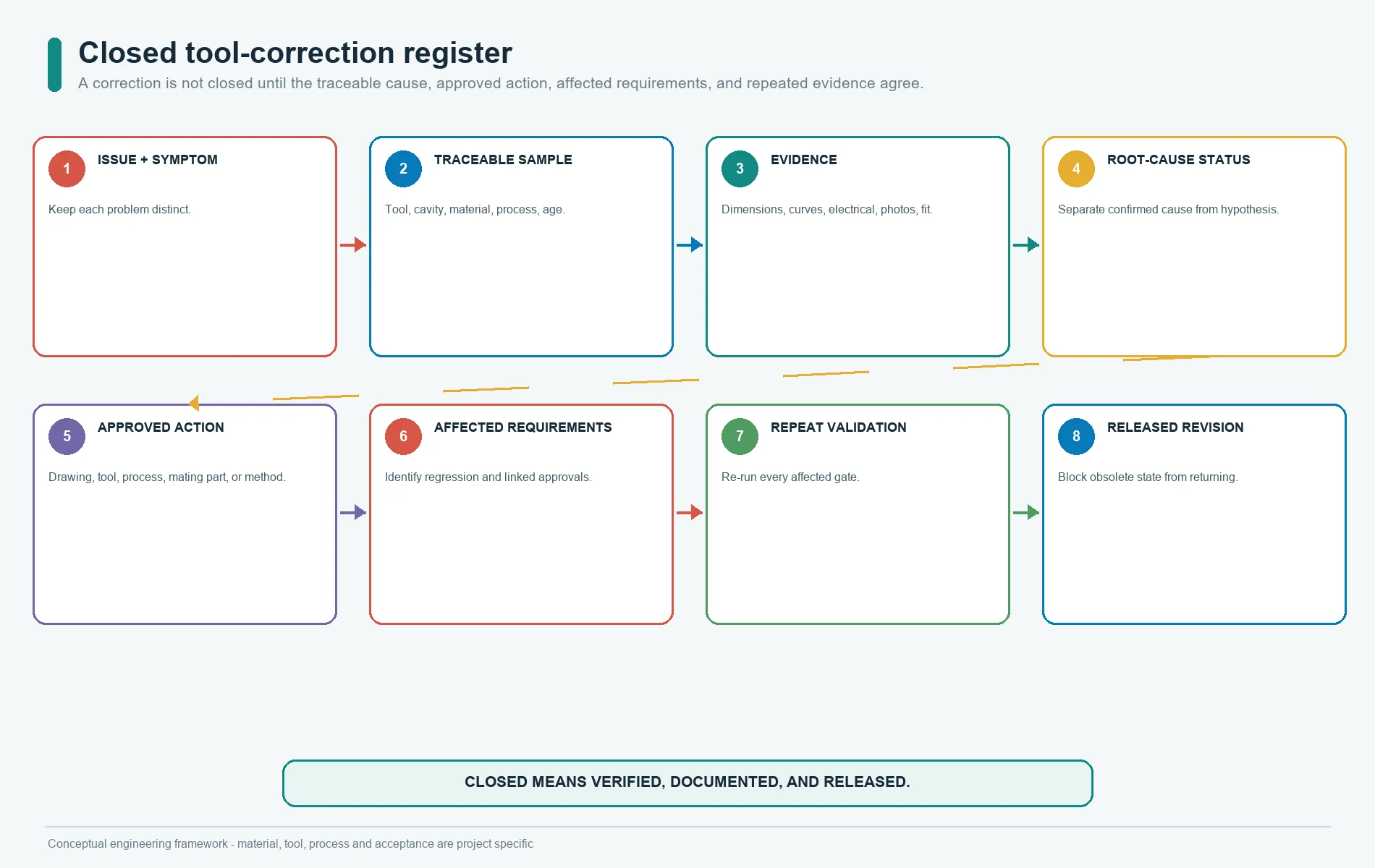
Every correction should answer five questions:
- What evidence shows the problem?
- Is the cause in the part definition, mold, process, material, mating assembly, or test method?
- Which dimensions or features will change?
- What other functions can that change disturb?
- Which measurements and validation must be repeated?
Use a correction register:
| Record field | Purpose |
|---|---|
| issue ID and symptom | keeps the problem distinct |
| sample, cavity, tool, material, and process | preserves traceability |
| evidence | dimensions, curves, photos, electrical records, assembly observations |
| root-cause status | separates confirmed cause from hypothesis |
| approved action | drawing, tool, process, mating-part, or method change |
| affected requirements | identifies regression risk |
| verification result | shows whether the correction worked |
| released revision | prevents return to an obsolete state |
Do not tune the process outside its approved window to hide a cavity or design problem. Do not cut the tool before the measurement method is trusted.
Use the Golden Sample Without Letting It Become the Specification
A protected golden sample is valuable for:
- tactile comparison;
- color and gloss reference;
- parting-line and flash interpretation;
- assembled fit;
- day/night appearance;
- packaging presentation.
It is weak at preserving:
- exact dimensions;
- force and release curves;
- electrical thresholds;
- color measurement;
- legend artwork;
- material identity;
- process settings;
- hidden geometry;
- change history.
Physical samples can age, relax, fade, become contaminated, or be handled differently. Store them with a sample ID, approval date, drawing revision, tool revision, cavity, material, process record, and replacement rule. The controlled data remains the acceptance authority.
Build a Production Release Package
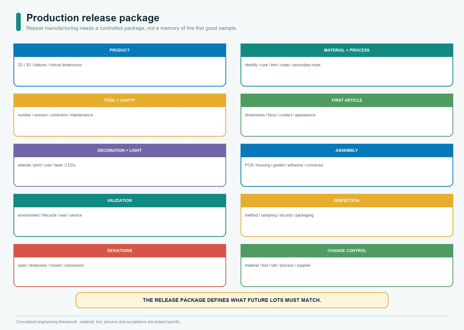
The release package should contain, as applicable:
- approved 2D drawing and 3D model;
- datum and critical-dimension list;
- material and color specification;
- tool number, tool revision, cavity plan, and approved correction history;
- molding, cure, post-cure, trimming, cleaning, and secondary-process responsibilities;
- conductive-element or insert specification;
- artwork, coating, print, laser, and lighting files;
- PCB, FPC, PET, connector, housing, adhesive, and gasket revisions;
- first-article dimensional report;
- force-displacement and return records;
- electrical function records;
- visual and powered-light acceptance;
- assembly and seal evidence;
- validation results;
- inspection plan and sampling agreement;
- packaging and labelling standard;
- golden sample register;
- deviation and concession status;
- change-notification rules.
The current JASPER testing and quality-control page provides a broad framework for visual, dimensional, electrical, tactile, adhesion, packaging, and lot records. It is membrane-interface focused and does not by itself confirm a silicone-mold inspection method or equipment set.
Define Tool Ownership, Storage, Maintenance, and Change Control
Commercial and engineering teams should settle these points before the purchase order:
- who owns the tool and which documents prove ownership;
- where the tool is stored and used;
- whether the tool can be transferred;
- which maintenance is routine and which is chargeable;
- who approves repair, polishing, welding, cavity work, coating, or replacement;
- how cavity condition and maintenance history are recorded;
- how long the tool and records are retained;
- what happens after inactivity;
- whether inserts, fixtures, gauges, and spare components are included;
- how material, tool, process, site, subcontractor, or inspection changes are notified;
- which changes require new first articles or validation.
The purchasing line one set of tooling is not enough to control these decisions.
Diagnose Approval Failures From Evidence
| Symptom | Possible evidence to check first | Do not assume |
|---|---|---|
| key is too stiff | web section, material identity, installed preload, fixture, curve | hardness alone caused it |
| key feels soft or vague | curve shape, web geometry, travel, PCB support, bottoming | the material is too soft |
| incomplete return | side rub, preload, web damage, coating, demolding, assembly | more lubrication is acceptable |
| intermittent closure | contact position, support, travel, circuit, contamination | the mold needs more overtravel |
| uneven dimensions | cavity pattern, measurement method, part age, demolding, process | one shrinkage percentage fixes all features |
| excessive flash | parting condition, clamp, material, process, trim method | cosmetic acceptance covers functional flash |
| visible sink or fill defect | section, feed, air, material, cure, process record | it is only cosmetic |
| light hot spot or leakage | LED/PCB revision, wall/coating geometry, assembly gap | changing the tool is the only solution |
| seal failure | complete load path, land, fasteners, exits, tolerances, assembly | the keypad perimeter alone is defective |
| lot-to-lot feel shift | material, process, cavity, part age, curve method, assembly | the golden sample is sufficient data |
Correct the cause that the evidence supports, then repeat the affected approvals and regression checks.
Stop Tooling or Production Release When These Inputs Are Missing
Stop tooling release when:
- the PCB, housing, or contact map is not on a controlled revision;
- key force is described only by adjectives;
- material or molding route responsibility is unknown;
- critical datums and dimensions are not classified;
- the parting line, feed, vent, flash, demolding, or insert risks have not been reviewed;
- shrinkage is treated as a copied universal value;
- prototype stages and approval limits are undefined;
- no first-article measurement plan exists;
- coating, laser, or lighting artwork is changing;
- the delivered assembly boundary is unclear.
Stop production release when:
- samples cannot be tied to tool, cavity, material, process, and revision;
- corrective actions are still open;
- the assembled keypad differs from the test configuration;
- force, return, electrical, visual, lighting, fit, seal, or packaging evidence is incomplete;
- a temporary deviation has become the undocumented normal process;
- the golden sample conflicts with the controlled drawing or test data;
- tool ownership, maintenance, or change notification remains disputed.
What Should an OEM Send for a Silicone Keypad Prototype Review?
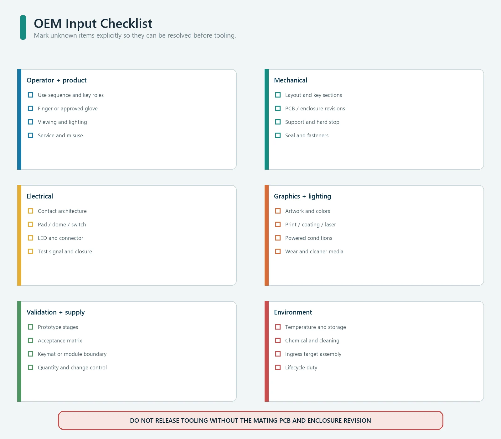
Send:
- 2D drawing and 3D model with revision;
- mating PCB, contact pattern, and electrical interface;
- enclosure CAD, section, hard stops, supports, fasteners, and seal lands;
- key map, user roles, glove or cleaning conditions, and visual hierarchy;
- target force-displacement and travel behavior;
- contact, circuit, lighting, legend, color, texture, and coating requirements;
- material, compliance, environment, lifecycle, and validation requirements;
- delivered boundary: loose keymat or assembled module;
- prototype quantity, annual quantity, launch timing, and documentation needs;
- existing failure evidence or approved reference sample.
Use the RFQ form to send the controlled drawing, mating-part revisions, target approval gates, and expected production scope. Ask for an engineering review of the mold and sample plan before treating price and lead time as fixed.
Frequently Asked Questions
Can a 3D-printed keypad approve silicone production tooling?
No. It can help approve layout, reach, key spacing, enclosure clearance, and some ergonomic decisions. It cannot reproduce the selected silicone material, molded web behavior, shrinkage, flash, parting line, demolding, insert loading, cure, force curve, or production surface.
Should the first molded sample become the golden sample?
Only after the drawing, tool revision, cavity, material, process, measurements, deviations, and approval status are known. A first sample with open corrections should remain an engineering sample.
Can one shrinkage value be used for the entire keypad?
Not safely as a universal rule. The initial tool may use a documented assumption, but first-shot measurements should check direction, section, geometry, cavity, cure, post-cure, and measurement method before any correction is approved.
Does meeting an ISO 3302-1 tolerance class approve the keypad?
No. A tolerance class can support dimensional requirements for molded rubber products. The project must still identify critical dimensions, datums, measurement state, key-force behavior, electrical function, graphics, lighting, assembly, seal, and validation criteria.
Is Shore A hardness enough to specify key feel?
No. Durometer hardness is a material test. Installed key feel also depends on web geometry, key-top shape, travel, support, preload, hard stops, contact closure, test speed, and assembly.
When should the OEM approve tooling?
Approve tooling input only after the product, mating parts, material/process boundary, critical geometry, mold concept, prototype plan, and acceptance methods are controlled. Approve production only after the released tool and production-representative parts pass the required evidence gates.
Who should own the silicone keypad mold?
The commercial agreement decides ownership. It should also cover tool identification, storage, permitted use, maintenance, repair approval, transfer, record retention, inactivity, replacement, and change notification.
Does an approved loose keypad approve the complete assembly?
No. PCB support, contact position, housing guides, fasteners, preload, adhesive, gasket, connector, lighting, and enclosure tolerances can change force, return, electrical closure, appearance, and sealing.
Ready to Start Your Project?
Tell us about your membrane switch, keypad, or graphic overlay requirements. Our engineering team will review your specifications and provide a detailed quote.