
ELECTROTHERAPY ELECTRODE MANUFACTURING
Custom TENS / EMS Electrode Pad Circuits
JASPER is a TENS electrode pad manufacturer for OEM teams developing customer-specific stimulation electrode circuits, converted pad layers and connection interfaces under a released technical definition.
JASPER controls the quoted printing, conversion and assembly operations. The device owner defines stimulation use, current-delivery requirements, skin-contact materials, treatment protocol, reuse policy, clinical performance and regulatory release.
- Custom pad geometry
- Lead, snap or printed-tail interface
- Drawing-controlled conversion
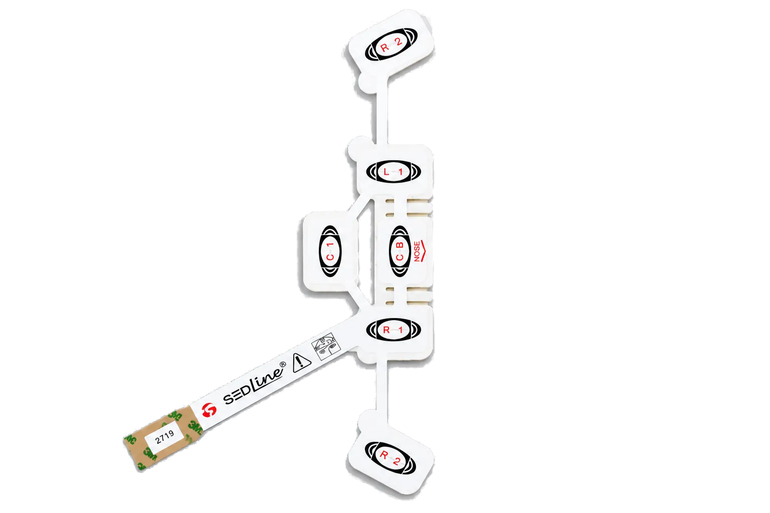
PRODUCT BROCHURE
Medical Electrode Product Brochure
Review physiotherapy and muscle-electrode examples plus conductive adhesive, medical foil, carbon film, and electrode clip options. The brochure helps compare standard constructions; send the pad drawing, intended use, connector requirement, and annual volume for an engineered quotation.
STIMULATION PROGRAM BOUNDARY
Design the current path, pad stack and connection as one system
TENS, EMS, NMES and other electrotherapy electrode programs may share manufacturing operations, but they do not share universal electrical or patient-contact limits. The supplier drawing must expose the decisions that affect current distribution and use.
JASPER can manufacture to
- Project-defined conductive pad areas and printed interconnect patterns
- Flexible substrates, dielectric coverage, die cutting and lamination
- Specified hydrogel, adhesive, liner, foam or spacer integration within scope
- Printed tail, snap, lead-wire or connector-interface conversion
- Prototype samples and repeat builds against approved artwork and inspection criteria
The device team defines and validates
- Stimulation modality, waveform, current density and treatment parameters
- Electrode placement, active area and return-path design
- Skin-contact, biocompatibility and sensitization requirements
- Single-use or reuse definition, cleaning, wear and storage protocol
- Clinical safety, labeling, risk management and finished-device approval
DESIGN ROUTES
Select the stimulation-electrode connection route early
Pad outline is only one variable. The electrical connection and use sequence usually determine the tail design, local reinforcement, liner arrangement, converted stack and inspection method.
01 / PRINTED TAIL
Integrated flexible connection
02 / LEAD OR SNAP
Discrete connection interface
03 / MULTI-PAD ARRAY
Distributed stimulation pattern
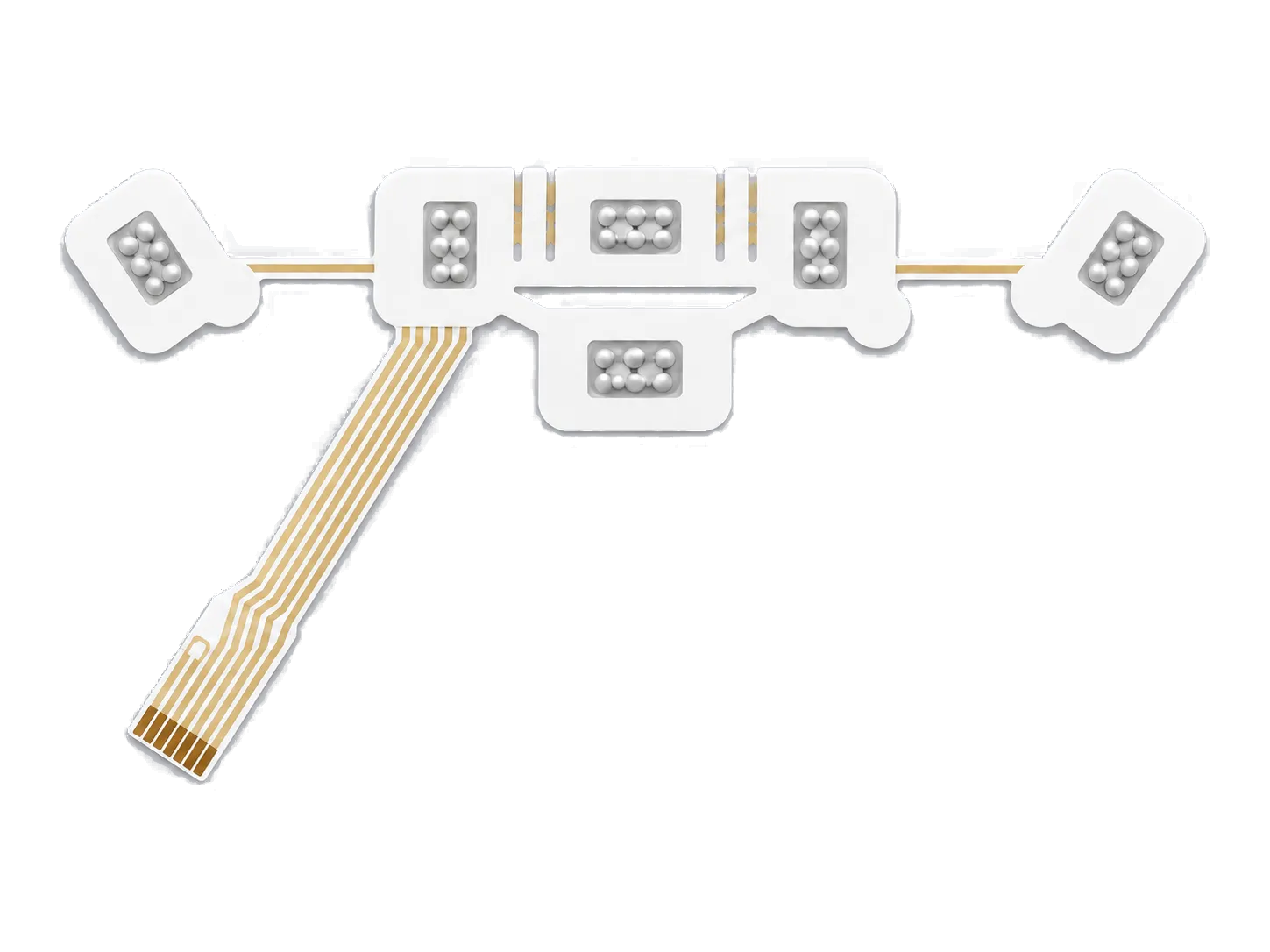
PAD-TO-CONNECTION CONTROL
Keep manufacturing limits separate from therapy performance
JASPER can inspect printed geometry and quoted electrical characteristics. Therapeutic effect, current density, patient comfort and safe operating limits belong to the validated device system.
ACTIVE AREA
Dimension the current-delivery surface
CONNECTION
Control the local load path
LINER SEQUENCE
Design for handling and placement
ACCEPTANCE
Define electrical and mechanical checks
CONTROLLED PROJECT FLOW
Move from stimulation concept to a controlled electrode build
- 01
Define use inputs
Document the pad map, connection route, material roles and customer-owned stimulation and patient-contact requirements.
- 02
Resolve interfaces
Review printable geometry, gel or adhesive coverage, attachment details, liner sequence and conversion tolerances.
- 03
Prototype the stack
Build one controlled revision so the customer can test electrical behavior, placement, mechanics and device integration.
- 04
Approve evidence
Close test results, material records, deviations, drawing changes and acceptance limits before production release.
- 05
Control repeat builds
Use released artwork, BOM, process definition, inspection plan and approved sample for repeat manufacture.
RFQ INPUTS
What to send a TENS or EMS electrode pad manufacturer
A useful RFQ links the physical pad construction to the device's electrical and mechanical interfaces while keeping customer-owned therapy claims clearly identified.
Send the Current Revision- Dimensioned pad outline, active areas and channel map
- Printed trace and dielectric artwork
- Target carrier, ink, gel, adhesive and liner specifications
- Snap, lead-wire, printed-tail or connector details
- Liner split, placement and removal sequence
- Customer-approved electrical and mechanical test limits
- Packaging, storage and material-document requirements
- Prototype quantity, annual forecast and device milestone
BUYER QUESTIONS
TENS and EMS electrode manufacturing FAQ
The exact stimulation-electrode deliverable is controlled by the quote, drawing and customer validation plan, not by generic claims attached to a sample image.
Can JASPER manufacture both TENS and EMS electrode circuits?
JASPER can review custom printed and converted electrode constructions for TENS, EMS and related stimulation programs when the customer supplies the required geometry, materials, connection interface and acceptance criteria.
Can the electrode use a lead wire, snap or printed tail?
Those connection routes can be reviewed within the quoted assembly scope. The customer must define the mating interface, electrical assignment, mechanical load, reinforcement and device-level validation requirements.
Does JASPER choose the hydrogel or skin adhesive?
JASPER can work with nominated materials or support a documented sourcing review, but the medical-device customer must approve patient-contact suitability and evidence for the intended use.
Can one converted part contain several stimulation pads?
Yes, a customer-controlled design may use multiple contact areas in one flexible array. Spacing, channel function, application sequence and current-distribution validation remain device-program inputs.
Are the electrodes reusable or self-adhesive?
Those are not universal attributes. Reuse, cleaning, adhesion and wear claims depend on the exact material stack, packaging, instructions and validated finished device.
What tests can JASPER perform during production?
Project-defined dimensional, continuity, resistance, attachment or cosmetic checks may be quoted when methods, fixtures, limits, sampling and disposition rules are supplied and approved.
Who is responsible for safe stimulation levels and clinical performance?
The device owner is responsible for waveform, current density, treatment protocol, electrical safety, patient-contact requirements, clinical validation, labeling and regulatory release.
START WITH EVIDENCE
Have a stimulation-electrode drawing or sample to review?
Send the pad map, material stack, connection method, liner sequence, customer-owned test requirements and volume. JASPER will identify the print, conversion and assembly decisions needed for a defensible quote.