
OEM MEMBRANE SWITCH FAMILY
Shielded Membrane Switches
EMI/RFI shielding and ESD design options for OEM equipment.
Send your panel drawing, display-window details, circuit pinout and available chassis connection. JASPER reviews shielding and keypad construction together for your equipment.
OEMs that ship with our switches inside





01 / ENGINEERING REVIEW
What is a shielded membrane switch?
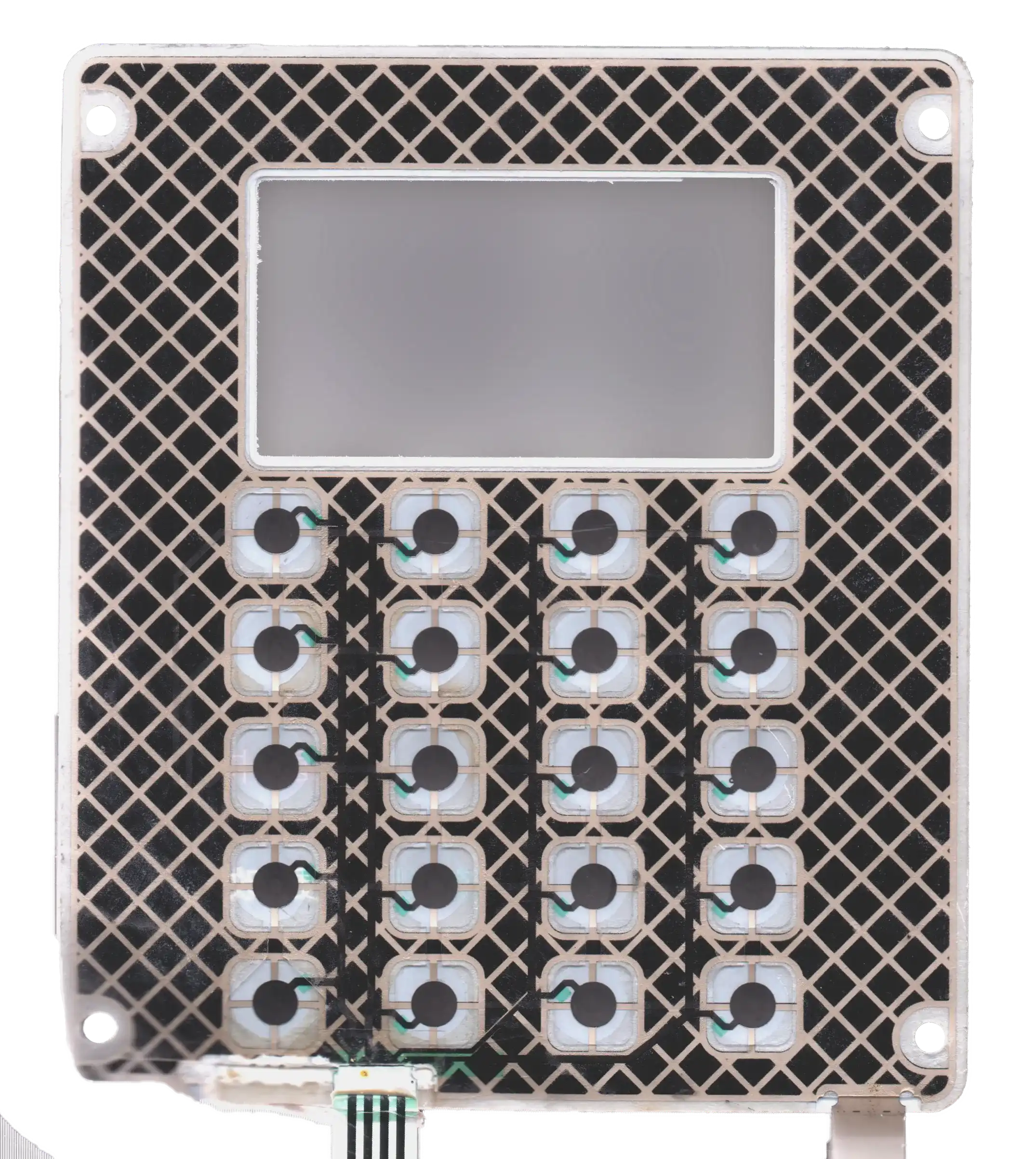
A shielded membrane switch combines a layered keypad circuit with a conductive shield and a specified termination path. The shield can be printed or laminated into the construction; its position and connection are selected around the circuitry and the equipment’s protection requirements.
Shielding is an additional design feature, not a replacement for the switch mechanism. A membrane switch can still have tactile or non-tactile keys, display windows and backlighting. Its shielding must also work with the enclosure, wiring and controller.
02 / ENGINEERING REVIEW
Start with the electrical problem, not just a shielding material
Shielded membrane keypads need a defined protection objective. An ESD event at an operator-accessible surface is a different problem from RF coupling into a cable or interference from nearby power electronics. Describe the environment and observed behavior before selecting the shield.
| Requirement | What the design review needs | What not to assume |
|---|---|---|
| ESD protection | Accessible surfaces, discharge locations, enclosure construction and the intended discharge path | A conductive layer alone establishes a finished equipment ESD rating |
| EMI/RFI control | Suspected source, frequency information when known, cable arrangement and sensitive circuits | Every interference problem enters through the keypad face |
| Display-area shielding | Clear aperture, optical requirements, shield continuity and edge connection | An opening cut through an opaque shield remains electrically equivalent to the covered area |
| Reliable field assembly | Bonding surface, mounting hardware, tail routing and inspection access | A correct loose sample will perform identically after an undocumented installation change |
False key inputs or resets are symptoms, not a diagnosis. A useful review includes the controller and cable conditions as well as the membrane. Specify the enclosure, available grounding connection and display openings together in the membrane switch design review.
03 / ENGINEERING REVIEW
Shield construction options to review
Printed shields, foil laminates, metallized films and window-compatible materials offer different integration choices. Select a construction by its coverage, electrical connection and mechanical fit, then validate the assembled result. These are design-review options; the released drawing defines the supplied material and process.
| Construction | Useful design role | Confirm before sampling |
|---|---|---|
| Printed conductive layer | A patterned grid or coating integrated with the film construction | Conductive material, coverage, isolation, connection area and the approved print pattern |
| Metal-foil laminate | A conductive sheet shaped around the keypad and its openings | Foil, insulating layers, edge treatment, bonding method and total stack thickness |
| Metallized polymer film | A film-based conductive layer within the assembly | Conductive face, handling limits, continuity through the proposed shape and termination method |
| Window-compatible mesh or coating | A conductive solution where the display must remain visible | Optical appearance, clear aperture, edge termination, handling and assembly validation |
Compare circuit substrates and conductive materials alongside shield coverage, window requirements and termination. Neither a material name nor a photograph establishes a universal shielding-effectiveness value.
04 / ENGINEERING REVIEW
Define how the shield connects to the equipment
A shield termination needs an intentional electrical and mechanical interface. Name the connection point. Identify the contact area and assembly method on the drawing. Do not leave the installer to decide whether a loose tab touches a painted bracket or an unspecified ground pin.
A dedicated tab or bonding tail
A separate tab can provide an identifiable connection to a specified chassis or backing structure. The design review needs the mounting location, contact-surface condition and available assembly space. Include tail support and inspection access, not just the tab’s outline.
A connection through the circuit connector
A connector-based termination can be considered when the mating electronics provide the intended connection. Mark the shield pin separately in the pinout and confirm its destination. Do not assume that keypad common, controller signal ground, chassis and protective earth are interchangeable.
Perimeter or wrap-around bonding
An edge connection may be appropriate when the enclosure design needs continuity around the assembly. Coverage, seams and contact geometry become part of the design. The correct approach depends on the system; a convenient single connection is not automatically equivalent to perimeter bonding.
Conductive adhesive is an electrical material as well as a bonding material. During adhesive material selection, specify both the bonding surface and the required electrical connection. Use the actual material data and mounting surface, rather than treating any foil tape as interchangeable.
05 / ENGINEERING REVIEW
Give display windows and tail exits their own review
A display window creates both an optical requirement and an opening to evaluate in the shielding plan. Define the visible area, bezel overlap, window finish and any conductive window layer together. Transparency is not conductivity. The optical and electrical requirements need separate checks.
For a shielded keypad with an LCD window, the review should answer four questions:
- Does the display aperture need conductive coverage, or is the enclosure design handling it elsewhere?
- How does any window shield join the surrounding shielding path?
- Will the proposed mesh, coating or layered window meet the actual viewing conditions?
- Can the connection remain intact after bonding, cleaning and assembly handling?
The tail exit also needs space, support and separation from other connections. A shield tail must not create an unintended contact with functional traces. Review the connector and tail interface against the real mating part, contact orientation and installation path.
06 / ENGINEERING REVIEW
Build the shield into the complete keypad specification
Shielded membrane switch design must preserve the operating interface as well as the conductive path. Additional layers and connection features can affect local clearances, assembly access and the relationship between the face panel and its support.
| Assembly decision | Specify together with the shield |
|---|---|
| Graphic overlay | Material, graphics, window locations, key identification and cleaning exposure |
| Tactile or non-tactile operation | Contact construction, support, local clearance and the approved feel target |
| Printed PET, FPC or PCB circuit | Circuit geometry, component locations, isolation and the controller pinout |
| LED or other backlighting | Light paths, component clearance, masks and electrical connections |
| Adhesive and environmental sealing | Bonding surface, sealed boundary, openings and shield termination access |
| Enclosure mounting | Support points, contact surfaces, fasteners, cable routing and assembly sequence |
Projects that need component integration can be reviewed alongside PCB and FPC membrane switches. For illuminated controls, bring the backlighting requirements into the same review. Shielding and waterproof construction address different requirements; neither establishes the other.
07 / ENGINEERING REVIEW
Applications that benefit from a defined shielding plan
The equipment environment determines whether shielding is needed and what must be verified. These examples are design situations, not claims of completed customer projects.
Instrumentation and weighing controls
An instrument interface may combine a keypad, display and sensitive electronics in a compact housing. Document the measurement electronics, connector routes and enclosure connection so the keypad shield can be reviewed as part of that system.
Industrial control panels
Industrial controls may operate near motor drives, switched loads and long cables. Identify the actual noise sources and installation arrangement; adding a shield to the front face is not a substitute for reviewing other coupling paths.
Medical and laboratory equipment
Medical equipment interfaces combine operator access, cleaning requirements and defined system performance criteria. Coordinate shield termination with the equipment’s electrical design. The device team determines applicable safety and EMC requirements.
Operator terminals and public-use equipment
Kiosk and vending interfaces can combine a large display opening, keypad and several cable connections. Review accessible surfaces, service assembly and any intended wireless functions before finalizing the conductive coverage.
08 / ENGINEERING REVIEW
Validate the assembly—not only the material
An acceptance plan should separate checks on the supplied keypad from tests on the operating equipment. A continuity result confirms a particular electrical path; it does not measure the complete system’s immunity.
| Verification stage | What to define in the project record |
|---|---|
| Drawing review | Shield coverage, isolation, termination, contact surfaces and the approved configuration |
| Keypad inspection | Functional circuits, shield-path continuity, separation from signal nets, appearance and connection locations |
| Installed sample review | Mounting, bonding contact, tail routing, display appearance and normal keypad operation |
| System qualification | Relevant disturbance, test method, equipment setup, operating modes, monitoring and acceptance criteria |
IEC 61000-4-2:2025 addresses electrostatic-discharge immunity testing. IEC 61000-4-3:2020 addresses radiated RF electromagnetic-field immunity. Applicability and test levels must follow the equipment requirements; citing a method is not evidence that a product has passed it.
Agree the required evidence during the testing and quality-plan review. Changes to a display opening, shield connection, cable route or enclosure may require the team to reconsider the previous validation.
09 / ENGINEERING REVIEW
Send the details that make a shielded-keypad quote useful
A useful RFQ connects the mechanical drawing to the electrical problem. Send the following information with your request:
- Panel dimensions, artwork, key layout and quantity.
- Display-window size, bezel arrangement and viewing requirements.
- Functional circuit and pinout, mating connector and cable arrangement.
- The available chassis or grounding connection, including its surface and location.
- Known interference sources, symptoms or test requirements.
- Tactile feel, lighting and environmental requirements.
- Thickness limits, support points and the installation sequence.
- Sample acceptance criteria and required project documents.
An existing sample or clear photographs can help explain the assembly, but a front view alone cannot define the shield. JASPER can review the proposed keypad construction against the supplied equipment requirements and identify the information needed before quotation and sampling.
YOUR QUESTIONS, ANSWERED
Shielded membrane switch FAQ
What is the difference between a shielded and a waterproof membrane switch?
A shielded membrane switch includes a conductive shielding arrangement; a waterproof design addresses ingress through the assembled interface. These requirements can coexist, but they need separate design and validation checks. Shield terminations and display openings must be coordinated with the sealed boundary.
Does adding a shield guarantee equipment EMC compliance?
No. The keypad is only one part of the equipment’s EMC design. The enclosure, cables, controller, openings and bonding arrangement all matter. Define the applicable tests and acceptance criteria for the assembled equipment, then validate the released configuration.
Which shielding material is best for a membrane keypad?
There is no material that is best for every keypad. Printed conductive layers, foil laminates, metallized films and window-compatible materials address different integration needs. Compare coverage, connection, isolation, thickness and viewing requirements before selecting a construction for validation.
Can a shielded membrane switch include a clear LCD window?
Yes, but the window needs its own electrical and optical review. A mesh or transparent conductive coating may be considered where conductive coverage is required. Specify the clear aperture, edge connection and display appearance; an ordinary clear film is not automatically a shield.
Can the shield use the same connector as the keypad circuit?
A connector-based termination can be considered if the mating system provides the intended connection. Identify the shield pin and its destination explicitly. The keypad common or controller ground must not be assumed to provide the required chassis-bonding or protective-earth function.
Can shielding be combined with tactile keys, FPC circuits or backlighting?
These features can be reviewed within a shielded assembly. They must be considered together because shielding can affect layer clearances, electrical isolation, window coverage and connection routing. The approved construction defines the combination supplied, rather than a generic feature list.
Which shielding-effectiveness and ESD requirements belong in an RFQ?
Provide the equipment requirement and test conditions, not an isolated number. For shielding effectiveness, identify the frequency range and measurement context. For ESD, identify the required method, test level, discharge locations and acceptance criteria. A material value alone does not specify the finished keypad or equipment result.
Can an existing membrane switch be redesigned with shielding?
An existing design can be assessed for a shielding revision. The review needs the circuit, window geometry, enclosure connection and available stack space. A new conductive layer or termination may change assembly and validation requirements, so it should not be treated as an automatic drop-in revision.
A CLEARER BRIEF. A BETTER DESIGN REVIEW.