
ECG / EKG ELECTRODE MANUFACTURING
Custom ECG / EKG Electrode Patch Circuits
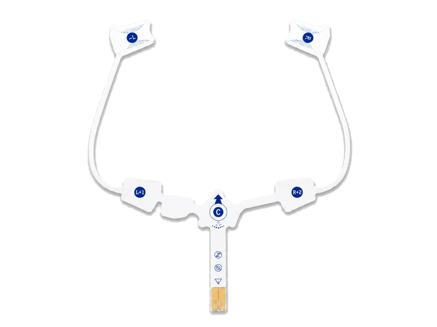
JASPER is an ECG electrode manufacturer for OEM monitoring programs that need a custom printed electrode map, flexible routing, converted layers and a controlled electronics interface rather than a catalog patch.
JASPER builds the customer-defined printed and converted construction. The device owner controls electrode placement, patient-contact requirements, signal performance, wear protocol, clinical validation and regulatory release.
- Single- or multi-site layouts
- Flexible printed trace routing
- Prototype to repeat builds
PRODUCT BROCHURE
Medical Electrode Product Brochure
Review standard ECG electrode examples together with disposable neutral and physiotherapy electrode formats, conductive adhesive, medical foil, carbon film, and clip options. The brochure is a product overview, not an engineering RFQ; send the drawing and intended use for a project-specific quotation.
MONITORING PROGRAM BOUNDARY
Translate the electrode map into a manufacturable flexible circuit
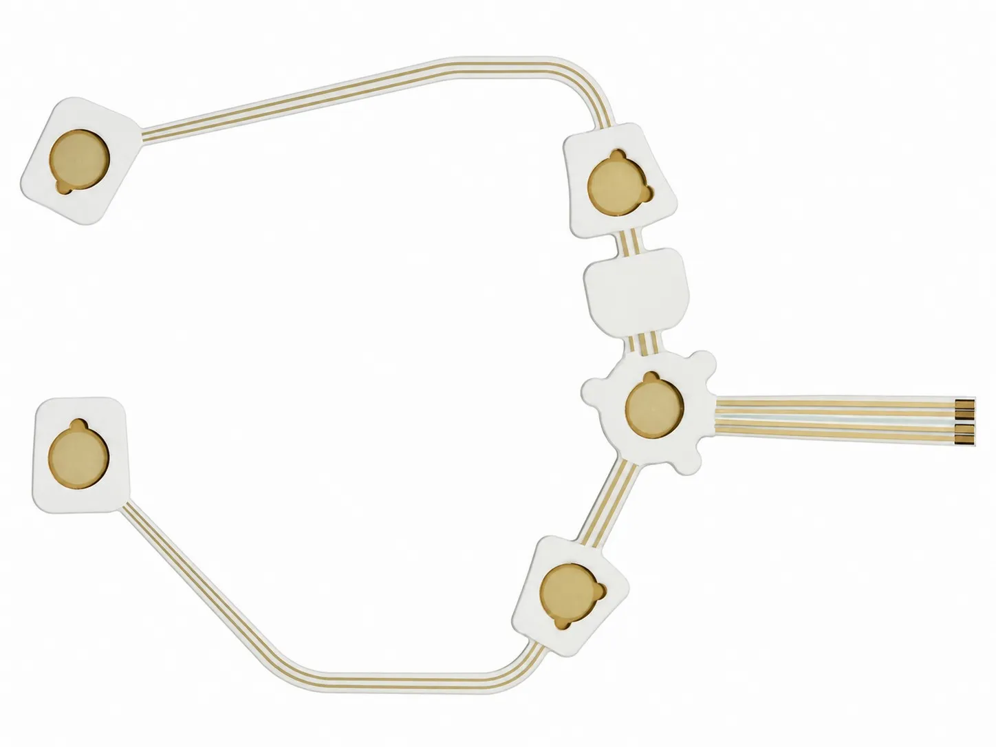
An ECG patch is not defined by its outer shape alone. Electrode locations, trace routing, contact windows, mechanical transitions and the connection to the recorder must be reviewed as one drawing-controlled assembly.
JASPER can manufacture to
- Screen-printed conductive traces and project-defined electrode areas
- Flexible carrier conversion, dielectric windows and layer registration
- Single-lead or multi-lead geometries from released customer artwork
- Tail contacts, reinforcement, connector interface or specified lead attachment
- Sample builds, drawing revisions and repeat production to an approved definition
The device team defines and validates
- Monitoring architecture, channel assignment and anatomical placement
- Skin-contact material, adhesive, gel and biocompatibility requirements
- Signal quality, impedance limits, motion-artifact targets and acceptance methods
- Wear duration, packaging, shelf-life, labeling and disposal requirements
- Clinical performance, risk management, regulatory submissions and final release
DESIGN ROUTES
Choose the ECG patch architecture before optimizing the stack
A useful supplier review begins with the electrical map and mechanical use case. These common routes lead to different trace, tail, placement and conversion decisions even when the printed materials appear similar.
01 / COMPACT MONITORING
Single-lead patch circuit
02 / DISTRIBUTED CONTACTS
Multi-lead electrode array
03 / REMOTE ELECTRONICS
Patch with flexible tail or lead interface
TRACE-TO-CONTACT CONTROL
Protect the signal path without inventing clinical claims
JASPER can manufacture the geometry and inspect against project-defined electrical criteria, but the device team must establish what those criteria mean for the finished monitoring system.
ELECTRODE MAP
Lock location and channel identity
ROUTING
Control narrow traces and transitions
CONTACT WINDOW
Define every exposed area
INSPECTION
Tie tests to the released revision
CONTROLLED PROJECT FLOW
A controlled path from ECG artwork to repeat production
- 01
Map the system
Share electrode placement, channel map, recorder interface, layer concept and customer-owned performance requirements.
- 02
Review DFM
JASPER checks printable features, registration, contact windows, tail routing, conversion sequence and handling risks.
- 03
Build samples
Prototypes follow one controlled drawing revision and are supplied for customer electrical, mechanical and device-level testing.
- 04
Close evidence
Feedback, material records, test limits, artwork changes and approved deviations are resolved before release.
- 05
Repeat the build
Released artwork, BOM, inspection plan and approved sample establish the controlled production reference.
RFQ INPUTS
What to send an ECG electrode manufacturer
Send the current technical definition, including unresolved options. JASPER can then separate manufacturability questions from device-validation questions before quoting.
Send the Current Revision- Dimensioned electrode map with channel names and datums
- Trace artwork and dielectric window artwork
- Carrier, conductive ink and contact-interface requirements
- Tail, stiffener, connector or lead-wire drawing
- Adhesive, gel, liner and placement sequence
- Electrical test method and customer-approved limits
- Packaging, cleanliness and material-document requirements
- Prototype quantity, forecast volume and program milestone
BUYER QUESTIONS
ECG electrode manufacturing FAQ
These answers describe a custom manufacturing workflow. They do not replace the device owner's clinical, patient-contact or regulatory evidence.
Can JASPER manufacture custom ECG or EKG electrode patch circuits?
JASPER can review and manufacture customer-defined flexible printed ECG or EKG electrode circuits when the artwork, materials, conversion steps and termination fit our capability. The exact deliverable is defined in the quotation and released drawing.
Can one patch include several ECG electrode sites?
Yes, a customer drawing may define multiple electrode sites and routed channels. Placement, channel function, spacing and finished-device signal performance remain customer-controlled design and validation inputs.
Does JASPER select the Ag/AgCl ink, gel or skin adhesive?
JASPER can source or process project-specified systems within the quoted scope, but patient-contact suitability and material selection require customer approval and evidence for the intended device.
Can the patch connect directly to a recorder?
A printed tail, reinforced contact zone, connector or specified lead interface can be reviewed. The mating electronics, pin assignment, retention and mechanical envelope must be supplied by the customer.
What electrical tests can be included?
Continuity, resistance or other project-defined checks may be quoted when the customer supplies test points, limits, method, fixture requirements and sampling rules. JASPER does not invent clinical acceptance criteria.
Do the ECG sample images prove regulatory, sterility or wear claims?
No. The images are representative manufacturing samples. Regulatory status, sterility, wear duration and patient-contact claims require evidence for the exact finished device and supply chain.
Who releases the ECG electrode patch for production?
JASPER releases manufacturing against the approved artwork, BOM and inspection plan. The medical-device customer remains responsible for device-level verification, validation, risk management and regulatory release.
START WITH EVIDENCE
Have an ECG electrode map ready for manufacturability review?
Send the current artwork, stack, electrode locations, tail interface, material requirements, validation inputs and forecast. JASPER will return the manufacturing questions that must be closed before a meaningful quotation.