Use an intentional air gap when display replacement, process simplicity, or
mechanical isolation matters more than the last increment of optical contrast.
Use full-surface optical bonding when internal reflections, parallax, dust, or
condensation inside the display window would prevent the product from meeting its
viewing requirement. Perimeter bonding sits between those choices but does not
remove the optical air interfaces. The correct HMI stack depends on the cover,
display, touch sensor, ambient light, temperature, flatness, stress, seal,
inspection, and service plan. It cannot be selected from the adhesive name alone.
JASPER’s custom HMI
assembly can coordinate the
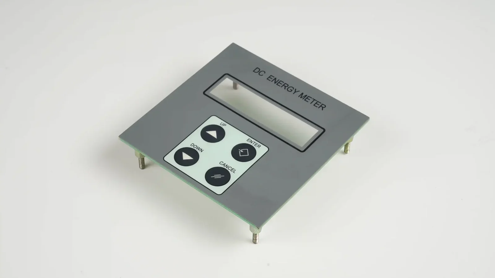
physical front surface, printed display window, touch or membrane input, PCB/FPC,
connector, adhesive, gasket, and enclosure interface. The quotation must still
state who supplies the display, who performs optical bonding, who owns the
bonding material and process, and who validates the installed display.
What Does Optical Bonding Mean in an HMI?
Optical bonding means filling the viewing-area gap between a cover lens, touch
sensor, and display with a transparent bonding material. The bond changes the
optical path and mechanically couples the parts. It is different from a narrow
adhesive frame around the display.
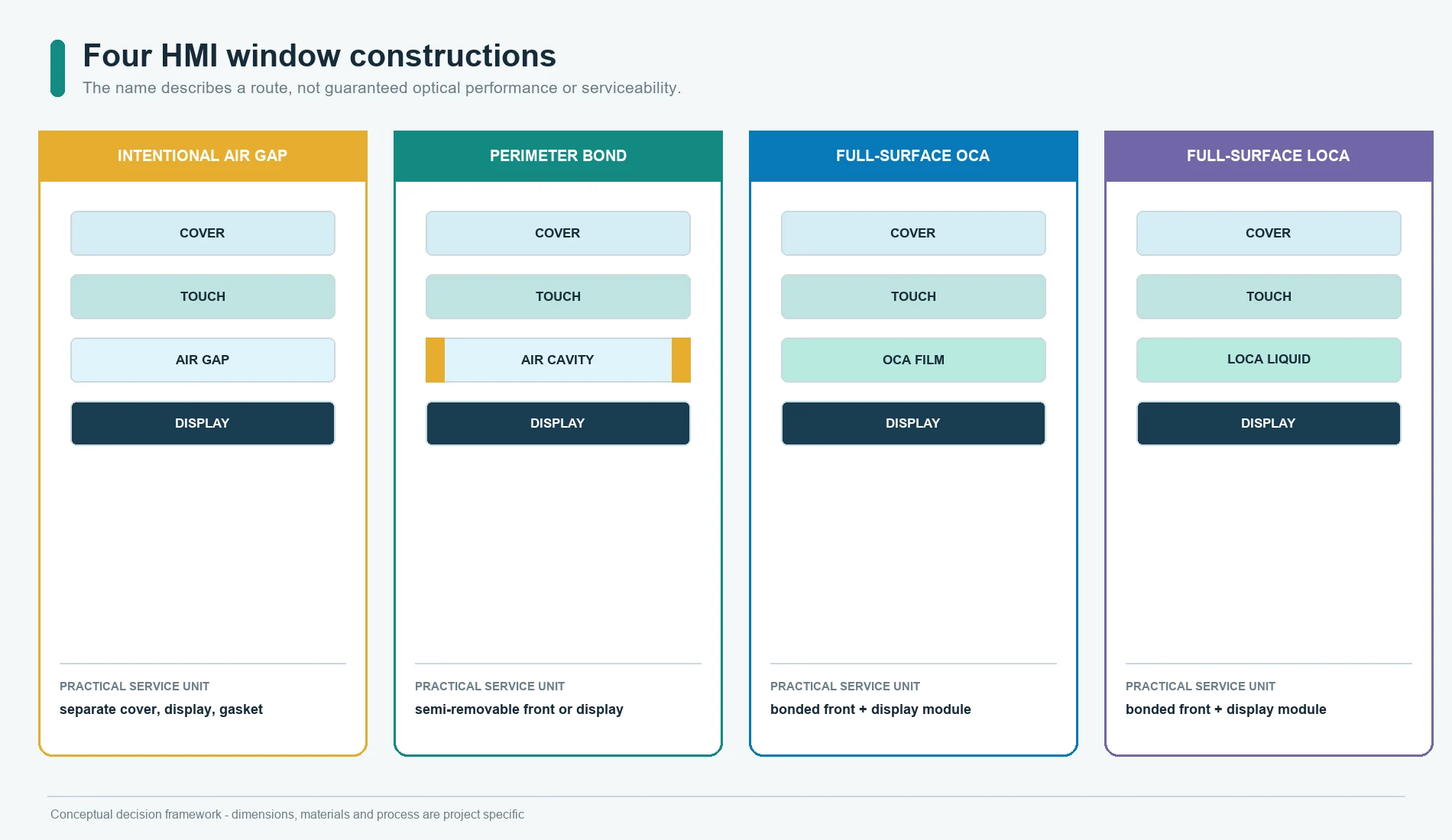
Four constructions are often confused:
| Construction | What occupies the viewing area | What it solves | What remains to control |
|---|---|---|---|
| Intentional air gap | Air between cover/touch layer and display | Display isolation, simpler assembly, easier replacement | Internal reflections, parallax, dust, condensation, gap uniformity |
| Perimeter bond or gasket | Air in the window; adhesive or gasket around it | Positioning, edge support, local sealing, removable or semi-removable assembly | Same optical air interfaces, spacer compression, vent or seal path |
| Full-surface OCA | Preformed optically clear adhesive film | Removes most of the designed air gap with a controlled film layer | Lamination, liner handling, bubbles, step coverage, flatness, material compatibility |
| Full-surface LOCA | Dispensed liquid optically clear adhesive cured after assembly | Fills the designed optical space and can suit non-planar or variable geometry | Dispense, flow, dam, bubbles, cure, shrinkage, shadow areas, contamination, rework |
These names describe construction routes, not guaranteed performance. A poorly
controlled full bond can be worse than a well-designed air-gap assembly.
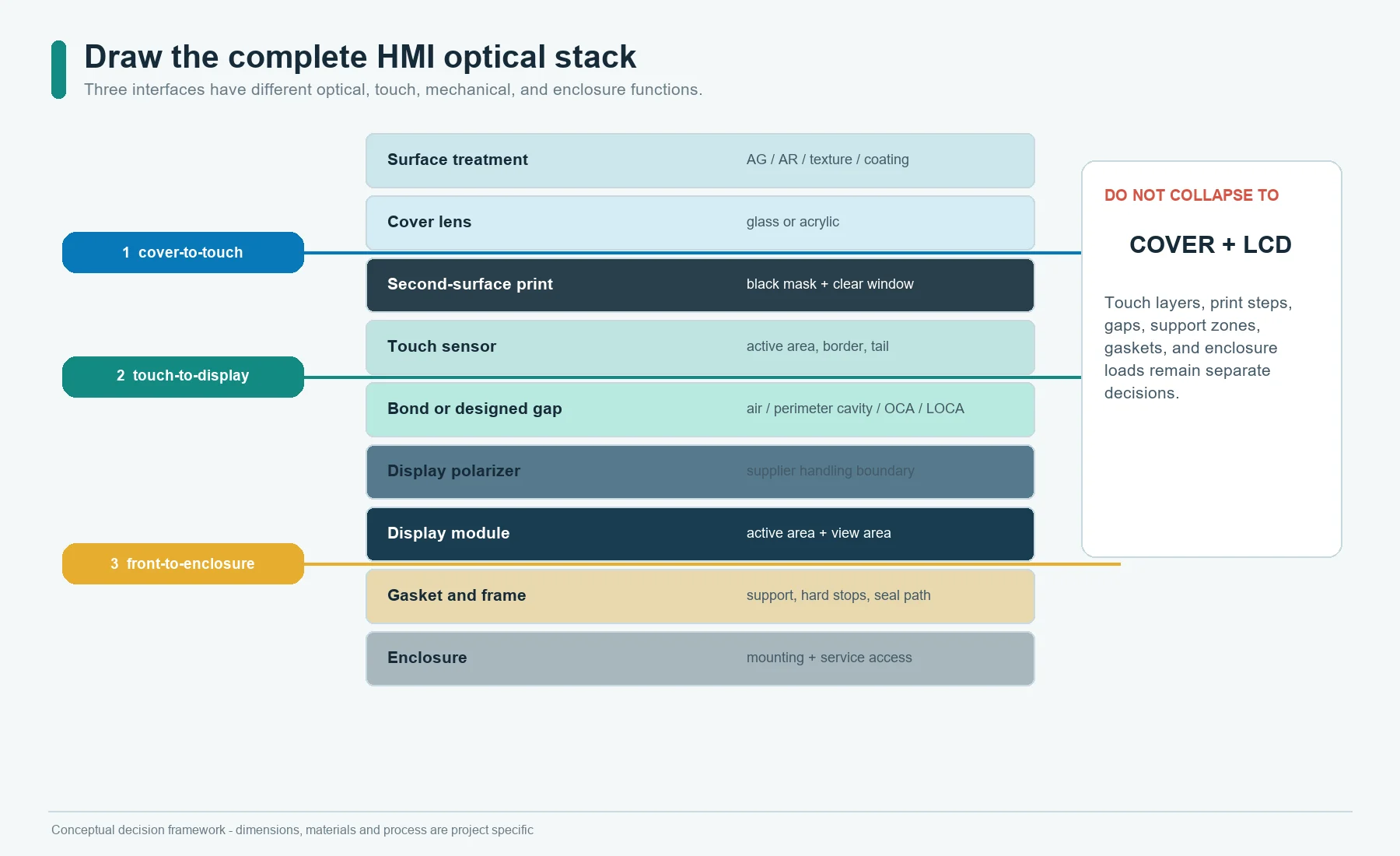
Draw the Complete Optical Stack Before Selecting a Bond
Start with a cross-section that includes every layer in the viewing path:
Ambient light and operator
        |
surface coating, texture, anti-glare or anti-reflective treatment
        |
glass or acrylic cover lens
        |
second-surface print, black mask and clear window
        |
touch sensor and its own bond layers, if present
        |
intentional air gap, perimeter cavity, OCA or LOCA
        |
display polarizer and display module
        |
support frame, bezel, gasket, PCB and enclosure
Do not collapse this into cover + LCD. The display may already include a touch
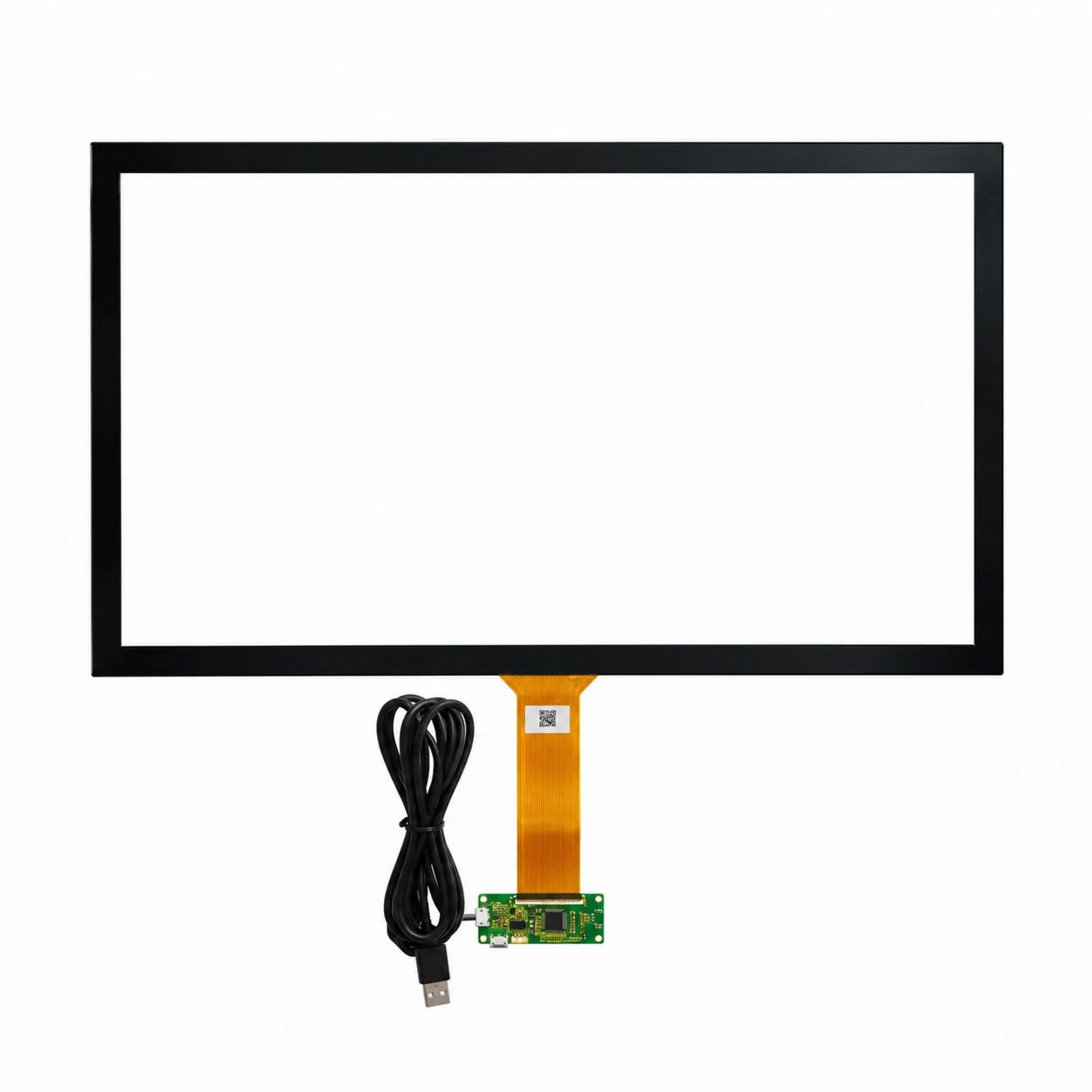
sensor. A separate projected-capacitive sensor may be bonded to the cover but
left above the display on an air gap. Another stack may fully bond the cover,
sensor, and display. Each interface has a different optical, electrical,
mechanical, and service function.
Separate three bond questions
Ask separately:
- Is the cover bonded to the touch sensor?
- Is the touch sensor bonded to the display?
- Is the cover or sensor attached to the enclosure around the perimeter?
The answer can be different at each interface. Calling the whole front
optically bonded without identifying the bonded surfaces hides the actual
process and failure boundary.
Why Does an Air Gap Change Display Readability?
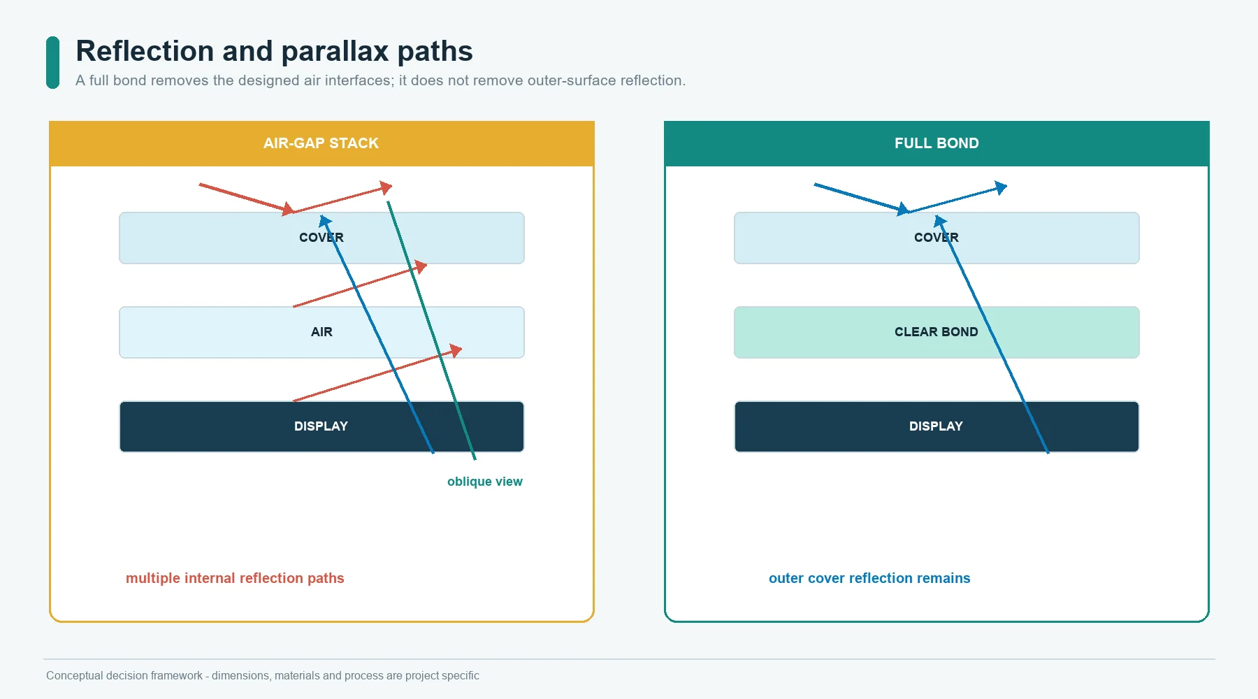
Light reflects when it crosses interfaces between materials with different optical properties. A cover-over-display air gap creates additional cover-to-air and air-to-display interfaces. Ambient light reflected from those interfaces competes with the displayed image. Filling the air gap can reduce internal reflections and improve perceived contrast.
The useful design conclusion is not a universal reflection percentage. It is:
- count the interfaces in the real stack;
- define ambient-light and viewing-angle conditions;
- compare an approved air-gap sample with the proposed bonded sample;
- evaluate black level, color, legibility, glare, and image uniformity; and
- keep the surface treatment in the comparison.
Optical bonding does not remove reflection from the outer cover surface. An
anti-glare texture, anti-reflective treatment, polarizer, tint, or display
brightness strategy may still be needed. Those choices can also change haze,
sharpness, color, fingerprints, cleanability, cost, and repair.
Air Gap, Parallax, and Touch Registration
Parallax is the apparent displacement between the visible image and the front
surface when the observer views the display from an angle. Increasing the
distance between the image plane and the cover surface generally makes this
offset more noticeable.
This matters when:
- a touch target must align with a displayed icon;
- the operator views the panel from above, below, or the side;
- a bezel masks part of the display;
- the HMI uses small status symbols or dense data;
- the product is mounted above or below eye level; or
- the cover is thick relative to the target geometry.
Do not approve only a straight-on photograph. Use the installed viewing cone,
operator posture, target size, touch accuracy, and enclosure angle. A bonded
stack can reduce the designed optical separation, but the touch controller,
display mapping, cover thickness, bezel, and software target still need
validation.
Newton Rings Indicate a Thin, Varying Optical Gap
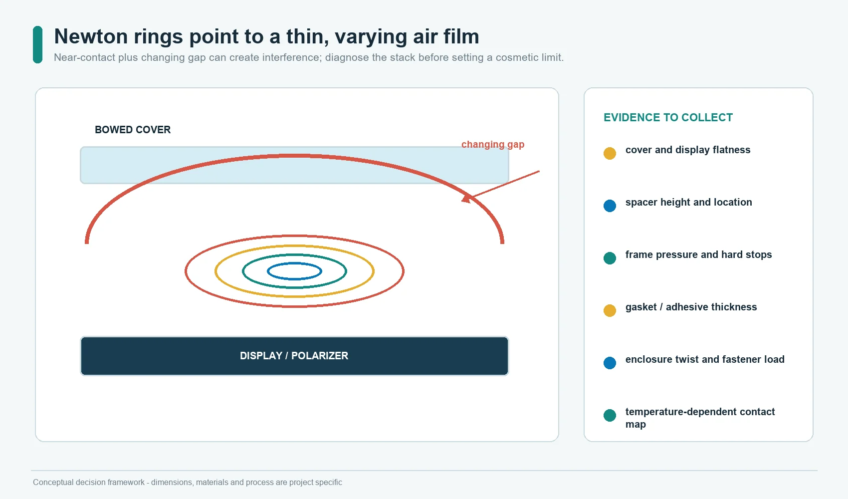
Newton rings are visible interference fringes formed when reflections interact
across a thin film whose thickness changes across the surface. Physics teaching
material demonstrates the effect using a varying air film between optical
surfaces.
In an HMI, ring-like or colored fringe patterns can indicate that two smooth
surfaces are almost touching while a thin, non-uniform gap remains. The pattern
may change with pressure, temperature, viewing angle, or assembly flatness.
Do not hide the symptom with a cosmetic acceptance limit before finding the
stack cause. Review:
- cover and display flatness;
- spacer height and position;
- local frame pressure;
- display polarizer contact;
- adhesive or gasket thickness;
- cover bow;
- enclosure twist; and
- thermal expansion across the assembly.
The corrective action may be a controlled larger gap, a full bond, a different
support method, or a flatness change. There is no universal spacer thickness
that prevents the pattern in every design.
Dust and Condensation Are Cavity Problems
An open or imperfectly sealed display cavity can collect dust. Moist air trapped in the cavity can also condense when surface temperatures cross the local dew point. Filling the optical gap can exclude dust and moisture from that space; it does not establish an enclosure seal.
That does not make the entire HMI waterproof. IEC 60529 assigns ingress
protection to an enclosure and its evaluated configuration, not to a loose cover
lens or adhesive layer.
For an air-gap or perimeter-bonded design, define:
- whether the cavity is vented, filtered, sealed, or pressure equalized;
- the assembly humidity and cleanliness condition;
- gasket joints, corners, fasteners, cable exits, and bezel openings;
- drainage and pooling direction;
- display heat and cold-surface locations;
- service opening and resealing method; and
- visual inspection after environmental exposure.
A perimeter adhesive frame can block one path while leaving another path through
the enclosure. Draw the cavity boundary instead of assuming the front window
controls the whole enclosure.
Compare the Four HMI Window Constructions
Intentional air gap
An intentional air gap can be the correct route when:
- the display must be removable;
- the display supplier already provides a finished module;
- optical requirements are moderate;
- the cover and display need mechanical isolation;
- the production process should avoid full-surface lamination;
- the display or cover may change during the product life; or
- field service has high value.
The gap still requires a drawing. Specify its datum, support surfaces, minimum
clearance under worst-permitted flatness, and the conditions in which contact is
not allowed. Check shock, vibration, pressure, enclosure flex, and temperature.
Perimeter bond or gasket
Perimeter attachment can locate the display or front assembly while preserving
an air cavity. It can also provide a replaceable joint if the adhesive or gasket
is designed for controlled removal.
Review:
- adhesive or gasket path;
- clear-window intrusion;
- frame width and corner geometry;
- compression range;
- local hard stops;
- cure or dwell before handling;
- display keepout areas;
- venting or cavity seal;
- peel access and service tools; and
- residue removal from the cover and display.
Perimeter bonding is not optical bonding. The viewing area still contains air.
Full-surface OCA film
Optically clear adhesive film is supplied as a controlled adhesive layer with release liners. OCA grades for transparent substrates, displays, and touch panels must be selected for the surfaces and process involved.
OCA can be attractive when:
- the bonded geometry is sufficiently flat;
- a preformed die-cut layer fits the window;
- film thickness and outline can be controlled;
- a liquid dispense and cure step is undesirable; and
- the lamination equipment can control particles, pressure, alignment, and
bubbles.
The material must match the actual substrates. Plastic covers require explicit compatibility and volatile-release review. A documented OCA family recommended for PC and PMMA cover lenses has been tested on those substrates, with resistance to bubbles from substrate outgassing reported for that family. Plastic-cover suitability is not automatic for every OCA.
Full-surface LOCA
Liquid optically clear adhesive is dispensed into the optical area and cured after the parts are aligned. Selected LOCA grades support cover-to-display bonding with glass and plastic substrate combinations and curved display designs. Flow, low shrinkage, bubble control, and rework capability are material-specific properties of light-curable display adhesives; validate the selected grade and process.
LOCA can be attractive when:
- the geometry is not well suited to a flat die-cut film;
- liquid flow is needed to fill the designed space;
- curved or free-form surfaces are involved;
- automated dispense and cure are part of the process plan; or
- a material supplier has qualified a compatible grade for the substrates and
display.
The process needs a dispense path, volume control, edge dam or containment plan,
bubble strategy, alignment fixture, cure access, cure verification, cleanup,
and rework method.
OCA and LOCA Require Controlled Processes
The adhesive data sheet is one input. Production performance also depends on:
- incoming cover and display flatness;
- surface energy and cleanliness;
- protective-film removal;
- particle control;
- material storage and conditioning;
- lamination or dispense sequence;
- pressure and support;
- cure energy and shadow regions for LOCA;
- liner release and die-cut quality for OCA;
- post-bond handling time;
- inspection lighting;
- environmental exposure; and
- lot and process traceability.
Two builds using the same adhesive can differ if the support fixture, cleaning,
display lot, cover flatness, cure, or handling changes.
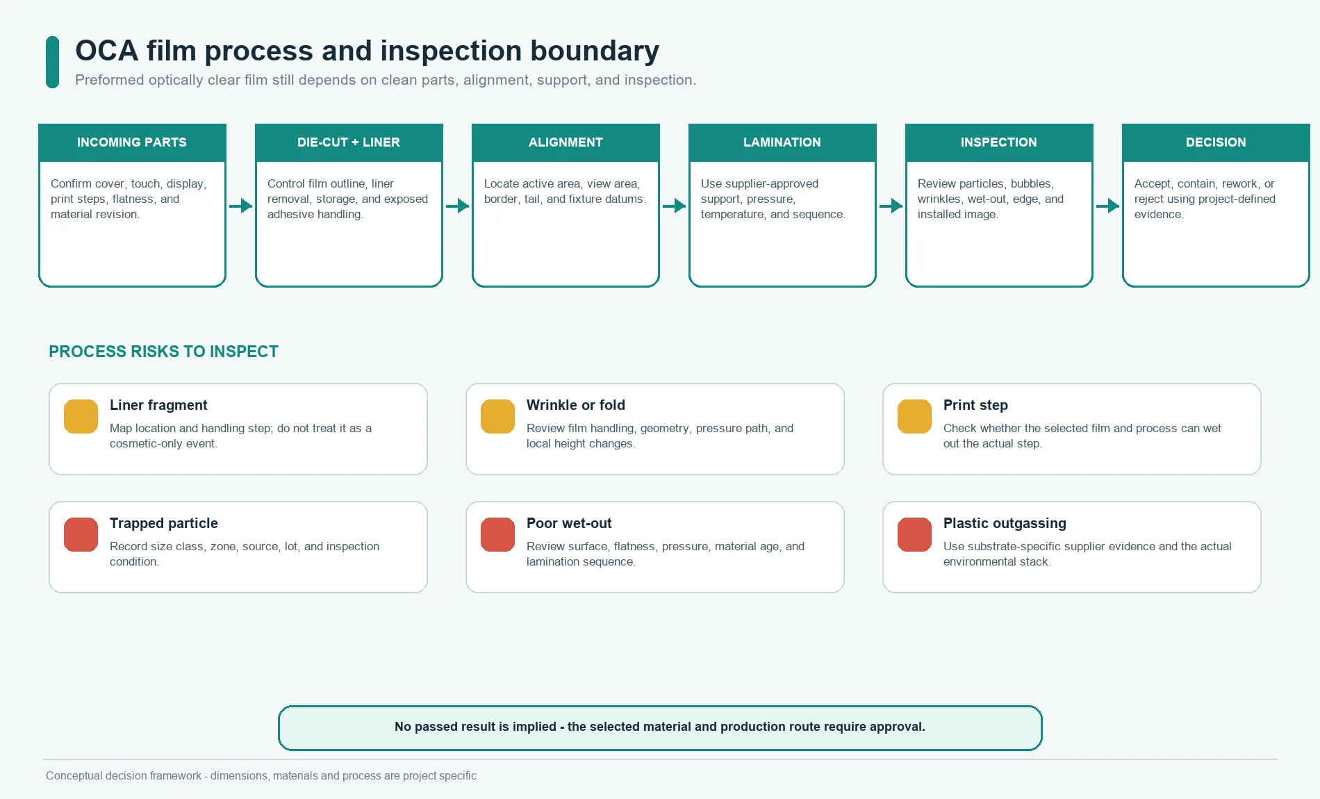
OCA process questions
Ask:
- Is the OCA compatible with the cover, touch sensor, display polarizer, print,
coating, and any ITO surface? - Can the film cover print steps and local height changes without leaving
voids? - Does the film outline avoid squeeze, contamination, and visible edges?
- What lamination pressure, temperature, equipment, and support are permitted
by the material and display suppliers? - How are particles, wrinkles, bubbles, misregistration, and liner fragments
detected? - What is the approved rework window and removal method?
Do not copy a material thickness from another display. Use the stack, step
height, flatness, substrate, and supplier process window for the actual program.
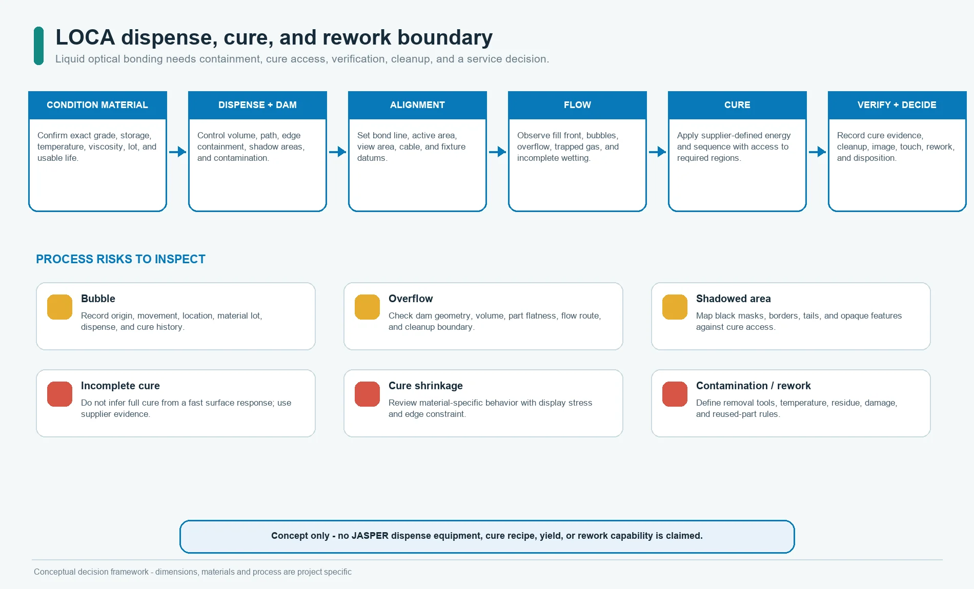
LOCA process questions
Ask:
- What viscosity and flow behavior are required for the gap and dispense path?
- How is the liquid contained before cure?
- Can UV or visible light reach every required cure area?
- How are shadowed borders, black masks, flexible circuits, and opaque features
handled? - How are dispense volume, bond-line thickness, bubbles, overflow, and
contamination measured? - What cure shrinkage, modulus, thermal expansion, yellowing, and rework
behavior does the supplier document for the selected grade?
Do not assume that a fast surface cure proves complete cure through the final
stack.
Cover Glass and Acrylic Change the Bonding Decision
The cover is not a neutral plate. It contributes flatness, stiffness, thermal
expansion, surface chemistry, edge risk, print steps, impact behavior, optical
finish, and service cost.
JASPER’s glass nameplate and dead-front glass
panel
route can provide a rigid printed surface, display window, hidden icon area, and
touch graphics. The acrylic panel and PMMA
cover
route can provide a lighter, machinable rigid front. The project must confirm
the exact grade, coating, print, bond surface, dimensions, flatness, and
environment rather than relying on the generic material name.
Glass review
Check:
- strengthened or non-strengthened material;
- edge finish, holes, notches, and handling;
- flatness and bow;
- second-surface print and black-mask steps;
- anti-glare or anti-reflective treatment;
- impact and mounting load;
- adhesive compatibility;
- differential expansion relative to the display and frame; and
- removal risk if the display must be serviced.
Acrylic review
Check:
- cast or extruded grade;
- hard coat and chemical exposure;
- flatness and creep under sustained load;
- moisture or volatile release relevant to the selected adhesive;
- print and coating compatibility;
- thermal expansion relative to the display;
- scratch and cleaning requirement; and
- fixture support during bonding and cure.
A plastic cover that looks flat at room temperature can behave differently after
heat, humidity, mounting stress, or long dwell. Evaluate the installed assembly,
not merely incoming parts on a granite table.

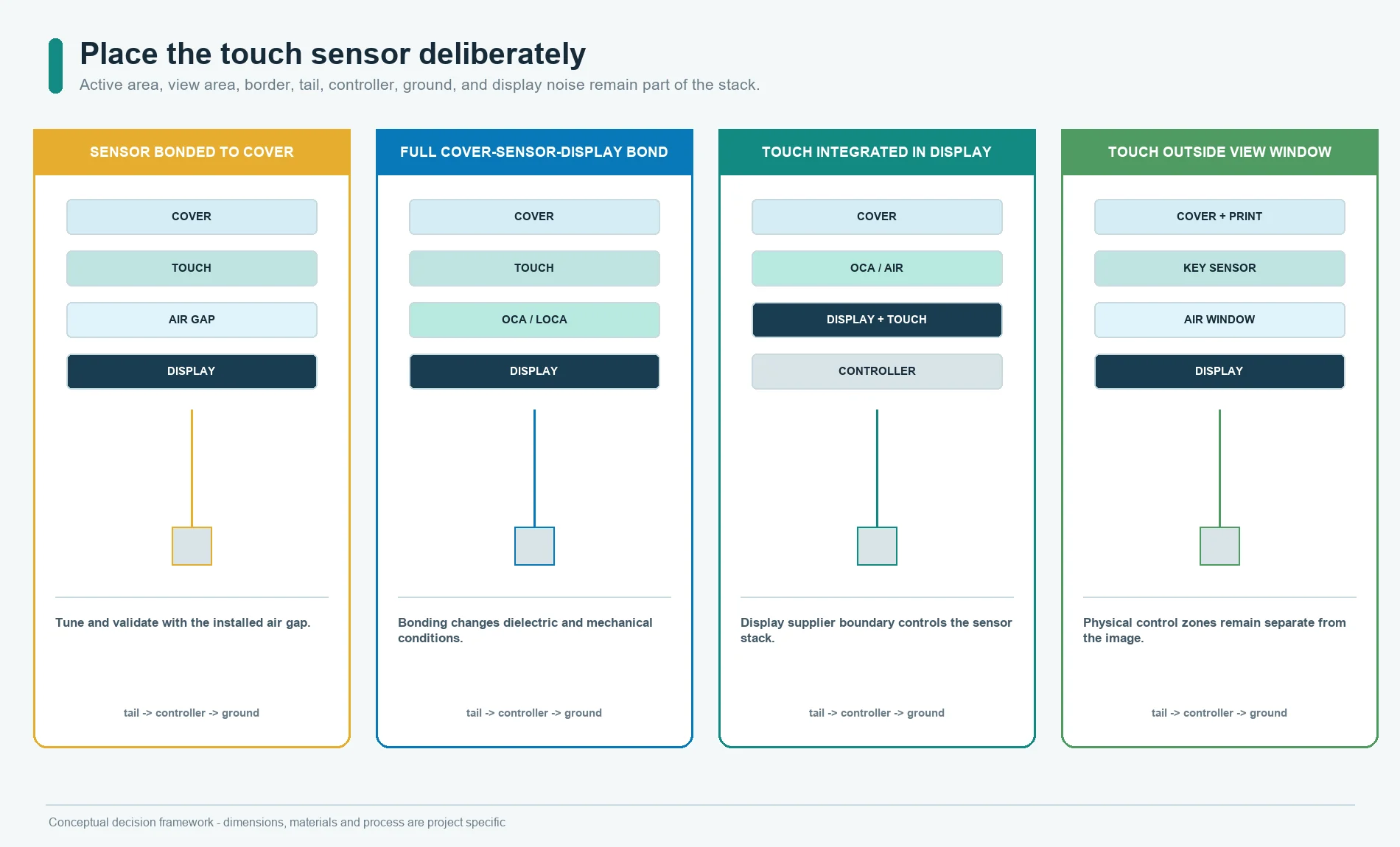
Place the Touch Sensor Deliberately
A touch-enabled HMI may use:
- cover lens bonded to a separate touch sensor, with an air gap to the display;
- cover lens bonded to a touch sensor, then optically bonded to the display;
- cover lens bonded directly to a display that contains the touch sensor; or
- a display window with touch controls located outside the image area.
The touch stack must be defined before the display bond. Overlay material, adhesive, transition layers, air gaps, moisture, sensor geometry, display proximity, and controller behavior are linked design inputs.
The current JASPER capacitive touch switch
guide
introduces the sensor, cover, grounding, lighting, moisture, and enclosure
questions. For the optical stack, add:
- touch active area versus display active and view areas;
- sensor border and tail exit;
- optical adhesive compatibility with the sensor;
- controller tuning before and after bonding;
- display noise and grounding;
- edge and corner touch behavior;
- screen-to-touch coordinate mapping; and
- rework risk to the sensor and display.
For the broader hardware boundary, review what an HMI panel includes. To coordinate the cover, sensor, tail, controller, and drawing package, use the custom capacitive touch panel design guide.
Prevent Display Stress and Mura
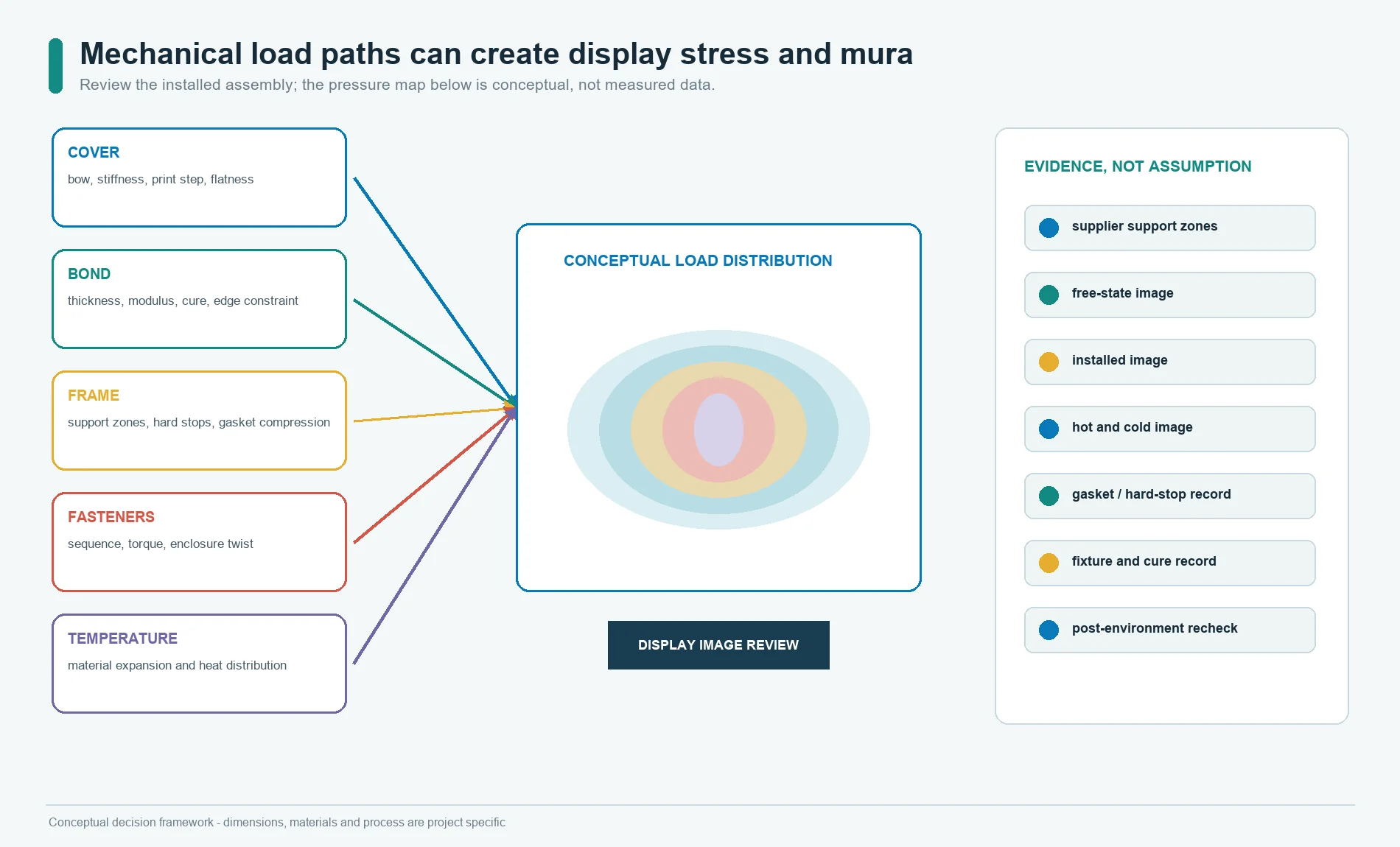
Mura is visible brightness or color non-uniformity across a display. Bonding can
contribute when the optical material, fixture, cover, frame, cure, or thermal
stack applies non-uniform stress to a sensitive display.
Review the complete load path:
cover flatness and stiffness
        +
bond material thickness, modulus and cure behavior
        +
display polarizer and cell sensitivity
        +
frame support, gasket compression and fastener torque
        +
temperature and material expansion
        =
installed display stress and image-uniformity risk
Controls should include:
- approved support zones from the display supplier;
- no-load and keepout regions;
- cover and frame flatness;
- bond-line uniformity;
- fixture pressure distribution;
- cure sequence;
- gasket compression and hard stops;
- fastener sequence and torque control where applicable;
- hot and cold image inspection;
- display test patterns selected for uniformity review; and
- recheck after environmental and mechanical exposure.
Do not use a rigid frame to flatten the display by force. Do not use the
adhesive to compensate for an uncontrolled mechanical stack. A soft adhesive can
still create local stress if thickness, cure, edge constraint, or support varies.
Control Foam, Gasket, Spacer, and Adhesive Thickness
Peripheral materials control the relationship between the cover, display, and
enclosure even when they are outside the visible image.
Specify:
- material and supplier grade;
- nominal thickness and tolerance;
- compressed thickness or hard-stop condition;
- outline, joints, corners, and cutouts;
- distance from the display active and view areas;
- surface preparation;
- assembly sequence and dwell;
- temperature and humidity conditioning;
- allowed squeeze or edge movement;
- vent, seal, drainage, or pressure-equalization function; and
- inspection method.
A foam frame that is taller on one side can tilt the display. A gasket compressed
by an uneven bezel can twist the module. A printed black mask or local ink step
can change the optical bond line. Put these features into one section drawing.
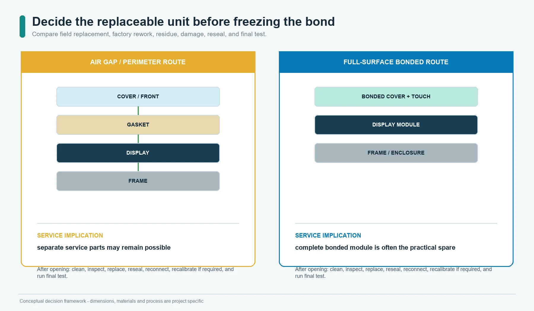
Decide the Replaceable Unit Before Freezing the Bond
Full-surface bonding usually changes a cover, touch sensor, and display from
separate service parts into one bonded module. The service team should know that
before tooling.
| Service question | Air gap or perimeter route | Full-surface optical bond |
|---|---|---|
| Can the display be removed alone? | Often possible if the perimeter joint and cable access are designed for it | Usually difficult; depends on validated separation and rework process |
| Is optical cleaning required after repair? | Yes, both cavity surfaces may need cleaning | Bond removal, residue control, and surface damage become the main risks |
| What is stocked as a spare? | Display, cover/front, gasket, and fasteners may be separate | Bonded display-front module may be the practical spare |
| Can the cover be reused? | Possible after inspection and adhesive cleanup | Not assumed; removal can damage cover, touch sensor, polarizer, coating, or print |
| What happens after opening? | Cavity cleanliness and resealing must be restored | Replacement module still needs enclosure seal and electrical validation |
| How is field time controlled? | More parts and alignment steps | Faster module swap if a complete bonded spare is available |
Define:
- field-replaceable unit;
- factory-repairable unit;
- allowed reused parts;
- separation tools and temperature limits;
- residue and solvent restrictions;
- polarizer, coating, print, and touch-sensor damage criteria;
- display calibration or touch remapping after replacement; and
- reseal and final test.
The lowest assembly cost can create the highest service cost if the replaceable
unit is discovered only after a field failure.
Prototype the Optical Stack in Stages
JASPER’s current prototyping
page is focused on membrane
switch and front-panel sample planning. Its useful principle is that a prototype
must answer named risks. It does not by itself prove an established JASPER
optical-bonding process or display-validation capability.
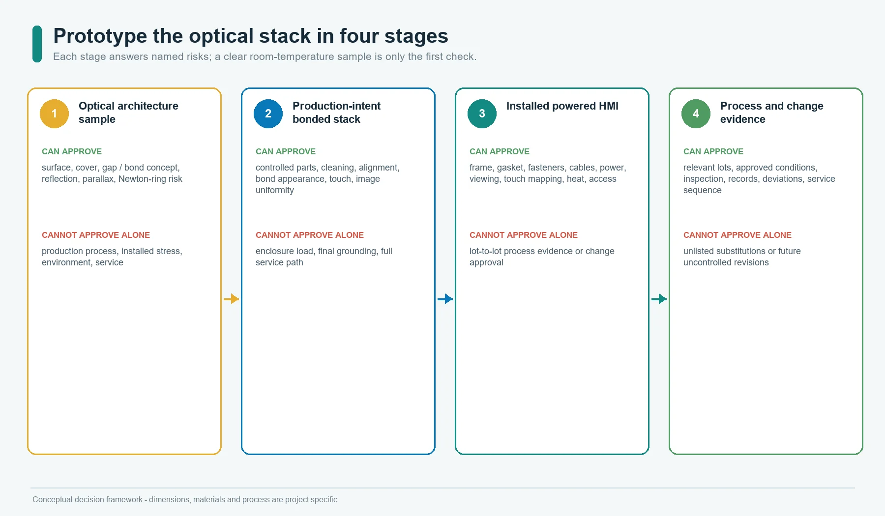
Use four stages:
Stage 1: Optical architecture sample
Compare surface finish, cover, air gap, perimeter frame, OCA, or LOCA concepts
using the intended display family. Evaluate reflection, glare, image contrast,
parallax, Newton rings, and view-angle behavior.
Stage 2: Production-intent bonded stack
Use controlled cover, print, touch sensor, adhesive, display, fixtures, cleaning,
lamination or dispense, and cure. Record bubbles, particles, alignment,
bond-line appearance, touch behavior, and image uniformity.
Stage 3: Installed HMI assembly
Install the stack in the real frame and enclosure with production-intent gasket,
fasteners, PCB, cables, power, grounding, and display settings. Evaluate stress,
touch mapping, viewing angle, thermal behavior, dust or moisture paths, and
service access.
Stage 4: Process and change evidence
Build across relevant material, display, cover, adhesive, and process lots.
Include approved environmental, mechanical, storage, cleaning, operating, and
service conditions. The program decides the sample count and acceptance plan.
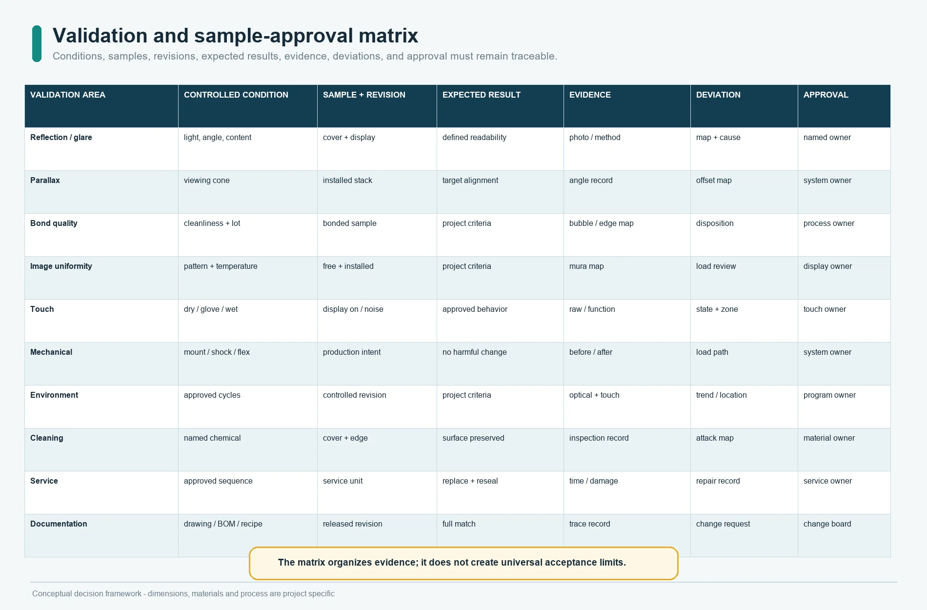
Use a Validation Matrix, Not a Single Beauty Sample
| Validation area | Controlled condition | Evidence to record | Typical failure signal |
|---|---|---|---|
| Optical readability | Ambient light, angle, content, brightness, surface state | Photos plus defined visual or instrument method | Washed black, reflection, glare, low contrast |
| Parallax and registration | Center, edge, corner, installed viewing cone | Image/window/touch alignment record | Apparent icon shift, masked pixels, touch offset |
| Bond quality | Cleanliness, material lot, process recipe, inspection lighting | Bubble, void, particle, edge and bond-line map | Bubble growth, edge lift, visible inclusion |
| Image uniformity | Test patterns, brightness states, temperature, frame condition | Mura or pressure-mark map | Bright/dark patch, color shift, pressure mark |
| Touch behavior | Dry, glove, moisture states, display on/off, noise states | Raw data or approved functional result | Missed touch, false event, edge error |
| Mechanical load | Mounting, torque, shock, vibration, enclosure flex | Before/after image and dimensional checks | Contact, crack, shift, bond damage |
| Thermal and humidity | Approved storage/operating cycles and dwell | Optical, bond, touch and image record | Condensation, bubble, delamination, distortion |
| Cleaning and chemicals | Named material, method, force, dwell, cycles | Surface, edge, print and bond inspection | Haze, coating loss, edge attack |
| Service | Approved removal and replacement sequence | Time, damage, residue, yield, final test | Polarizer damage, cracked cover, failed reseal |
| Documentation | Drawing, BOM, recipe, inspection and deviation records | Revision match and traceability | Unapproved substitution or process drift |
Acceptance limits must come from the OEM requirement, display supplier, bonding
material supplier, and confirmed production capability. The table does not
create universal limits.
Build Inspection Around the Failure Mechanism
Visual inspection should state:
- lighting type, intensity, angle, and background;
- display on/off state and test pattern;
- viewing distance and angle;
- active-area versus border criteria;
- bubble, void, inclusion, fiber, wrinkle, edge, and overflow categories;
- image-uniformity method;
- cosmetic versus functional disposition;
- sample conditioning before inspection; and
- photo or map requirements for deviations.
Dimensional and process inspection should include:
- cover and display datum alignment;
- window and active-area registration;
- bond outline and edge distance;
- stack thickness;
- cover and frame flatness;
- gasket or spacer condition;
- material lot and shelf-life status;
- lamination, dispense, cure, pressure, and fixture record;
- display and touch functional result; and
- rework history.
No visible bubbles is incomplete unless the viewing condition, area, size
class, process stage, and post-environment requirement are defined.
Lock Manufacturing Changes
Treat these as controlled changes:
- cover glass or acrylic grade;
- strengthening, hard coat, AG, AR, AF, tint, or other surface treatment;
- print ink, cure, black-mask thickness, or window transmission;
- touch sensor, tail, controller, firmware, or tuning;
- display manufacturer, model, polarizer, backlight, or revision;
- OCA or LOCA supplier, grade, thickness, lot, or storage;
- cleaner, primer, plasma, or surface preparation;
- lamination pressure, temperature, roller, autoclave, dispense, cure, or fixture;
- foam, gasket, spacer, frame, bezel, or fastener;
- enclosure material or flatness;
- rework method; and
- inspection lighting, test pattern, or acceptance rule.
An alternate display with the same outline may have a different polarizer,
surface, support limit, heat output, or sensitivity to pressure. Re-run the
affected optical, mechanical, touch, and environmental checks.
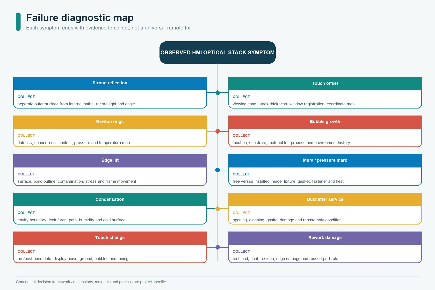
Diagnose Common Optical-Stack Failures
| Symptom | Possible stack cause | First review |
|---|---|---|
| Strong reflection or washed image | Air interfaces, outer surface, tint, haze, display brightness, ambient angle | Compare surface and internal reflections separately |
| Touch target appears offset | Cover thickness, air gap, viewing angle, display/window registration, software mapping | Installed viewing cone and coordinate map |
| Colored rings or moving fringes | Thin varying air film, local near-contact, bow, frame pressure | Flatness, spacer, contact and temperature map |
| Bubble after heat or humidity | Particle, poor wet-out, trapped gas, plastic outgassing, incompatible material, process drift | Bubble location, substrate, material lot and process history |
| Edge delamination | Surface preparation, bond geometry, stress, contamination, cover/frame movement | Edge load path and surface condition |
| Display pressure mark or mura | Non-uniform bond, fixture, frame, gasket, fastener, thermal mismatch | Image map with and without mounting load |
| Condensation in the window | Moist cavity, leak or vent path, cold surface, assembly humidity | Cavity boundary and dew-point condition |
| Dust after service | Uncontrolled opening, cleaning, gasket damage, reassembly environment | Service method and cavity inspection |
| Touch changes after bonding | Dielectric stack, bubbles, adhesive, display noise, ground, controller tuning | Pre/post-bond raw or functional comparison |
| Cover cracks during rework | Edge damage, tool load, heat, adhesive strength, unsupported cover | Approved separation fixture and reused-part rule |
Do not use this table as a remote root-cause diagnosis. It identifies the next
evidence to collect.
Choose by Product Requirement
Industrial indoor equipment
An intentional air gap or perimeter route may be adequate when ambient light is
controlled, the display is replaceable, and the cavity can remain clean. Validate
viewing angle, enclosure flex, vibration, and long-term cavity condition.
Outdoor or high-ambient-light equipment
Optical bonding deserves serious evaluation because internal reflection can
compete with the image. Surface treatment, display brightness, thermal load,
UV, seal, condensation, touch, and service still remain part of the system.
Medical-adjacent or frequently cleaned equipment
A continuous cleanable front may favor a bonded cover, but the project must
define cleaning chemicals, image readability, touch behavior, edge sealing,
service, and regulatory ownership. This article does not assign medical-device
compliance.
Vehicle, marine, or mobile equipment
Vibration, viewing angle, temperature, moisture, glove use, sunlight, service,
and display lifecycle can make a bonded route attractive. The system owner must
define the applicable environmental, optical, safety, and validation
requirements.
Service-intensive equipment
If displays are expected to be replaced during the product life, compare a
modular air-gap design against a complete bonded spare. Do not assume that a
reworkable adhesive makes field separation practical.
Stop the Design Review When Inputs Are Missing
Do not release the stack when:
- The display model and revision are not controlled.
- The display supplier has not approved the proposed contact, pressure,
lamination, or cure conditions. - The cover material, coating, print, and flatness are not defined.
- The touch sensor location and bond interfaces are ambiguous.
- OCA or LOCA is specified without an exact supplier grade and process.
- Plastic-cover outgassing or environmental compatibility has not been reviewed.
- The frame, gasket, fastener, and enclosure load path is missing.
- The viewing requirement is only
looks clear. - The replaceable unit and rework rule are unknown.
- The prototype does not use the real display, cover, touch, bond, and frame.
- Mura, bubble, dust, condensation, touch, and service acceptance are undefined.
- A loose cover or bond is being assigned an enclosure IP rating.
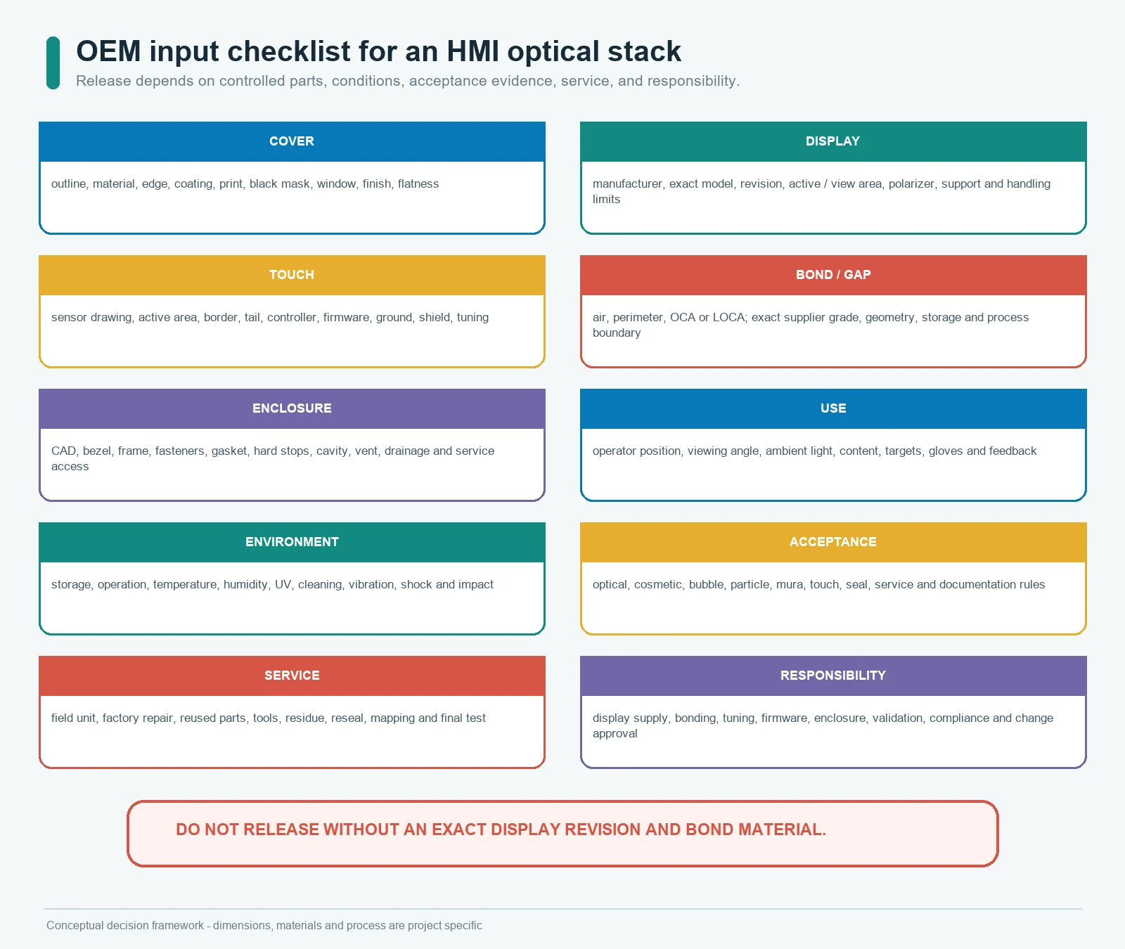
OEM Input Checklist
Send:
- Cover outline, material, thickness concept, edge, coating, print, black mask,
clear window, surface finish, and flatness requirement. - Display manufacturer, exact model, revision, active area, view area, outline,
polarizer, mounting, cable, support, pressure, temperature, and supplier
handling limits. - Touch sensor drawing, active area, border, tail, controller, firmware, ground,
shield, and current tuning status. - Proposed air gap, perimeter adhesive/gasket, OCA, or LOCA supplier and grade.
- Enclosure CAD, bezel, frame, fasteners, gasket, hard stops, cavity, vent,
drainage, mounting angle, and service access. - Operator position, viewing angle, ambient light, target content, touch targets,
gloves, and feedback. - Storage, operating, temperature, humidity, UV, cleaning, vibration, shock,
impact, and other program conditions. - Optical, cosmetic, bubble, particle, image-uniformity, touch, seal, and service
acceptance rules. - Prototype quantity, annual volume, display supply model, spare strategy, and
product-life assumptions. - Responsibility matrix for display supply, optical bonding, touch tuning,
firmware, enclosure validation, compliance, repair, and change approval.
The input package should identify assumptions in a separate list. Hidden
assumptions become late tooling or validation changes.
Frequently Asked Questions
Is optical bonding always better than an air gap?
No. Optical bonding can reduce internal reflections, parallax, and contamination
inside the viewing gap. It adds material, process, stress, yield, inspection,
and service requirements. An intentional air gap can be better for a moderate
optical requirement and a replaceable display.
Is perimeter bonding the same as optical bonding?
No. Perimeter adhesive or a gasket attaches the parts around the window while
air remains in the viewing area. Full-surface optical bonding fills the viewing
gap with a transparent material.
What is the difference between OCA and LOCA?
OCA is commonly a preformed optically clear adhesive film with release liners.
LOCA is a dispensed liquid optically clear adhesive that is cured after
alignment. Material chemistry, equipment, substrates, geometry, cure, and
rework determine which route fits the project.
Does optical bonding eliminate glare?
It can reduce internal reflections from the removed air gap. Reflection from the
outer cover surface remains. Surface texture, coating, polarizer, tint, display
brightness, and ambient geometry still affect glare and readability.
Can acrylic be optically bonded to a display?
Potentially, but the exact acrylic, coating, print, adhesive, outgassing,
flatness, thermal expansion, environment, and process must be compatible. Use a
material grade documented for the selected plastic substrate and validate the
actual assembly.
Can the display be replaced after optical bonding?
Sometimes in a controlled factory rework process, depending on adhesive,
substrates, tools, temperature limits, and damage criteria. Do not assume that
the cover, touch sensor, display polarizer, or display can be reused. Define the
service unit before design release.
Does a full optical bond create an IP rating?
No. It can remove one internal gap, but ingress protection belongs to the
evaluated enclosure, including cover attachment, bezel, gasket, fasteners,
cables, openings, and assembly process.
Why can bonding create display mura?
The display can show non-uniformity when bond thickness, cure, fixture pressure,
cover flatness, frame load, gasket compression, fastener load, or thermal
expansion applies uneven stress. Validate the bonded display both free and
installed, across the program conditions.
What should an optical-bonding prototype prove?
It should prove the actual optical stack, reflections, parallax, image
uniformity, bubbles, particles, alignment, touch behavior, frame stress,
environmental response, and service plan. A clear room-temperature sample is
only the first check.
Sources
- JASPER Electronics, “HMI Assembly.”
https://www.jasperele.com/products/hmi-assembly/ - JASPER Electronics, “Glass Nameplates and Dead-Front Glass Panels.”
https://www.jasperele.com/products/graphic-overlays/glass-nameplate/ - JASPER Electronics, “Acrylic (PMMA) Panels and Nameplates.”
https://www.jasperele.com/products/graphic-overlays/acrylic-panels/ - JASPER Electronics, “Capacitive Touch Control Panel for a Sealed Interface.”
https://www.jasperele.com/case-studies/capacitive-touch-control-panel/ - JASPER Electronics, “Membrane Switch Prototyping.”
https://www.jasperele.com/capabilities/prototyping/
Request an HMI Optical-Stack Review
Send the cover drawing, display model and revision, touch-sensor drawing,
enclosure section, proposed air gap or bond, viewing conditions, environmental
requirements, and service strategy through the JASPER RFQ
form. Ask for a written scope that
separates cover manufacture, touch integration, display supply, optical bonding,
enclosure assembly, tuning, inspection, validation, and compliance before the
prototype is quoted.
Ready to Start Your Project?
Tell us about your membrane switch, keypad, or graphic overlay requirements. Our engineering team will review your specifications and provide a detailed quote.