
HMI hardware guide for OEM teams
What Is an HMI Panel? Hardware Layers and OEM Integration
An HMI panel is the operator-facing hardware used to show machine status and receive commands. Its physical stack can include graphics, keys or touch sensing, a display window and module, circuit, connector, gasket, and enclosure interface. Runtime software, PLC logic, safety logic, and final machine validation remain separate unless the project assigns them.
JASPER’s custom HMI assembly scope is the physical operator interface: the parts a user sees, touches, presses, reads, cleans, and installs into equipment. An OEM should provide the enclosure datums, operator tasks, input method, display and electronics ownership, connector interface, environment, mounting method, and validation requirements before that front-panel stack is frozen.
Why “HMI Panel” Needs a Project Definition
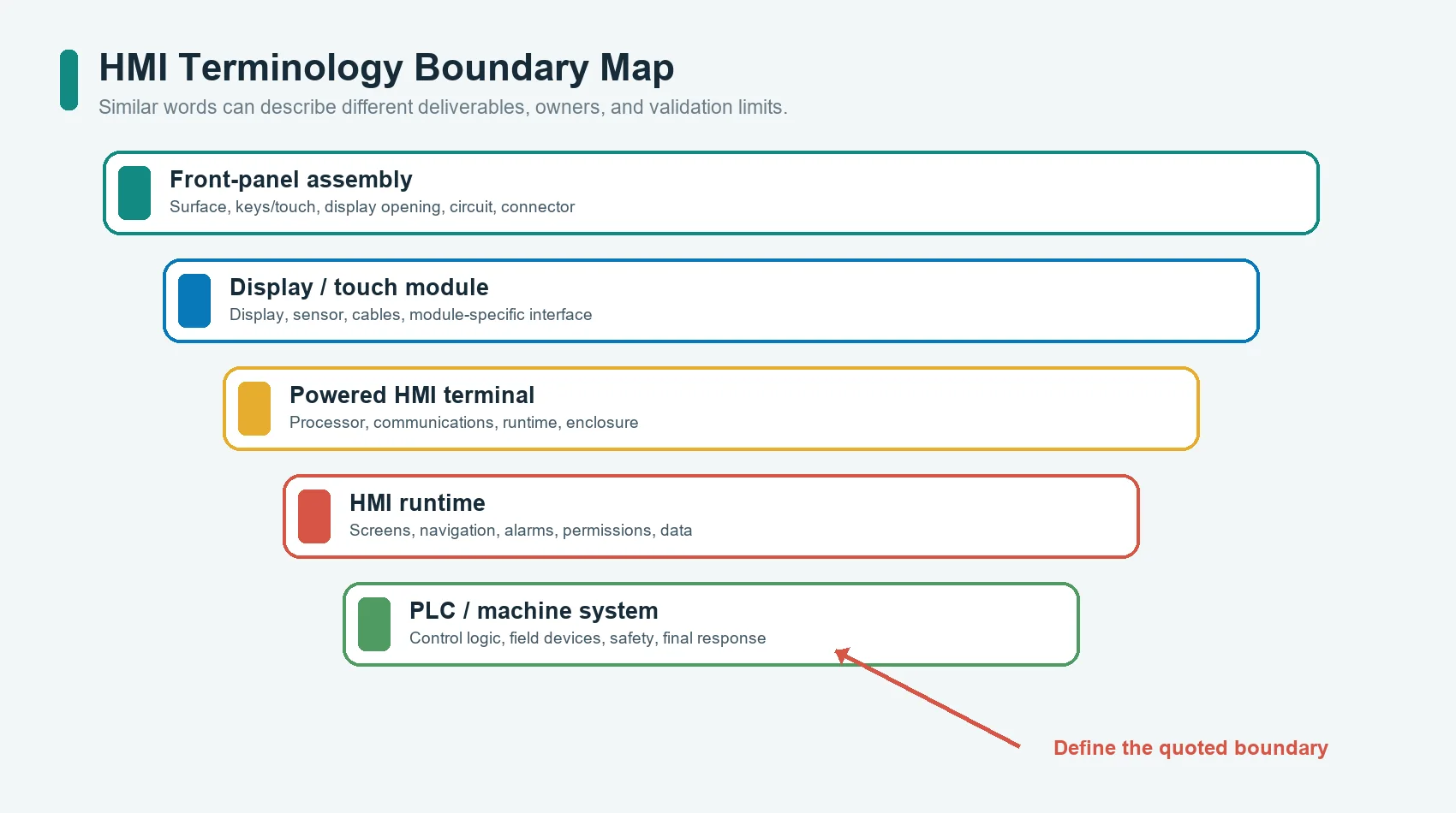
HMI means human-machine interface. The phrase describes a function, not one
universal part number or architecture.
In a control-system discussion, an engineer may use HMI for the graphical
screens, navigation, alarm behavior, user permissions, and runtime connected to a
PLC. In a mechanical drawing, HMI panel may mean the bezel, cover lens, membrane
keypad, display window, gasket, and connectorized front assembly. A purchasing
team may use the same phrase for a complete branded terminal that already contains
the display, processor, operating system, runtime, communications, and enclosure.
All three uses are common. Trouble starts when a quotation, drawing, or responsibility matrix uses the word without stating which one is intended.
| Buyer or engineering term | Physical content that may be included | Content that may remain outside the part |
|---|---|---|
| HMI panel | Front surface, keys or touch layer, display opening, indicators, circuit, connector, gasket | Display electronics, processor, runtime, PLC logic |
| HMI front-panel assembly | Operator-facing layers and their mechanical/electrical interconnection | Machine controller, cabinet wiring, software, final system validation |
| HMI terminal | Display, touch input, processor, communications, runtime, enclosure | PLC program, field devices, machine safety system |
| Operator interface | Functional description of how the user receives information and gives commands | No fixed hardware boundary unless the project defines it |
| Control panel | May include the HMI plus switches, lamps, emergency controls, wiring, and enclosure | Depends on panel-builder and OEM scope |
| Display module | LCD or another display with its own mechanical and electrical interface | Cover lens, touch sensor, front graphics, enclosure, application software |
ISA101 covers HMI work such as screen navigation, graphics, alarms, security, and interfaces to programs and databases in manufacturing applications.[4] That is a useful reminder that the complete HMI discipline extends beyond the front-panel hardware. The BOM and drawing should identify the physical assembly separately from the screen and control-system responsibilities.
An HMI Is a Chain, Not a Single Surface
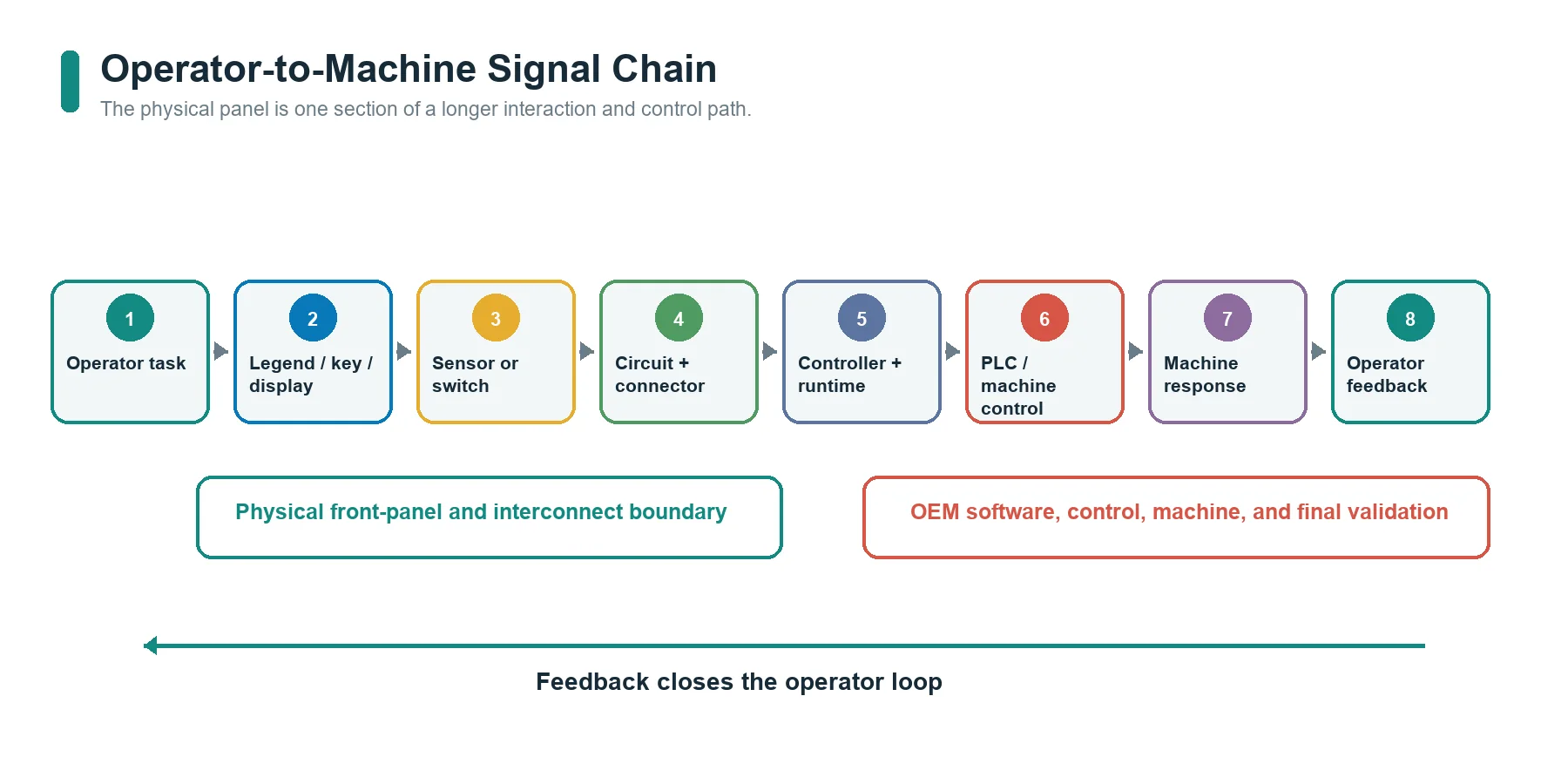
The operator does not interact directly with a PLC register or display pixel. A physical and logical chain sits between the person and the machine.
Operator task
    -> visible legend, icon, key, touch target, display, or indicator
    -> physical input or viewing layer
    -> sensor, switch, circuit, connector, or display interface
    -> controller input and HMI runtime
    -> PLC, machine control, communications, and field devices
    -> machine response
    -> visual, tactile, audible, or haptic feedback to the operator
Each arrow is an interface that needs an owner.
For example, a printed START icon may be owned by the graphic artwork, but its
touch target belongs to the sensor design, its channel belongs to the circuit and
connector map, its accepted state belongs to the controller, its permission logic
belongs to software, and the machine motion belongs to the control system. The
front-panel supplier cannot validate the final command by inspecting only the
printed icon.
ISO 9241-210 addresses human-centred design for interactive systems and explicitly recognizes that both hardware and software components affect the interaction.[5] For an OEM project, this means the operator task and use context should be defined before the team debates only materials, colors, or display size.
What Hardware Layers Can an HMI Panel Contain?
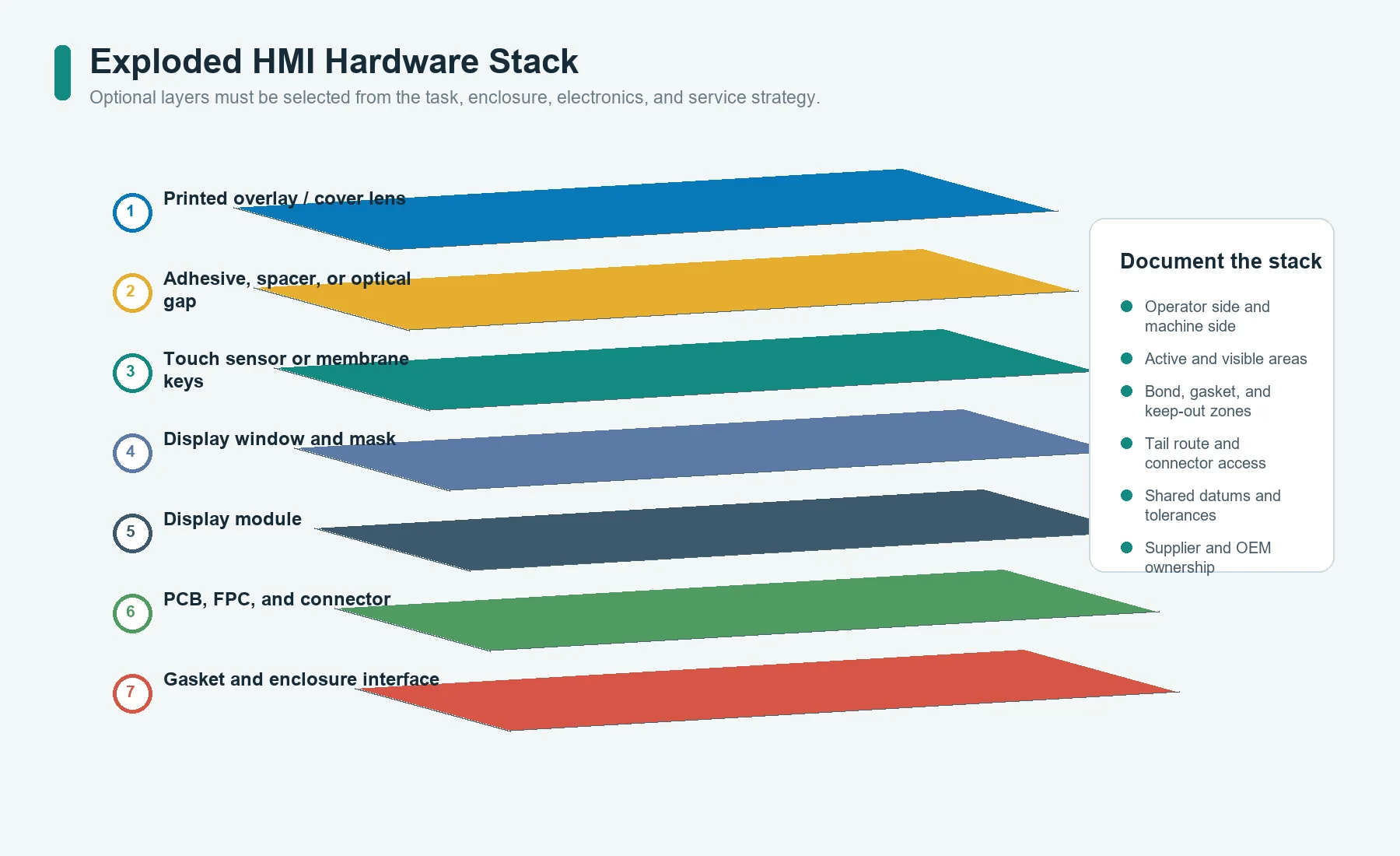
An HMI panel does not always contain every layer below. The stack is selected from the operator task, display architecture, enclosure, electronics, environment, and service strategy.
| Layer or component | Primary function | Critical interface to define |
|---|---|---|
| Printed overlay, rigid face, or cover lens | Legends, icons, warnings, branding, cleanable user surface | Artwork, color, finish, chemical exposure, viewing area |
| Tactile key, membrane switch, silicone key, or touch sensor | Converts an operator action into an electrical input | Target size, force or touch behavior, channel map, feedback |
| Spacer, carrier, adhesive, or optical gap | Controls separation, bonding, support, and alignment | Thickness stack, cutouts, flatness, bond area, rework plan |
| Display window | Provides a protected visual path to a display | Active area, visible area, bezel mask, tolerance, parallax |
| Display module | Generates visual information | Outline, active area, mounting, power, data interface, heat |
| Indicator or backlight | Provides status, guidance, or visibility | Location, color definition, brightness target, light isolation |
| PCB, FPC, printed circuit, or wiring | Routes input, lighting, display, and connector signals | Pinout, current, voltage, bend area, grounding, test points |
| Controller or interface board | Scans inputs, drives outputs, conditions signals, communicates | Firmware ownership, protocol, diagnostics, update path |
| Connector, tail, or cable | Connects the panel to the host electronics | Mating part, orientation, retention, route, service access |
| Gasket, rear adhesive, bezel, or enclosure | Positions and protects the assembly | Datum scheme, compression, surface, fasteners, ingress boundary |
A stack should be documented as a cross-section as well as an exploded visual. A useful cross-section identifies:
- operator side and machine side;
- display active area and visible opening;
- touch or key sensing plane;
- graphic and masking layers;
- adhesive and gasket bond areas;
- PCB or FPC support;
- connector and tail exit;
- enclosure ledge, fastener, or mounting surface;
- critical gaps, compression zones, and keep-out areas; and
- which dimensions are controlled by the panel supplier, display supplier, and OEM enclosure.
The Front Surface Is a Functional Part
The visible surface is not decoration added after the electronics are complete. It carries instructions, identifies states, controls the viewing path, protects the input layer, and establishes what the operator can find under real lighting, glove, cleaning, and posture conditions.
Graphics and task mapping
Every key or touch target should map to a defined task and channel. Artwork should identify:
- normal commands;
- status and warning information;
- values or units that must remain visible;
- keys that change function by screen;
- restricted or safety-related actions;
- indicator locations;
- display masks and inactive borders;
- language and symbol requirements; and
- service or maintenance information.
The artwork file, circuit map, display layout, and software screen should use the
same naming convention. If one file calls a channel K3, another calls it
RESET, and the software calls it input_07, a late integration error becomes
more likely.
Surface, cleaning, and viewing conditions
The project should define the actual cleaning agents, contact wear, expected
contaminants, indoor or outdoor exposure, and viewing angles. A generic statement
such as industrial environment is not enough to select a surface, print system,
coating, adhesive, or sealing detail.
JASPER’s industrial control application page shows the type of machine-control context in which labels, tactile location, display visibility, cleaning, connector routing, and enclosure fit must be reviewed together. The final requirements still belong to the specific equipment program.
Input Methods: Keys, Touch, or Both
The HMI input method should follow the operator task rather than a preference for a flat or modern-looking surface.
Membrane keys
A membrane switch can provide discrete electrical contacts in a thin front-panel construction. Tactile domes can give a physical snap; non-tactile zones can keep a flatter feel. This route suits commands that benefit from fixed positions, repeatable key locations, simple matrix behavior, or operation without a display.
The design still needs approved actuation behavior, circuit mapping, overlay geometry, tail route, connector, support, and enclosure details. A tactile dome does not correct a flexible support surface or a key that sits outside the operator’s natural reach.
Silicone or mechanical keys
Raised keys can improve finger location, travel, and glove use. They add height, moving geometry, support, and sealing interfaces. The OEM should define whether the keymat, PCB, housing, light guide, and retention features are one supplied assembly or separate parts combined by the final assembler.
Capacitive touch
Capacitive touch can create a continuous front surface with no key travel. The controller, electrode layout, cover material, cover thickness, bonding, nearby conductors, grounding, shielding, moisture behavior, glove requirement, and firmware tuning all affect the result.
Microchip’s capacitive touch design guidance treats touch-cover effects and shielding as sensor-design inputs, not cosmetic afterthoughts.[7] A thicker or changed cover can alter the relationship between the finger and electrode, while tracks or unintended touch areas may require shielding. Therefore, the cover lens, sensor, controller, enclosure, and tuning responsibility must be reviewed as one chain.
Hybrid input
An HMI can combine a display, capacitive touch, membrane keys, emergency controls, and indicators. Hybrid designs are useful when frequent or contextual actions belong on the screen while critical, repeated, or gloved actions benefit from fixed physical keys.
The presence of a touchscreen does not automatically eliminate physical controls. The OEM should decide which actions must remain available if the display is unreadable, the software is changing screens, or the operator cannot look directly at the interface.
Display Window, Touch Sensor, and Display Module Are Different Parts
These terms are often merged in early discussions.
Display window
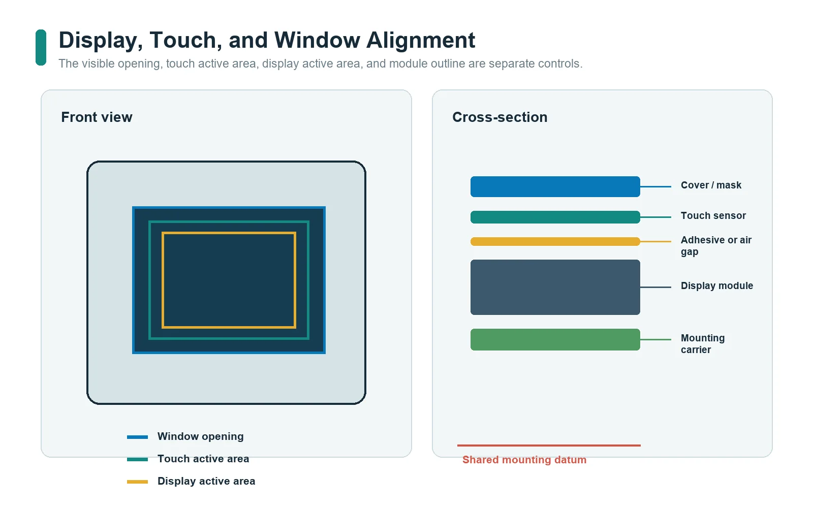
A display window is the transparent or open viewing region in the front surface. It can include a printed mask, hard surface, clear adhesive, air gap, gasket, or other optical/mechanical details. It does not generate an image.
Define:
- display active area;
- display visible area;
- window opening and mask overlap;
- alignment tolerance;
- viewing angle;
- surface finish and reflections;
- allowable air gap or bonding method;
- cleaning and scratch requirements; and
- assembly and replacement strategy.
Touch sensor
The touch sensor detects operator contact or position. It may be separate from the display and may use its own FPC, controller, grounding, and tuning. The touch active area and the display active area do not become aligned merely because their nominal diagonal size matches.
Display module
The display module generates the image. It has its own outline, active area, mounting features, power, signal interface, connector, operating limits, backlight, thermal behavior, and lifecycle.
Before tooling the front panel, the OEM should provide the actual display drawing and revision. A web listing, nominal screen size, or screenshot is not enough to control the visible opening and mounting stack.
Complete display-touch module
Some projects source a display and touch sensor as a bonded module. Others assemble the cover lens, touch sensor, and display separately. The drawing should state who owns:
- touch-to-display alignment;
- cover-to-touch bonding;
- display mounting;
- optical acceptance;
- touch tuning;
- cable routing;
- module test;
- repair or replacement; and
- warranty responsibility.
This Resource does not prescribe air-gap versus optical-bonding parameters. That decision requires a separate optical, mechanical, process, cost, and service review.
Circuit, Controller, and Connector Boundaries
The physical front surface becomes useful only when its channels connect correctly to electronics.
PCB, FPC, and printed circuit
A circuit layer may route:
- discrete key contacts;
- touch electrodes;
- LED power and control;
- display power and data;
- communication;
- ground and shield connections;
- test points;
- identification or configuration signals; and
- connector pins.
The drawing should distinguish a passive routing circuit from an active controller board. A PCB behind a front panel does not necessarily mean the panel supplier owns firmware, communications, or machine logic.
Controller board
A controller may scan keys, process touch measurements, drive indicators, manage a display, or communicate with the host. Define:
- hardware owner;
- schematic and layout owner;
- component and firmware owner;
- programming method;
- communication interface;
- boot and update behavior;
- diagnostic behavior;
- electrical test responsibility; and
- final software validation.
If the OEM supplies the controller, the front-panel drawing must still identify mechanical mounting, connector location, grounding, and the electrical interface. If a supplier integrates the board, the quotation should state exactly which functions and tests are included.
Connector and service access
Connector selection is an integration decision, not a tail-end purchasing detail. Review:
- mating connector and pin numbering;
- insertion direction;
- latch and retention;
- cable or tail route;
- bend and strain relief;
- assembly sequence;
- access after the display or enclosure is installed;
- electrical clearances and keep-outs;
- test access; and
- field replacement requirements.
An electrically correct connector can still be unusable if the enclosure blocks the latch or forces the tail through a sharp fold.
Enclosure, Mounting, Gasket, and Sealing
The front panel and enclosure form one mechanical boundary.
Possible mounting methods include rear adhesive, gasket compression, bezel capture, studs, screws, clips, brackets, or combinations. The correct choice depends on panel size, surface material, flatness, service strategy, load, display mass, environment, and assembly sequence.
Use shared datums
Define at least:
- panel outline datum;
- display center or active-area datum;
- key or touch target datum;
- enclosure opening;
- fastener or locating features;
- connector and tail exit;
- gasket path;
- keep-out zones; and
- tolerance owner for every mating feature.
Without shared datums, the overlay, touch sensor, display, PCB, and enclosure can each meet an individual drawing while the assembled interface still appears misaligned.
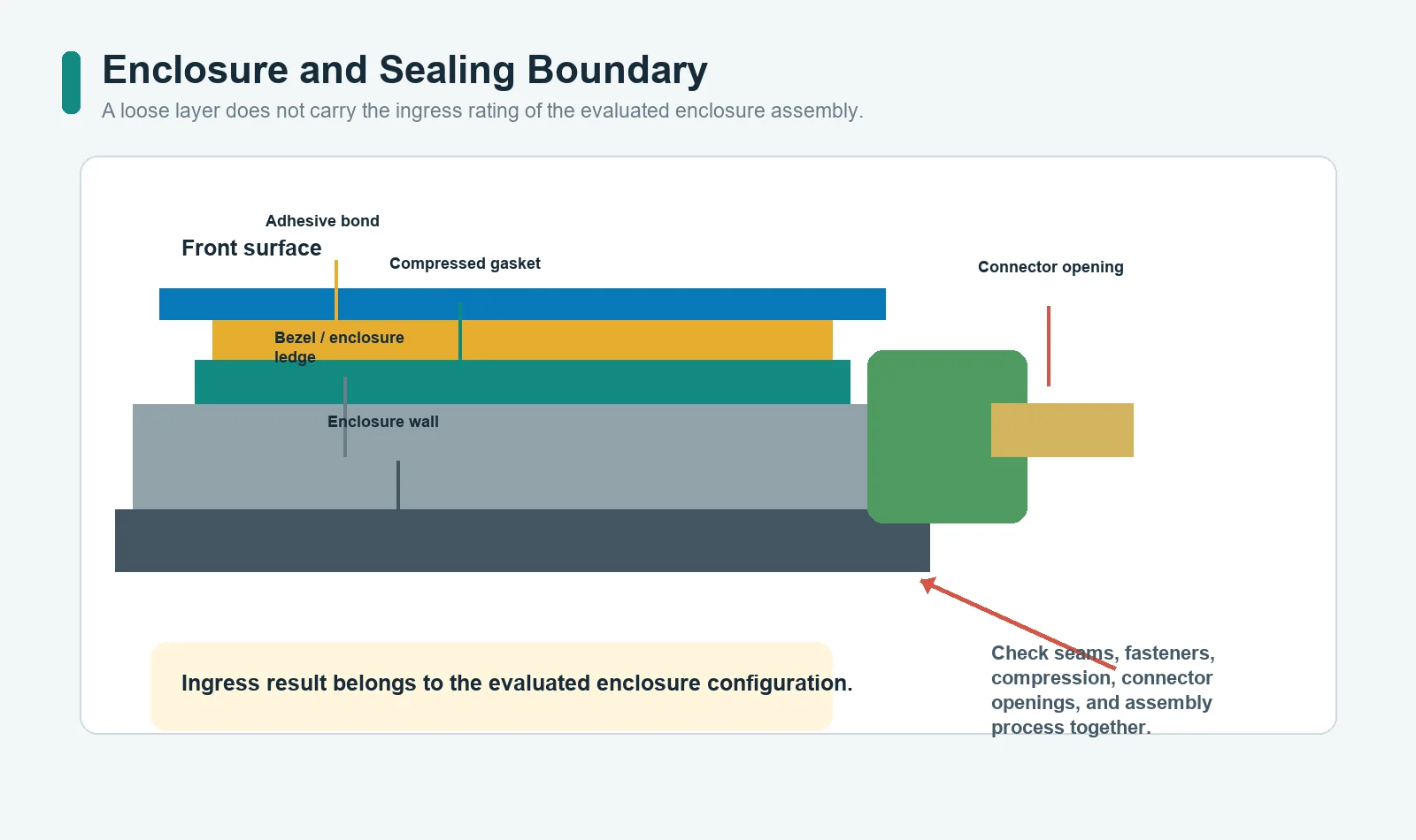
Do not assign an IP rating to a loose layer
IEC 60529 classifies degrees of protection provided by enclosures.[6] A front overlay, gasket, or adhesive can contribute to the protection strategy, but the rating belongs to the tested enclosure configuration and its defined seams, fasteners, compression, connectors, openings, and assembly process.
Do not assume that a sealed membrane switch or cover lens automatically gives the complete HMI panel, cabinet, or machine the same ingress rating.
Service and replacement
Decide whether the HMI is:
- permanently bonded;
- removable from the front;
- removable from the rear;
- replaced as a complete module;
- repaired by replacing a display, key layer, or board; or
- factory-service only.
This decision changes adhesives, gaskets, fasteners, cable access, testing, and spare-part strategy.
Feedback Must Close the Operator Loop
An input without understandable feedback can leave the operator unsure whether the command was detected, accepted, rejected, or still processing.
| Feedback type | What it can confirm | Main integration dependency |
|---|---|---|
| Tactile snap or travel | Physical key movement or contact event | Key construction, support, force, travel |
| Visual key indicator | Local state near a control | LED position, light isolation, artwork, driver logic |
| Display response | Command, status, value, alarm, or next step | Runtime, display, controller, screen design |
| Audible signal | Detection, warning, or completion | Sounder, environment, software logic |
| Haptic response | Touch acknowledgement without key travel | Actuator, mounting mass, driver, firmware |
Feedback should not be specified only as LED required or beep on touch.
Define the event, timing owner, state meaning, visibility or audibility condition,
and behavior during faults or disabled commands.
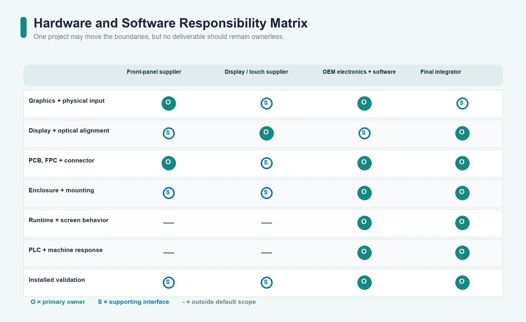
Hardware and Software Responsibility Matrix
Use a matrix before quotation and again before design release.
| Function or deliverable | Front-panel supplier | Display/touch supplier | OEM electronics/software team | Final equipment integrator |
|---|---|---|---|---|
| Printed graphics and physical key layout | Build to approved artwork and drawing | Input where module geometry affects layout | Approve task names and channel map | Confirm installed visibility and access |
| Touch sensor or membrane input layer | Build/integrate as quoted | Supply module data or bonded sensor if applicable | Define controller, thresholds, firmware, diagnostics | Validate with enclosure, environment, and operator |
| Display window and mask | Build to approved stack and tolerances | Supply active/visible area and module drawing | Approve screen safe areas | Validate installed viewing and alignment |
| Display module | Integrate only if explicitly included | Supply controlled module and interface | Drive display and own runtime | Validate thermal, mechanical, and system behavior |
| PCB/FPC and connector | Build or integrate to controlled files | Supply mating interface where applicable | Own schematic/firmware unless quoted otherwise | Confirm harness, grounding, and service access |
| Enclosure gasket and mounting | Supply included parts/features to drawing | Provide module mounting constraints | Define electrical grounding needs | Own enclosure, compression, fasteners, and final ingress result |
| HMI screens, alarms, navigation, permissions | Not included in physical assembly unless explicitly contracted | Usually not included | Own design and validation | Validate in the complete machine |
| PLC, SCADA, safety, and machine response | Outside physical assembly | Outside module scope | Own control logic and communications | Own final system and compliance validation |
The cells can change by project. The purpose is to prevent an unspoken gap.
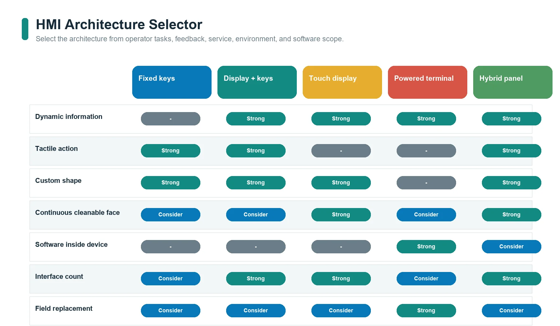
Choose the HMI Architecture by System Boundary
| Architecture | Best fit | Main advantages | Main limitations and questions |
|---|---|---|---|
| Printed panel with discrete keys and indicators | Fixed commands, no graphical display, simple host input | Thin interface, fixed locations, direct tactile options | Limited dynamic information; host must interpret inputs and drive feedback |
| Front panel with display window and physical keys | Dynamic information plus fixed commands | Clear separation between screen and repeated controls | Requires display alignment, bezel control, key/display mapping, and assembly ownership |
| Cover lens or overlay with touch sensor over/around a display | Reconfigurable interface and continuous front surface | Flexible screen layouts, wipe-clean surface, fewer moving key parts | Touch tuning, cover stack, grounding, moisture/glove behavior, feedback, and software become critical |
| Integrated powered HMI terminal | Standard machine platform with processor, communications, runtime, and enclosure | Fewer custom hardware interfaces; established software ecosystem | May constrain shape, branding, lifecycle, repair, cost, and supply; physical custom scope is narrower |
| Hybrid custom panel | Fixed keys, touch/display, indicators, and custom mechanics in one assembly | Assigns each task to the most suitable control type | Highest interface count; responsibility, tolerance, and validation matrix must be explicit |
A custom front-panel assembly is not always the right answer. A standard HMI terminal may be better when software ecosystem, certification, communications, and field replacement matter more than custom shape or branding. A no-display keypad may be better when the machine needs only fixed commands and status indicators.
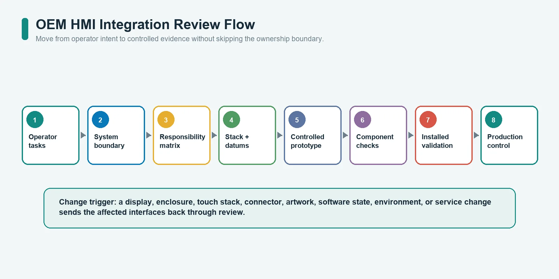
OEM Integration Workflow
This is an integration sequence, not a promise that one supplier owns every step.
1. Define operator tasks and system states
List what the operator must see, decide, enter, confirm, and recover from. Include normal operation, setup, maintenance, cleaning, alarm, disabled, startup, and fault conditions.
2. Draw the system boundary
Create a block diagram identifying:
- front surface;
- keys or touch sensor;
- display;
- circuit and connector;
- controller;
- HMI runtime;
- PLC or machine controller;
- communications;
- enclosure; and
- power and grounding.
Assign an owner to each block and each interface.
3. Freeze mechanical datums and the stack concept
Use controlled drawings for the enclosure, display, touch module, PCB, connector, and front-panel outline. Define active areas, visible areas, bond zones, gasket path, tail route, fasteners, service access, and tolerance ownership.
4. Align artwork, channels, and software names
Create one cross-reference covering:
- printed legend;
- physical target;
- circuit channel;
- connector pin;
- controller input/output;
- software object; and
- displayed or machine response.
5. Review environment and human factors
Document lighting, posture, reach, gloves, cleaning, moisture, contamination, vibration, temperature, expected life, and misuse conditions. Separate component-level requirements from complete-equipment requirements.
6. Build representative prototypes
Prototype the interfaces that carry the most risk. A printed appearance sample cannot validate touch performance. A bare touch sensor cannot validate enclosure grounding or moisture behavior. A display mockup cannot validate connector access.
7. Validate by responsibility level
Use JASPER’s testing and quality-control framework as a starting point for drawing-based visual, dimensional, circuit, actuation, bonding, connector, and assembly checks. The actual HMI plan must be confirmed for the quoted construction. The OEM and integrator still own controller, software, machine, environmental, and final compliance validation unless the contract states otherwise.
Common HMI Panel Specification Mistakes
Quoting only a front-view image
A rendering does not define layers, datums, connector, electronics, mounting, gasket, or test responsibility.
Treating the display, touch sensor, and cover as one unnamed part
They have different active areas, connectors, tolerances, suppliers, and failure modes.
Asking the front-panel supplier to “match the PLC”
The supplier needs an electrical interface, connector map, and responsibility statement. A PLC brand or screenshot does not define the physical HMI.
Selecting input technology before defining the task
A flat touch surface may conflict with gloves, eyes-free operation, or fixed emergency actions. A physical keypad may conflict with dynamic screen functions or a continuous cleanable surface.
Using nominal display size as a tooling dimension
Nominal diagonal size does not control the active area, visible area, module outline, mask, connector, or mounting features.
Ignoring the enclosure until the panel is finished
Adhesive, gasket compression, display support, connector access, grounding, and alignment all depend on the enclosure.
Calling one component “IP65”
Ingress protection is a property of the evaluated enclosure configuration, not a shortcut for one overlay, gasket, or switch layer.
Leaving feedback ownership undefined
The operator may feel a key move but receive no accepted-state indication, or see an LED without knowing whether it means detection, permission, or machine action.
Combining prototype and production criteria
Early samples may explore appearance, fit, touch response, or assembly sequence. Production criteria need controlled drawings, test methods, limits, sampling, and traceability.
OEM Input Checklist for an HMI Hardware Review
Provide:
- Equipment type, installation position, and operator tasks.
- Required commands, displays, indicators, alarms, values, languages, and symbols.
- Preferred architecture: fixed keys, touch, display, hybrid, or standard terminal.
- Front-panel outline, enclosure opening, mounting surfaces, and datum scheme.
- Display manufacturer drawing, active area, visible area, outline, mounting, connector, power, and data interface.
- Touch sensor or key requirements, including gloves, feedback, travel, force, moisture, and tuning ownership where applicable.
- Graphic artwork, color references, finish, window, dead-front, and lighting requirements.
- PCB, FPC, circuit, channel map, pinout, connector, tail or cable route, and electrical limits.
- Controller, firmware, communications, diagnostic, and update ownership.
- Enclosure material, flatness, gasket path, fasteners, adhesive surface, and service strategy.
- Lighting, viewing, cleaning, chemicals, moisture, temperature, vibration, and other real use conditions.
- Prototype purpose, inspection plan, validation matrix, production quantity, traceability, and change-control requirements.
If some inputs are not yet selected, mark them as open and assign an owner and
decision date. Do not hide an unresolved interface behind supplier to recommend.
Frequently Asked Questions
What is the difference between an HMI panel and an HMI system?
An HMI panel is the physical operator-facing hardware or terminal. An HMI system also includes runtime software, screen behavior, controller interfaces, data, communications, permissions, alarms, and machine response. Define the boundary in the BOM and responsibility matrix.
Is an HMI panel the same as a touchscreen?
No. A touchscreen is one possible input component. An HMI panel may use membrane keys, silicone keys, switches, indicators, a display without touch, touch without a display, or a hybrid combination.
Is the display window the same as the display?
No. The window is the viewing region in the front surface. The display module generates the image. Their visible areas, active areas, outlines, tolerances, and mounting details must be aligned.
Does JASPER provide PLC programming or SCADA software?
The confirmed scope of this Resource is JASPER’s physical HMI front-panel assembly. It does not claim PLC programming, SCADA software, industrial PC supply, complete control-cabinet engineering, or final machine validation.
Can a custom HMI panel include a PCB and connector?
It can when those items are explicitly included in the drawing and quotation. The project must state whether the PCB is passive routing or an active controller, who owns the schematic and firmware, and which electrical and functional tests are required.
Does a sealed front panel make the complete machine IP rated?
No. A front panel can contribute to an ingress-protection design, but the result depends on the complete enclosure, seams, fasteners, gasket compression, connectors, openings, and assembly. The final configuration requires appropriate evaluation and testing.
What should be reviewed before HMI tooling?
Review operator tasks, architecture, stack cross-section, enclosure and display datums, touch or key behavior, artwork, circuit and connector map, mounting and gasket, environment, responsibility matrix, prototype purpose, and acceptance criteria.
Review the Hardware Stack Before Tooling
Send the enclosure drawing, display/module data, artwork, key or touch map, circuit and connector requirements, mounting concept, environment, and responsibility matrix through the JASPER contact form. The first review should identify what belongs inside the physical HMI assembly, what remains with the electronics and software team, and which interfaces still need an owner.
Sources
- JASPER Electronics, “Custom HMI Assembly for OEM Front Panels and Operator Interfaces.” https://www.jasperele.com/products/hmi-assembly/
- JASPER Electronics, “Industrial Control Interfaces.” https://www.jasperele.com/applications/industrial-control/
- JASPER Electronics, “Membrane Switch Testing and Quality Control.” https://www.jasperele.com/quality/testing/
- International Society of Automation, “ISA101, Human-Machine Interfaces.” https://www.isa.org/standards-and-publications/isa-standards/isa-standards-committees/isa101
- International Organization for Standardization, “ISO 9241-210:2019, Ergonomics of human-system interaction – Part 210: Human-centred design for interactive systems.” https://www.iso.org/standard/77520.html
- International Electrotechnical Commission, “IEC 60529:1989+AMD1:1999+AMD2:2013 CSV, Degrees of protection provided by enclosures (IP Code).” https://webstore.iec.ch/en/publication/2452
- Microchip Technology, “Capacitive Touch Sensor Design Guide AN2934.” https://onlinedocs.microchip.com/oxy/GUID-A8A0085D-58D1-4E41-A07D-B93BFDE11AFE-en-US-4/GUID-80CF1688-09E6-46D2-B2C6-44743EA74277.html