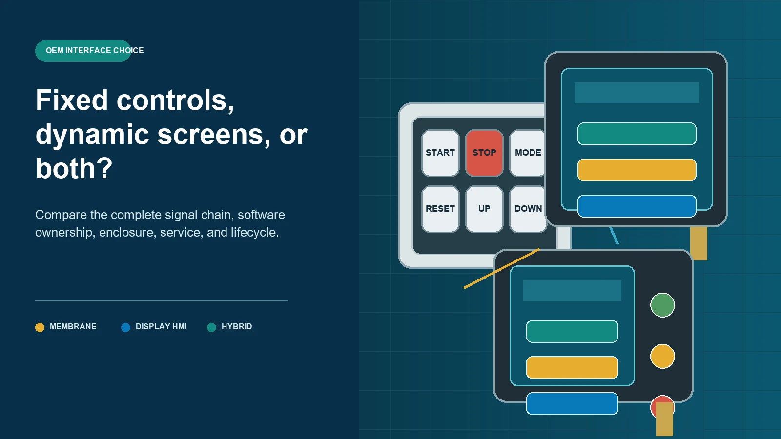
Choose an HMI panel when the product must present changing information, menus,
recipes, diagnostics, multiple languages, or context-dependent controls. Choose a
membrane switch panel when commands and indicators are mostly fixed, physical key
location or tactile feedback matters, and the host electronics can interpret a
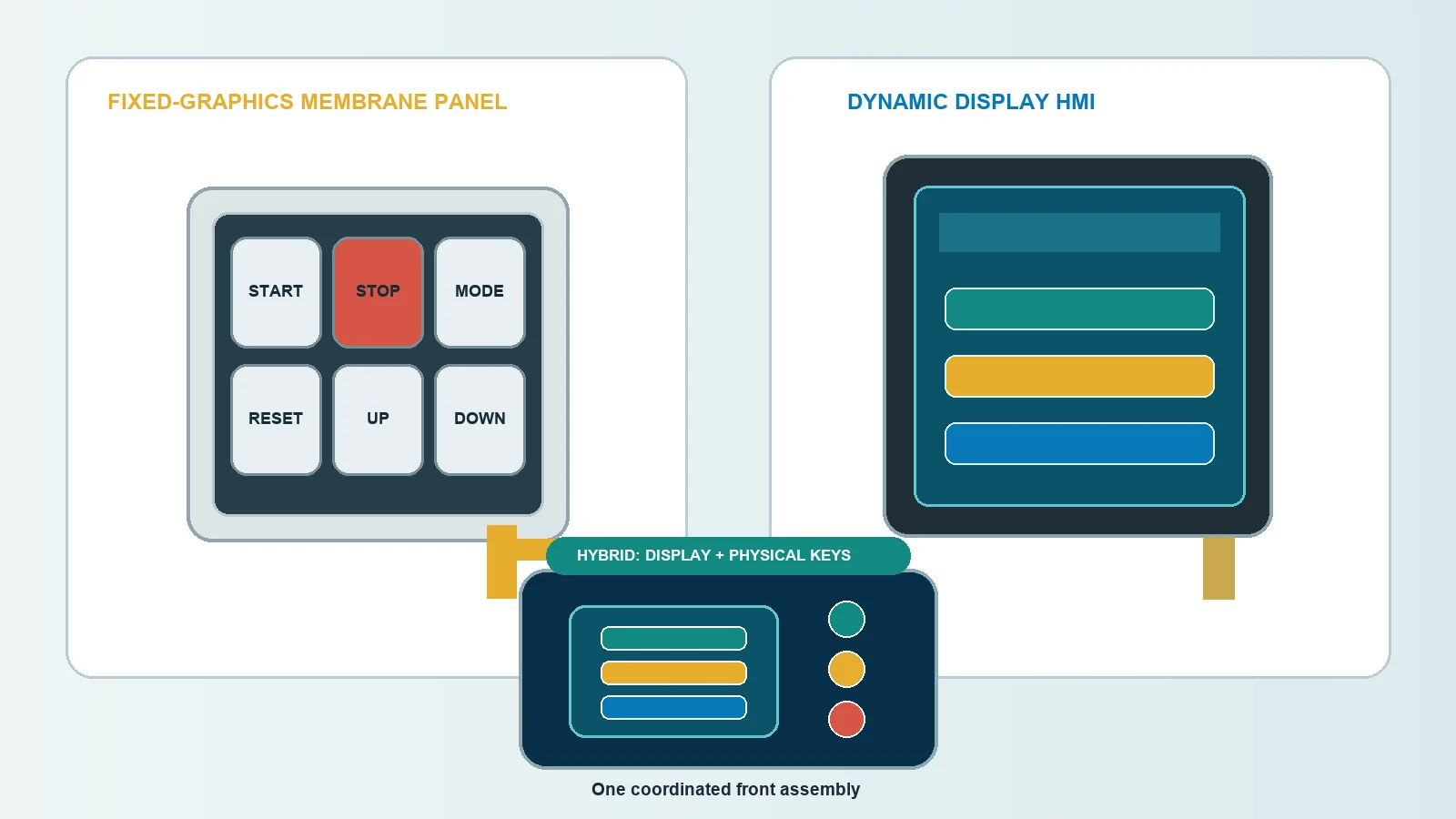
simple switch circuit. The categories can overlap: an HMI assembly may include a
display plus membrane keys, and a membrane panel may include display windows and
LED indicators. The real decision is not touch versus buttons. It is how much
information, software, hardware, enclosure depth, service, validation, and change
the product must support.
JASPER’s custom HMI assembly
and custom membrane switch
panel
pages represent two physical interface routes. The OEM still needs to define the
operator tasks, display ownership, control electronics, software, connector,
mounting, environment, service model, and final system validation before either
route can be selected.
- HMI Panel and Membrane Switch Panel Are Not Exact Opposites
- Quick Architecture Decision
- Start With the Information Model
- A fixed information model
- A dynamic information model
- Mixed information
- Compare Complete Signal Chains
- Membrane switch panel chain
- Display-based HMI chain
- Tactile Feedback and Eyes-Off Operation
- Display Need and Information Density
- Hardware and Software Dependency
- Enclosure Depth, Mounting, and Packaging
- Sealing, Cleaning, and Environmental Boundaries
- Product Lifecycle and Change Management
- Membrane switch panel lifecycle
- Display-based HMI lifecycle
- Lifecycle questions for both
- Serviceability and Failure Isolation
- Cost Structure: Compare Total Integration, Not One Unit Price
- Validation Burden by Architecture
- Membrane switch panel
- Display-based HMI panel
- Hybrid interface
- Architecture Patterns
- Pattern 1: Fixed membrane control panel
- Pattern 2: Membrane panel around a separate display
- Pattern 3: Custom touch-display HMI assembly
- Pattern 4: Standard powered HMI terminal
- Pattern 5: Hybrid custom HMI
- A Practical Selection Scorecard
- Representative Decision Patterns
- Stable machine controls with a few status indicators
- Recipe-driven process equipment
- Laboratory instrument with changing results and repeated navigation
- Standard industrial machine platform
- When a Membrane Switch Panel Is the Wrong Fit
- When a Display-Based HMI Is the Wrong Fit
- Prototype the Decision, Not Just the Appearance
- Common Comparison Mistakes
- Comparing a touch sensor with a complete membrane panel
- Assuming every HMI is a touchscreen
- Assuming every membrane panel has no display
- Comparing only unit price
- Treating fixed graphics as a weakness in every product
- Treating software flexibility as free
- Claiming one architecture is sealed by default
- Moving all controls onto a screen without task review
- Leaving the replaceable unit undefined
- OEM Input Checklist
- Select the Architecture Before Freezing the Front Panel
- Sources
HMI Panel and Membrane Switch Panel Are Not Exact Opposites
A membrane switch panel is a physical input and indication assembly. It commonly
uses printed fixed graphics, discrete key zones, a flexible circuit, optional
tactile domes, display windows, indicators, a connector tail, and rear mounting
adhesive.
An HMI panel is a broader operator-interface architecture. It may be:
- a display with touch input;
- a display with separate physical keys;
- a custom front-panel assembly around customer electronics;
- a display, PCB, keys, indicators, and connector in one assembly; or
- a complete powered terminal with processor, runtime, communications, and
enclosure.
The overlap matters.
Membrane switch panel
    fixed legends + discrete keys + circuit + indicators + windows

Display-based HMI panel
    display + input + controller + runtime + communications

Hybrid HMI assembly
    display + membrane keys + indicators + PCB/FPC + connector + enclosure interface
Do not compare a complete powered HMI terminal with only the top film of a
membrane switch. Compare complete architectures at the same system boundary.
Use the HMI panel hardware and software boundary
guide when the
project team still needs to separate the front surface, input, display, circuit,
connector, enclosure, runtime, PLC, and final machine responsibilities.
Quick Architecture Decision
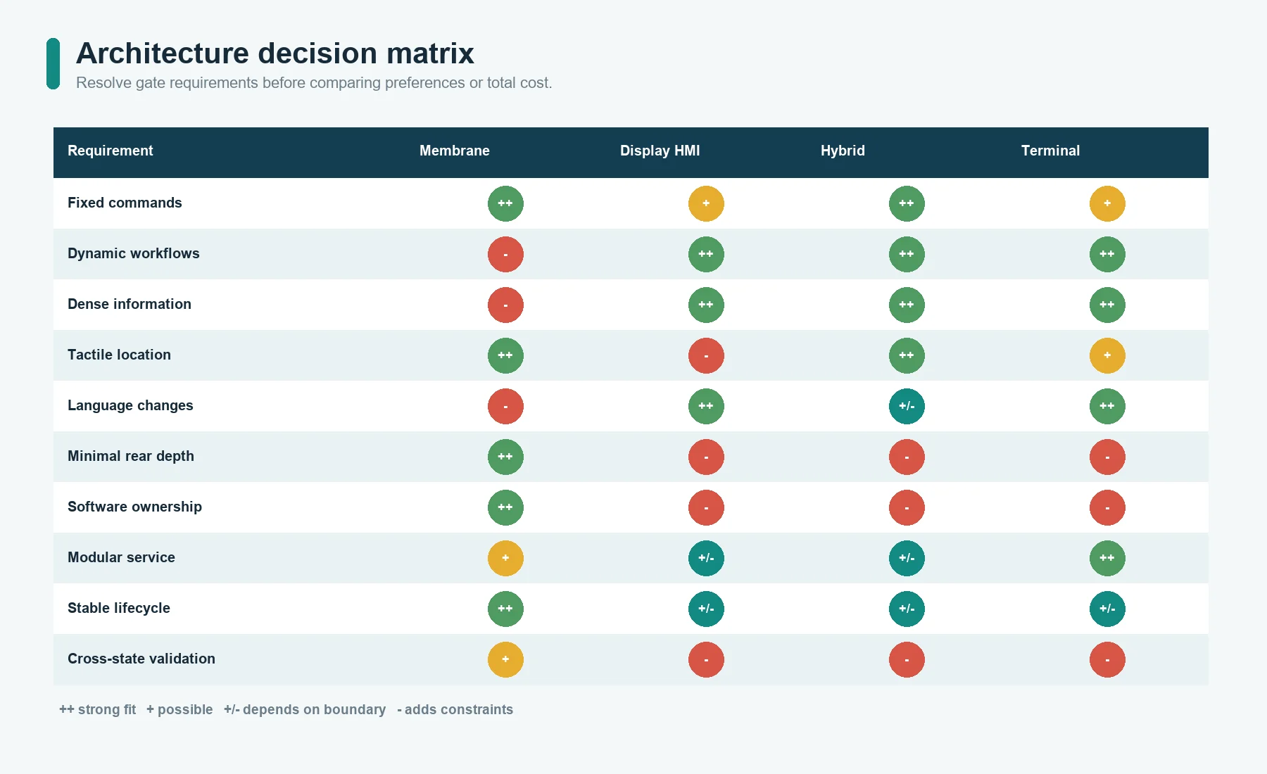
| Product requirement | Membrane switch panel | Display-based HMI panel | Hybrid interface |
|---|---|---|---|
| Fixed commands and fixed legends | Strong fit | Possible but may add unnecessary system layers | Useful if a small display is still needed |
| Changing menus, values, recipes, or workflows | Limited without a separate display | Strong fit | Strong fit when fixed keys remain useful |
| Physical key location or tactile snap | Direct option | Requires separate keys or another feedback method | Direct option beside the display |
| Frequent language or label changes | Requires new artwork or an alternate label strategy | Screen content can change in software | Fixed critical labels plus translated screen content |
| Dense diagnostics or trend information | Poor fit as a stand-alone panel | Strong fit | Strong fit |
| Simple discrete host inputs | Strong fit | May require controller and communication integration | Can separate fixed inputs from display functions |
| Minimal enclosure depth and electronics | Often favorable, depending on stack | Display, board, cable, and mounting depth must be allowed | More depth and interfaces than a stand-alone panel |
| Field software updates | Usually not part of the panel | Often part of the HMI system | Applies to the display/controller portion |
| Clear eyes-off key location | Possible with spacing, embossing, domes, or raised features | Flat touch targets may require visual attention | Physical keys can cover repeated actions |
| Modular terminal replacement | Less common for bonded custom panels | Possible with a standard or removable terminal | Depends on how the custom front and terminal are separated |
No row decides the architecture alone. The team should first identify which
requirements are gates and which are preferences.
Start With the Information Model
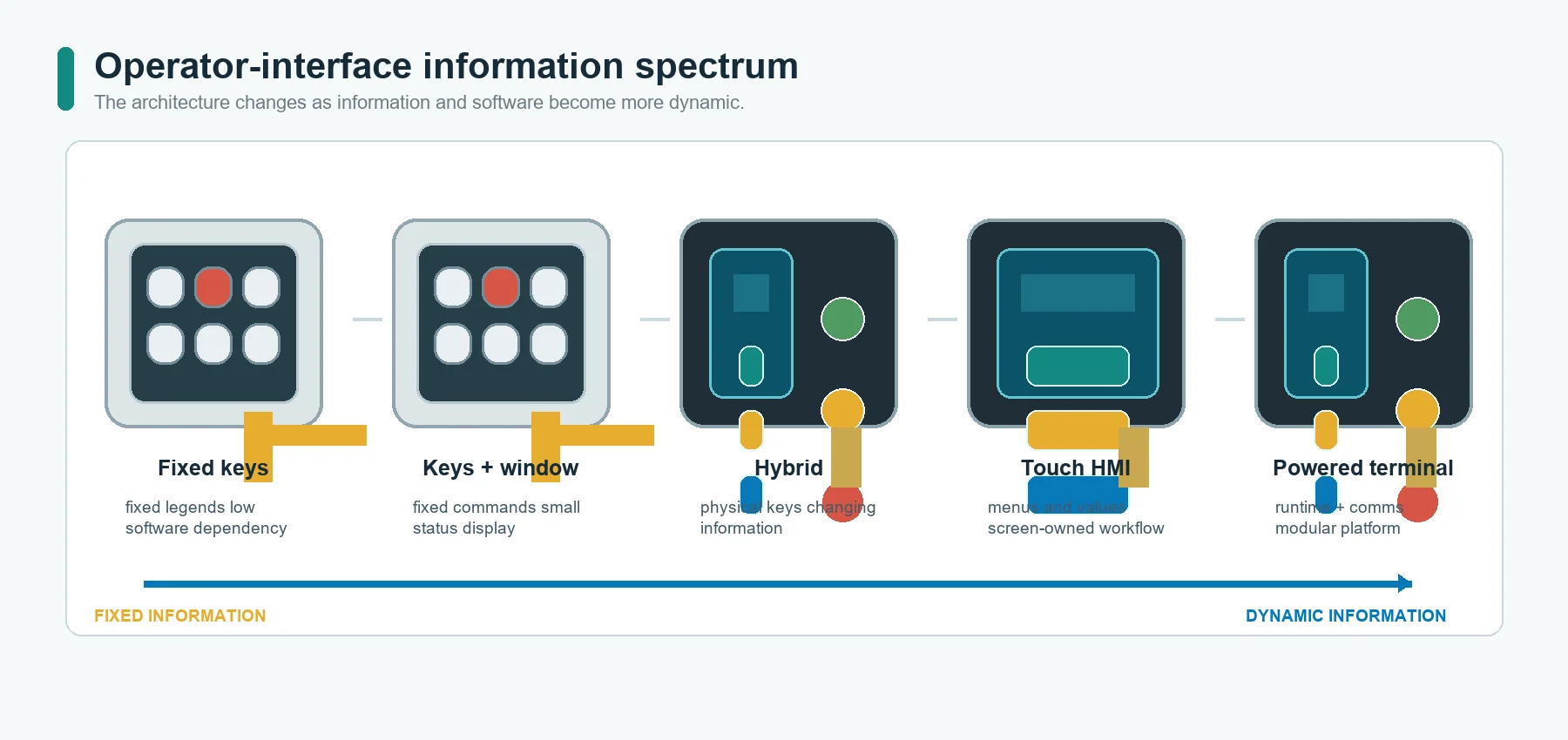
The most important question is not How many buttons are there? It is Does the information and command set remain fixed?
A fixed information model
A membrane switch panel is a natural candidate when:
- the command names remain stable;
- each key keeps the same function;
- status can be communicated by fixed indicators, a small display window, or the
machine itself; - the host needs discrete contact or matrix inputs;
- the operator benefits from fixed physical landmarks; and
- product updates do not regularly change the workflow.
Examples include equipment with a stable set of start, stop, mode, reset, speed,
navigation, or set-point keys. The exact architecture still depends on the system,
but the interface does not need to redraw itself for every state.
A dynamic information model
A display-based HMI becomes more useful when:
- controls change by operating mode;
- the operator must browse menus or records;
- the product shows trends, diagrams, alarms, or detailed diagnostics;
- values require direct entry;
- different users receive different functions;
- multiple languages must be available without replacing the front artwork; or
- future releases may add workflows through software.
ISA101 includes screen navigation, graphics, dynamic elements, alarming, security,
and interfaces to programs and databases within the broader manufacturing HMI
discipline.[6] These functions are not created by a cover lens or display alone.
They require screen design, runtime behavior, data, communications, controller
integration, and validation.
Mixed information
Many products have both:
- repeated fixed actions that benefit from physical keys; and
- changing information that belongs on a display.
That is the case for a hybrid HMI. The display handles context, instructions,
values, and diagnostics. Membrane keys handle stable actions, navigation,
acknowledgement, or other repeated inputs. The split must be based on operator
tasks, not visual symmetry.
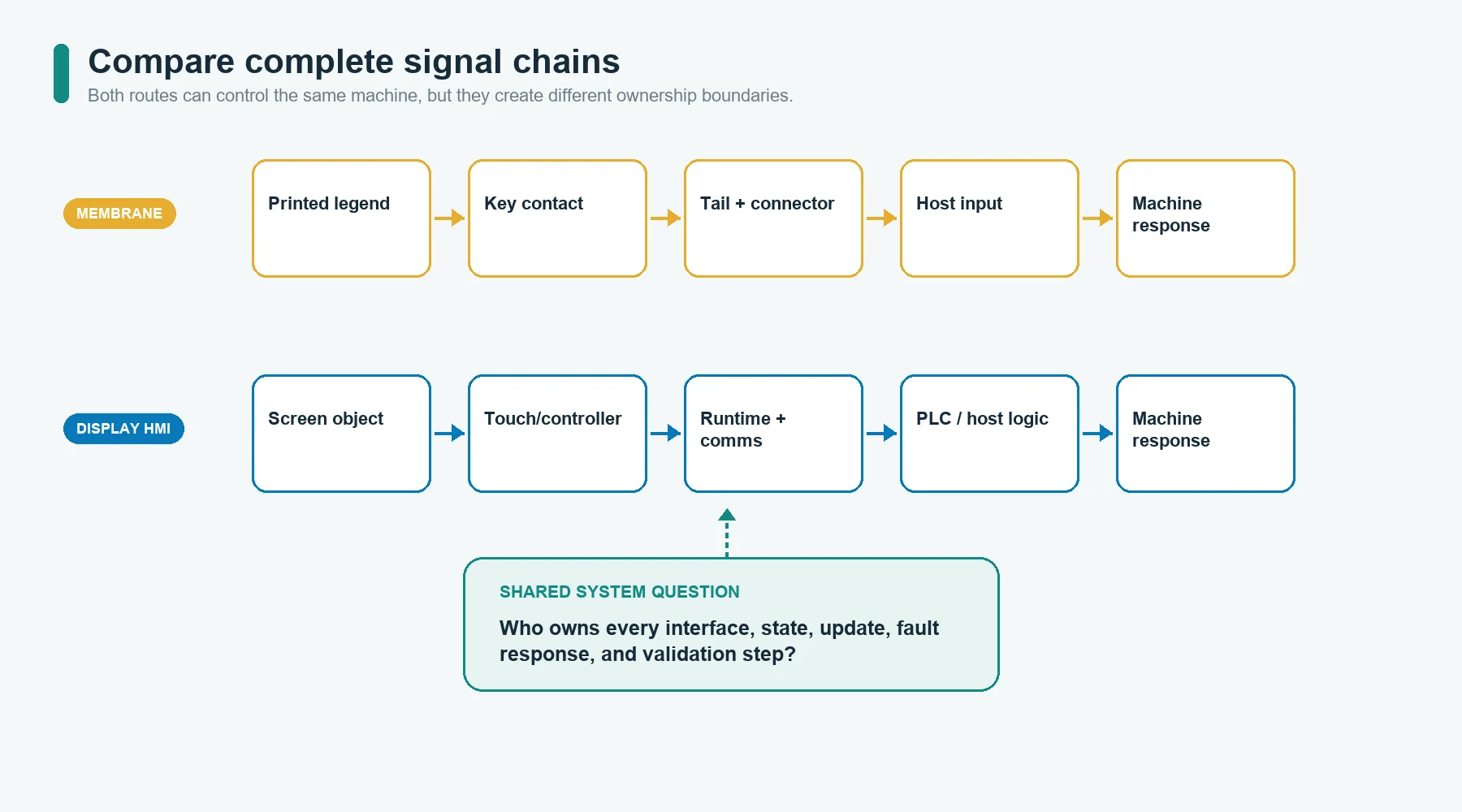
Compare Complete Signal Chains
A membrane switch key and a displayed touch target create different engineering
chains.
Membrane switch panel chain
Printed legend
    -> physical key zone
    -> contact closure or matrix state
    -> tail and connector
    -> host input
    -> machine or display response
Display-based HMI chain
Screen object
    -> touch or key input
    -> sensor/controller
    -> HMI runtime
    -> communication or host input
    -> PLC or machine logic
    -> screen and machine response
The second chain is not automatically worse. It supports functions that the first
chain cannot provide by itself. It also creates more interfaces to own, document,
update, diagnose, and validate.
Tactile Feedback and Eyes-Off Operation
A membrane switch panel can provide:
- tactile snap through a dome;
- non-tactile contact;
- embossed or raised key location;
- fixed spacing;
- printed or backlit legends; and
- local LED feedback.
This can help an operator locate repeated controls by position and feel. The
result still depends on key size, spacing, support, actuation behavior, glove use,
surface geometry, and the surrounding enclosure.
A flat touchscreen does not provide key travel by itself. Feedback can come from:
- a visible state change;
- an audible signal;
- vibration or haptic actuation;
- a separate physical key; or
- machine response.
Do not treat tactile snap as proof that a command was accepted. It confirms a
physical event at the key. The controller and machine still decide whether the
command is valid and executed.
The industrial-control case study on JASPER’s site describes why key structure,
legend durability, tail routing, connector matching, and enclosure
fit
must be reviewed together for a machine interface. It is an application framework,
not a universal requirement or a claimed result for every panel.
Display Need and Information Density
A membrane panel can include:
- transparent or tinted display windows;
- printed masks;
- LED indicators;
- dead-front icons;
- simple segmented displays supplied by the OEM; and
- labels around a separate screen.
It can therefore support a display without becoming a complete software HMI
terminal.
A display-based HMI is more suitable when the screen itself carries a large part of
the operator workflow. The project then needs to define:
- display active and visible areas;
- graphics and safe regions;
- touch active area;
- screen hierarchy;
- data ownership;
- alarm and status behavior;
- user roles;
- controller and communication interfaces;
- startup, fault, and update states; and
- validation of every relevant state and transition.
The display may reduce the number of printed legends, but it does not eliminate
front-surface, touch, connector, enclosure, feedback, or service requirements.
Hardware and Software Dependency
| Dependency | Membrane switch panel | Display-based HMI panel |
|---|---|---|
| Printed artwork | Defines most visible labels and key locations | May define bezel, branding, fixed warnings, and off-screen controls |
| Circuit | Usually passive contacts, matrix, LEDs, or project-specific circuitry | Touch sensor, display interface, controller, power, communications, and optional keys |
| Firmware | Often belongs to the host, not the passive panel | May be required for touch, display, communications, boot, diagnostics, and updates |
| Runtime/screens | Not part of a stand-alone membrane panel | Core part of the complete HMI system |
| Host integration | Discrete inputs, matrix scanning, indicators, or simple display | Data model, protocol, permissions, state synchronization, and fault behavior |
| Update process | Artwork or hardware revision | Software, firmware, content, artwork, hardware, or combinations |
| Cybersecurity and access | Usually handled by the host system | Must be addressed where the HMI stores, communicates, or controls data |
JASPER’s confirmed scope in this Blog is physical interface hardware and assembly.
It does not claim PLC programming, SCADA configuration, HMI runtime development,
industrial PC supply, cybersecurity validation, or complete control-cabinet
engineering.
Enclosure Depth, Mounting, and Packaging
A thin membrane panel can bond to an enclosure surface, but the complete design may
still include:
- tactile domes;
- spacer layers;
- backlighting;
- display windows;
- PCB support;
- connector hardware;
- gasket or bezel features; and
- cable clearance.
A display-based HMI usually needs additional depth for the display module,
controller, connector, cable bend, support, thermal path, and service access. A
standard terminal may also require rear mounting clips or fasteners.
Do not compare only front-face thickness. Compare the complete installation
envelope:
- front projection;
- enclosure cutout;
- rear depth;
- cable and connector access;
- fastener or adhesive area;
- display and PCB support;
- assembly sequence; and
- removal path.
A visually compact HMI can still conflict with an internal bracket, harness, or
service tool.
Sealing, Cleaning, and Environmental Boundaries
Both architectures can contribute to a cleanable and sealed front. Neither earns
an ingress rating by category name.
A membrane panel may use a continuous printed surface, rear adhesive, gasket
details, sealed key zones, and controlled tail exits. Risks can still occur at:
- the panel perimeter;
- display window;
- LED or light-guide opening;
- tail exit;
- connector;
- enclosure seam;
- fastener; and
- damaged or contaminated bond area.
A display-based HMI may use a cover lens, bonded touch sensor, bezel, gasket,
housing, connector seals, and rear enclosure. Risks can still occur at the same
interfaces, plus service joints and display-module boundaries.
IEC 60529 classifies degrees of protection provided by enclosures.[8] The final
claim therefore depends on the evaluated enclosure configuration, mounting,
compression, openings, connectors, and assembly process. A loose membrane switch,
cover lens, or gasket does not transfer its assumed protection to the whole
machine.
Cleaning requirements should name actual agents, concentration or use method where
known, frequency, temperature, abrasion, and whether the product is wiped,
sprayed, rinsed, or exposed during operation. Wipe-clean is not a material
specification.
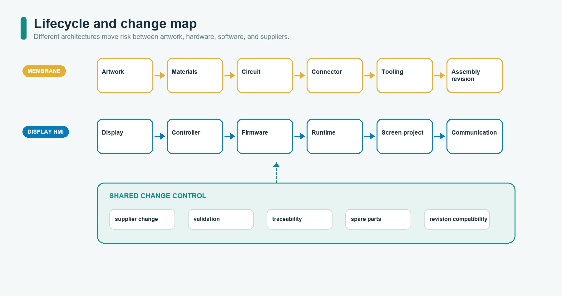
Product Lifecycle and Change Management
The architectures age differently.
Membrane switch panel lifecycle
Potential change drivers include:
- graphic revision;
- language change;
- key-function change;
- dome or spacer change;
- circuit or pinout change;
- adhesive or surface change;
- LED or backlight change;
- tail, connector, or enclosure revision; and
- material or process source change.
A stable command set can remain useful without a screen-software lifecycle.
Changing fixed legends or key functions usually requires controlled artwork or
hardware revision.
Display-based HMI lifecycle
Potential change drivers include:
- display-module availability;
- touch-controller availability;
- processor or memory revision;
- operating system or runtime support;
- communication or security requirements;
- screen-content revision;
- firmware update;
- connector or cable change;
- graphics or localization; and
- enclosure or thermal revision.
Software can change the visible interface without replacing the front artwork,
but the project must manage versioning, regression, update delivery, and support.
Lifecycle questions for both
Ask:
- How long must the product platform remain available?
- Which parts can be substituted without tooling or software change?
- Who owns end-of-life monitoring?
- Is a display, controller, artwork, or material change a form-fit-function change?
- What evidence must be repeated after a change?
- Must field units remain visually and functionally identical?
- How are spare parts and revisions identified?
Do not assume that no software update means no lifecycle risk, or that a
software-defined interface can change without revalidation.
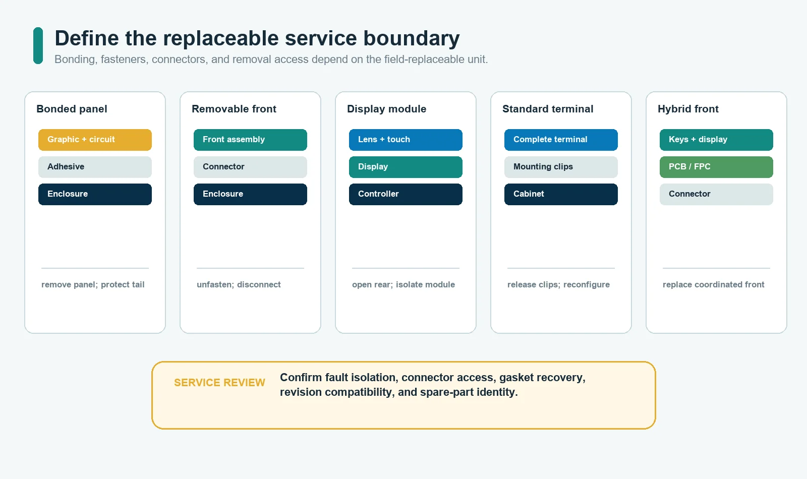
Serviceability and Failure Isolation
| Service question | Membrane switch panel | Display-based HMI panel |
|---|---|---|
| Typical replaceable boundary | Bonded panel, panel plus bezel, or front assembly | Display/touch module, controller, complete terminal, or custom assembly |
| Common fault domains to isolate | Key contact, circuit, tail, connector, LED, artwork, bond, enclosure fit | Display, backlight, touch, controller, cable, power, runtime, communication, enclosure |
| Field diagnostic need | Continuity, key state, connector, indicator, host input | Power, display, touch, software state, communication, host data, connector |
| Revision compatibility | Artwork, circuit, connector, mechanical fit | Hardware, firmware, runtime, protocol, screen project, mechanical fit |
| Removal risk | Adhesive damage, overlay damage, tail access, bezel removal | Glass damage, cable access, fasteners, gasket, firmware configuration |
Define the replaceable unit before finalizing adhesive, gasket, fastener, connector,
display mounting, and test access.
A permanently bonded front can support a clean surface but make field replacement
more difficult. A removable terminal can simplify module replacement but may
create a larger cutout, bezel, or rear-depth requirement. There is no universal
service winner.
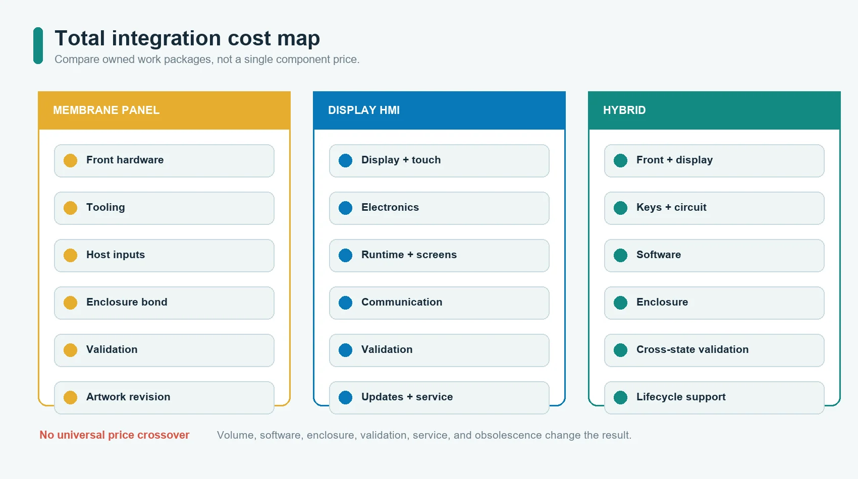
Cost Structure: Compare Total Integration, Not One Unit Price
This Blog does not assign a universal price crossover. Actual cost depends on
dimensions, layers, display, electronics, tooling, volume, suppliers, software,
testing, enclosure, certification, and service.
| Cost element | Membrane switch panel | Display-based HMI panel |
|---|---|---|
| Front artwork and tooling | Artwork, printing, cutting, domes, circuit, adhesive, fixtures | Cover lens or overlay, printing, touch, bezel, mechanical fixtures |
| Electronics | Host scanning, LEDs, optional PCB/display | Display, touch controller, processor or interface board, power, communications |
| Software | Host input logic and indicators | Screen project, runtime, data mapping, localization, updates, regression |
| Mechanical integration | Bond area, window, tail, connector, enclosure support | Cutout, display support, bezel/gasket, rear depth, cable, thermal and service access |
| Validation | Visual, dimensional, circuit, actuation, bond, window, environment | Hardware checks plus display, touch, software states, communications, updates |
| Change cost | New artwork, tooling, circuit, or assembly revision | Software/firmware revision, hardware change, module substitution, or combinations |
| Field support | Panel or front-assembly replacement | Module, terminal, software, cable, or configuration support |
For a stable interface, added display and software layers may not create useful
value. For a changing workflow, forcing all information into fixed labels and keys
can create a confusing panel, extra indicators, or repeated hardware revisions.
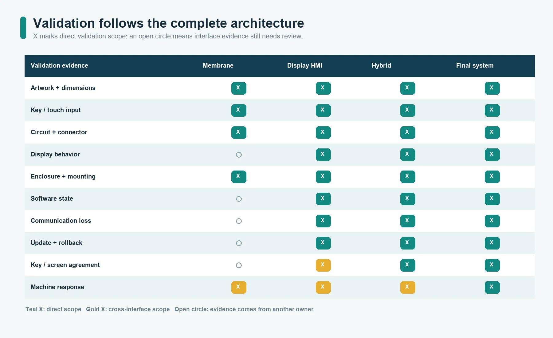
Validation Burden by Architecture
Membrane switch panel
Project-specific checks may include:
- appearance and artwork;
- color and surface;
- dimensions and registration;
- key actuation and release;
- continuity, short/open, and pinout;
- LED or backlight function;
- display-window alignment;
- adhesive or gasket fit;
- tail and connector;
- installed enclosure fit;
- cleaning and environmental exposure; and
- production traceability.
Display-based HMI panel
In addition to relevant physical checks, the system may need:
- display function and visual acceptance;
- touch mapping and edge behavior;
- grounding and shielding review;
- startup and shutdown;
- power interruption and recovery;
- screen state and navigation;
- data validity and stale-data behavior;
- communication loss;
- user access and configuration;
- firmware and software version control;
- update and rollback behavior;
- localization;
- diagnostics; and
- full machine response.
Hybrid interface
The hybrid must also prove that screen objects, physical keys, indicators, and
machine states agree. A physical key labelled RESET, for example, should not
create an ambiguous result when the current screen disables or redefines the
action.
ISO 9241-210 treats human-centred design as a lifecycle activity and recognizes
that both hardware and software affect the interaction.[7] Validation should
therefore follow the complete task and state chain, not stop after the front panel
passes inspection.
Architecture Patterns
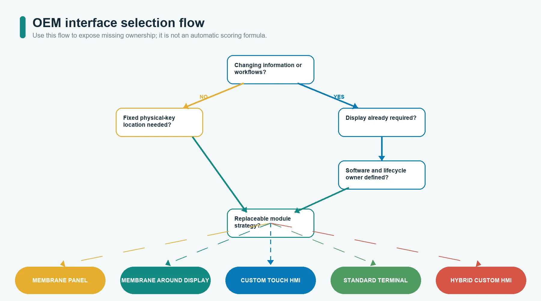
Pattern 1: Fixed membrane control panel
Use when:
- command set is stable;
- no rich display is required;
- the host accepts discrete or matrix inputs;
- fixed key location is valuable; and
- product updates rarely change the operator workflow.
Main risks:
crowded legends, poor key spacing, connector mismatch, unsupported tactile feel,
and artwork revisions after tooling.
Pattern 2: Membrane panel around a separate display
Use when:
- the display presents values or status;
- physical keys handle navigation or commands;
- the OEM owns the display and software; and
- the front surface needs one coordinated window, key, indicator, and mounting
design.
Main risks:
display-window alignment, key-to-screen mapping, enclosure tolerances, and separate
supplier responsibilities.
Pattern 3: Custom touch-display HMI assembly
Use when:
- screen content changes by mode;
- data entry, menus, graphics, or localization are important;
- a continuous front surface is preferred; and
- the OEM can own controller, runtime, communication, and validation.
Main risks:
touch-cover stack, grounding, moisture/glove behavior, display availability,
software states, and service access.
Microchip’s touch-sensor design guidance treats touch-cover effects and shielding
as sensor-design inputs.[9] A cosmetic cover or enclosure change can therefore
affect touch performance and require review or retuning.
Pattern 4: Standard powered HMI terminal
Use when:
- a standard runtime and communication platform fits the machine;
- modular field replacement is valuable;
- custom front shape and minimal depth are less important; and
- the OEM accepts the terminal vendor’s lifecycle and software environment.
Main risks:
supplier dependency, product obsolescence, software migration, bezel/cutout
constraints, and limited custom appearance.
Pattern 5: Hybrid custom HMI
Use when:
- changing information belongs on a display;
- repeated actions benefit from physical keys;
- local indicators or backlighting improve use; and
- one coordinated front assembly can reduce fit and alignment conflicts.
Main risks:
the hybrid inherits physical, display, controller, software, and cross-state
validation work. Hybrid is not automatically the simpler compromise.
A Practical Selection Scorecard
For each requirement, mark it as:
Gate: architecture cannot be approved without it;Weighted: important, but can trade against another requirement; orPreference: desirable but not decision-driving.
Then record evidence, not just a score.
| Question | Evidence to collect | Likely direction |
|---|---|---|
| Must controls or labels change by state? | Screen and command-state list | HMI or hybrid |
| Must the operator read trends, diagrams, records, or detailed alarms? | Information inventory and screen mockup | HMI |
| Must repeated keys be located by feel or fixed position? | Task observation, glove, posture, key-frequency data | Membrane or hybrid |
| Can the host accept simple discrete inputs? | Schematic, input map, scan method | Membrane possible |
| Is software update and long-term support available? | Owner, toolchain, version and support plan | HMI possible |
| Is rear depth tightly constrained? | Enclosure section and cable envelope | Often membrane, but verify full stack |
| Must the front be replaced as a field module? | Service procedure and access study | Standard HMI or modular hybrid may help |
| Will labels or languages change during product life? | Localization and revision plan | HMI or hybrid |
| Is a display already required for another function? | Controlled display drawing and software scope | HMI or display-plus-membrane |
| Is the interface expected to remain stable for the platform life? | Product roadmap and change history | Membrane may reduce software dependency |
Do not total the last column mechanically. Resolve every gate first, then compare
the complete BOM, software, validation, service, and lifecycle plan.
Representative Decision Patterns
These are architecture examples, not customer claims.
Stable machine controls with a few status indicators
A membrane switch panel may fit when the equipment has a fixed operating sequence,
stable key labels, a few indicator states, and a host controller that already
handles the logic.
Recipe-driven process equipment
A display-based HMI may fit when operators select recipes, enter values, review
alarms, and access maintenance pages. Physical keys can remain for frequent or
fixed commands.
Laboratory instrument with changing results and repeated navigation
A hybrid interface may fit when the display shows measurements and records while a
small set of fixed keys handles navigation or acknowledgement.
Standard industrial machine platform
A standard terminal may fit when the OEM values a known runtime, communication
support, and replaceable module more than a custom front shape.
When a Membrane Switch Panel Is the Wrong Fit
Reconsider a stand-alone membrane panel when:
- the interface needs many changing controls;
- operators must review dense or graphical information;
- language changes would create many artwork variants;
- future functions depend on flexible screen workflows;
- the panel would become crowded with labels and indicators; or
- the host cannot accept the required input and feedback architecture.
Adding more printed keys is not a substitute for an information architecture.
When a Display-Based HMI Is the Wrong Fit
Reconsider a display-based HMI when:
- the task has only a few stable commands;
- the display adds no useful information;
- the project lacks software, runtime, version, and support ownership;
- enclosure depth, power, thermal, or service constraints are unresolved;
- the product cannot manage display or controller obsolescence;
- operators require fixed physical landmarks that the proposed interface does not
provide; or - validation effort is not matched to the software and communication complexity.
A screen is not an automatic upgrade.
Prototype the Decision, Not Just the Appearance
Use JASPER’s membrane switch prototyping
capability as a starting
point for physical sample planning. The actual prototype stages must match the
architecture.
Possible prototype questions:
- Can the operator complete the task with the proposed key and screen split?
- Are fixed keys large, spaced, supported, and located correctly?
- Is the display readable through the real window and enclosure?
- Does touch work through the real cover and installed stack?
- Do the connector, tail, cable, and rear depth fit?
- Can the panel or terminal be assembled and removed?
- Do key, indicator, screen, controller, and machine states agree?
- Which parts of the sample are appearance-only and which are production
representative?
An appearance mockup can answer layout questions. It cannot validate electronics,
touch behavior, sealing, software, communication, or lifecycle.
Common Comparison Mistakes
Comparing a touch sensor with a complete membrane panel
A touch sensor is one input component. Compare complete front-panel and system
architectures.
Assuming every HMI is a touchscreen
An HMI can use physical keys, touch, display-only information, or a hybrid.
Assuming every membrane panel has no display
A membrane panel can integrate display windows, indicators, and controls around a
separate display.
Comparing only unit price
Include display, electronics, software, tooling, enclosure, validation, updates,
service, and obsolescence.
Treating fixed graphics as a weakness in every product
Fixed legends can be appropriate when the task is stable and clear. They become a
constraint when workflows or languages change.
Treating software flexibility as free
Screen changes require ownership, version control, regression, release, and
support.
Claiming one architecture is sealed by default
The complete enclosure and assembly configuration determines ingress protection.
Moving all controls onto a screen without task review
The screen should own functions that benefit from context and change. Physical
controls may remain appropriate for repeated, located, or independent actions.
Leaving the replaceable unit undefined
Bonding, fasteners, connectors, gaskets, and service access depend on what will be
replaced.
OEM Input Checklist
Provide:
- Equipment type, user, posture, gloves, lighting, and operating environment.
- Complete command, status, alarm, value, and information inventory.
- Which controls and labels are fixed, conditional, or expected to change.
- Need for display graphics, data entry, recipes, trends, records, languages, or
user roles. - Need for tactile feedback, key travel, fixed location, audible, visual, or
haptic feedback. - Enclosure outline, cutout, mounting surface, rear depth, cable access, and
service route. - Display and touch module drawings, active areas, connectors, power, and
ownership. - Circuit, PCB/FPC, pinout, connector, host input, communication, grounding, and
shielding requirements. - Runtime, PLC, software, firmware, localization, update, diagnostic, and
cybersecurity ownership. - Cleaning, moisture, contaminants, temperature, vibration, lifecycle, and
storage requirements. - Replaceable unit, spare-part plan, product life, obsolescence owner, and
approved substitutions. - Prototype purpose, validation matrix, acceptance criteria, volume, traceability,
and change-control process.
If the architecture is still open, provide both the task list and system block
diagram. A supplier cannot select the interface from a front rendering alone.
Frequently Asked Questions
Is a membrane switch panel an HMI?
Yes. It is a form of human-machine interface when it lets an operator give
commands or read status. In this comparison, display-based HMI panel refers to
an architecture with dynamic screen content, while membrane switch panel
refers to a fixed-graphics physical input panel.
Can an HMI panel use membrane switches?
Yes. A hybrid HMI can combine a display with membrane keys, indicators, a PCB/FPC,
connector, and custom front surface.
Which is better for gloves?
Do not decide by category alone. Define glove type, fit, moisture, operator
posture, key force or touch tuning, feedback, and environment. Physical raised or
tactile keys may make location easier, while a touch system requires
project-specific sensor, cover, controller, and tuning validation.
Which architecture is cheaper?
There is no universal answer. Compare complete front hardware, display,
electronics, software, tooling, enclosure, validation, updates, service, volume,
and lifecycle. A unit-price comparison leaves out major ownership costs.
Can a membrane switch panel include a display window?
Yes. The panel can include clear or tinted windows, printed masks, indicators, and
keys around a separate display. The OEM must control the display drawing,
alignment, mounting, connector, and software.
Which architecture lasts longer?
The answer depends on the failure definition and complete system. A membrane panel
has mechanical, graphic, circuit, adhesive, connector, and enclosure risks. A
display HMI adds display, backlight, touch, controller, software, communication,
and obsolescence risks. Define the use profile and acceptance criteria instead of
using one universal lifetime number.
Should every new product use a touchscreen HMI?
No. Use a display when dynamic information and workflows justify it. A stable
product with a small fixed command set may be clearer and easier to support with a
membrane panel or physical-key interface.
Select the Architecture Before Freezing the Front Panel
Send the task list, information inventory, enclosure drawing, display and
electronics data, key or touch requirements, connector map, environment, service
plan, product life, and validation targets through the JASPER RFQ
form. The first review should decide
whether the product needs a fixed membrane panel, display-based HMI, standard
terminal, or hybrid assembly before detailed artwork and tooling are released.
Sources
- JASPER Electronics, “Custom HMI Assembly for OEM Front Panels and Operator
Interfaces.” https://www.jasperele.com/products/hmi-assembly/ - JASPER Electronics, “Custom Membrane Switch Panels.”
https://www.jasperele.com/products/membrane-switches/membrane-switch-panels/ - JASPER Electronics, “Industrial Control Membrane Keypad for Machine Interface.”
https://www.jasperele.com/case-studies/industrial-control-membrane-keypad/ - JASPER Electronics, “Membrane Switch Prototyping.”
https://www.jasperele.com/capabilities/prototyping/ - JASPER Electronics, “What Is an HMI Panel? Hardware Layers and OEM
Integration.”
https://www.jasperele.com/resources/what-is-an-hmi-panel/ - International Society of Automation, “ISA101, Human-Machine Interfaces.”
https://www.isa.org/standards-and-publications/isa-standards/isa-standards-committees/isa101 - International Organization for Standardization, “ISO 9241-210:2019,
Ergonomics of human-system interaction – Part 210: Human-centred design for
interactive systems.” https://www.iso.org/standard/77520.html - International Electrotechnical Commission, “IEC 60529:1989+AMD1:1999+AMD2:2013
CSV, Degrees of protection provided by enclosures (IP Code).”
https://webstore.iec.ch/en/publication/2452 - Microchip Technology, “Capacitive Touch Sensor Design Guide AN2934.”
https://onlinedocs.microchip.com/oxy/GUID-A8A0085D-58D1-4E41-A07D-B93BFDE11AFE-en-US-4/GUID-80CF1688-09E6-46D2-B2C6-44743EA74277.html
Ready to Start Your Project?
Tell us about your membrane switch, keypad, or graphic overlay requirements. Our engineering team will review your specifications and provide a detailed quote.