PCB overhanging heavy components assembly requires a defined load path, not a universal weight cutoff. A component needs additional support when its mass, center of gravity, cable forces, or mounting geometry can overload the qualified package-to-board connection. Review placement, soldering, panel separation, shipping, and enclosure installation separately: support available in the finished product may be absent during manufacturing. The release criterion is a documented retention method, an accessible assembly sequence, and a verification plan for every mechanically critical part. Do not substitute a generic adhesive instruction for that decision. 1
- Identify Heavy, Tall and Overhanging Parts Early in Layout
- Check Placement, Soldering and Connector Access
- Plan Temporary Support During Assembly and Reflow
- Define Permanent Retention and Mechanical Load Paths
- Compare retention approaches
- Protect the Board During Depanelization and Transport
- Match the verification method to the assembly state
- Release a Support and Clearance Checklist with the Build
- Record a measurable clearance decision
- Make the handoff executable
- Five Application Scenarios
- Industrial power board with a transformer
- Edge-mounted industrial I/O connector
- Power-control board with a tall heat sink
- Kiosk controller with a service harness
- Spare assemblies shipped without an enclosure
- Next Step: Prepare a Mechanical Assembly Review Package
Identify Heavy, Tall and Overhanging Parts Early in Layout
Heavy, tall, and overhanging parts need a mechanical review before layout freeze because their loads extend beyond the electrical footprint. “Heavy” describes the significance of mass relative to the supporting structure; “tall” identifies an extended vertical envelope that requires a separate center-of-gravity check; “overhanging” means the body or mating envelope extends beyond the board outline. These conditions can occur separately or together.
Create a component-level record containing the reference designator, exact part number, mass, center-of-gravity coordinates, body envelope, attachment points, and expected force directions. Include fitted heat sinks, brackets, and attached cable mass when they move with the component. Obtain mass properties from the manufacturer or a verified model; measure samples when necessary. A geometric model without validated material densities does not establish the center of gravity.
SER29xx has three distinct body variants: SER2915L at 28.5 g, SER2915H at 29.7 g and SER2918H at 35.7 g. A third mounting pad adds stability and board adhesion. These are component-specific examples, not support thresholds or mechanically interchangeable variants.
For an illustrative calculation, use the published 35.7 g mass and assume an equivalent-static local inertial acceleration of 30 g with a perpendicular lever arm of 15 mm:
F = m × a = 0.0357 kg × (30 × 9.81 m/s²) ≈ 10.5 N
M = F × e = 10.5 N × 0.015 m ≈ 0.158 N·m
The acceleration and lever arm are example inputs, not a shipping requirement or a published center of gravity. The acceleration represents the component response, not an assumed carton or shaker input. This rigid-body calculation screens the load path; it does not prove fatigue life or individual solder-joint stresses. Add gravity with the appropriate direction for the load case. The mechanical owner must evaluate dynamic response when the board, component, or bracket is flexible.
Check Placement, Soldering and Connector Access
Placement and connector access must remain usable with the actual support hardware installed. Review the swept volume of the pickup nozzle or gripper, the soldering tool, the mating plug, and the retention fastener rather than checking only the component courtyard.
For placement, confirm that the package has an approved pickup surface and that the selected handling method can control its mass and orientation. Check whether a neighboring tall part prevents the head from approaching vertically. A revised placement order can solve an access problem without moving the electrical footprint, but the released sequence must include that dependency.
For an overhanging connector, model the housing above and below the PCB, the adjacent panel rail, and the eventual enclosure opening. The referenced supplier specifically identifies protrusions and break-routing tabs as manufacturing risks. Its published panel dimensions describe its own process; they are not universal clearance values. [3]
Separate connector forces. The Micro-Fit family example specifies maximum mating force of 8 N per circuit and maximum contact insertion force of 14.7 N per contact. Contact insertion means installing the terminal, not mating the complete connector. Its 2.4 N per circuit unmating value is a minimum, not the maximum extraction load for support design. Verify the exact mating pair and specification.
For an illustrative eight-circuit configuration to which the 8 N specification applies, the contact-based estimate is 64 N. If that force acts with an assumed perpendicular offset of 20 mm from the reaction point, the resulting moment is 1.28 N·m. These are screening calculations, not an approved connector or fixture rating.
Multiplying contact force by circuit count is an idealized estimate; it excludes plastic binding from misalignment. Check alignment, latch action, cable stiffness and housing bottoming separately. Provide a nearby reaction support and clearance for the intended hand or fixture and plug, rather than relying on careful handling alone.
Plan Temporary Support During Assembly and Reflow
Temporary support must control the board and the component during each operation in which the final retention is absent. Supporting the underside of the PCB does not necessarily prevent a heavy package from tilting or dropping; restraining the package does not necessarily prevent the PCB from bending.
Give temporary fixtures a drawing and revision. Define datums, approved contact surfaces, keep-clear regions, insertion direction and release sequence. Avoid exposed leads and fragile magnetic-core edges. Keep clamps clear of soldering, inspection, cleaning and later hardware. Impact can damage cores; high acceleration can damage electrical connections or the board.
A reflow carrier must tolerate the actual thermal cycle and accommodate expansion without lifting the component off its soldering position. Evaluate the assembly with the carrier installed; a fixture changes the local thermal environment and may change access to temperature-measurement locations. Verify soldering at the critical joints rather than assuming that a profile recorded without the fixture remains suitable.
Do not assume all parts stay attached when existing joints remelt. A large body mass relative to its solder connections can require temporary retention during double-sided reflow. Decide whether the specific part needs qualified retention or later installation. This is a component support decision, not a universal process recipe.
Keep the support in place through the defined cooling and handling transition. Validate fixture removal without levering on the component or bending the board. An operator must be able to remove the carrier and place the assembly into its next support without an unprotected intermediate step.
Define Permanent Retention and Mechanical Load Paths
Permanent retention must carry the applied forces into structures that can withstand them throughout the product’s intended life. Trace the complete path from the component body or connector housing to the bracket, board attachment, enclosure, and final mounting points. A stronger bracket is not a solution when its attachment merely transfers the same moment into a weak PCB region.
A useful design path for an externally loaded connector is:
Cable force → connector housing → retention bracket → enclosure attachment
The electrical path remains through the connector contacts and solder joints. Design the retention to limit unintended structural loading of those electrical connections while accommodating the approved positional tolerances.
Compare retention approaches
| Retention approach | Where it can fit | Main load-path limitation | Release evidence |
|---|---|---|---|
| Package-integrated retention | Connector hold-downs, mounting ears, or a dedicated stabilizing pad | The load still reaches the PCB unless the feature attaches elsewhere | Correct footprint, attachment specification, and verification under the defined load |
| Board-mounted bracket or clamp | A component needs restraint near existing board mounting points | Local laminate, holes, and fasteners must carry the reaction | Board support analysis, torque or preload specification, and assembly trial |
| Chassis-mounted bracket or standoff | Cable forces or heat-sink inertia should transfer into the enclosure | Tolerance mismatch can preload the board or connector | Datum scheme, controlled compliance, installation sequence, and system test |
| Qualified staking or potting | An approved material can restrain motion without preventing required access | Cure behavior, aging, substrate adhesion, and thermal movement remain design variables | Material/process specification and environmental validation of the assembled joint |
Use each package’s intended mechanical features. The 7443631000 drawing identifies pin 3 as a stability feature; do not delete that pad because the schematic has only two functional terminals. Its material constraints also warn that potting shrinkage or expansion can affect the core and contacts. More material is not automatically safer.
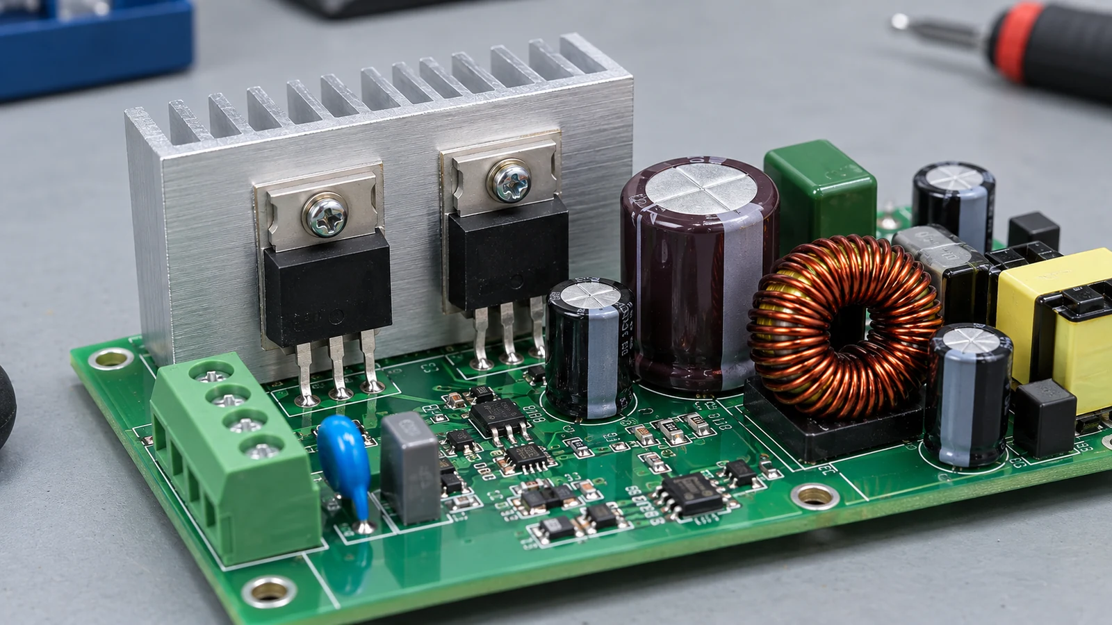
For a tall heat sink, define the clamp force and reaction structure so that assembly does not overload the semiconductor package. A thermal interface is not, by itself, evidence of structural retention. Check fastener access, load-spreading features, insulation requirements, and freedom for differential movement. Confirm those details against the selected package and heat-sink attachment specifications.
Protect the Board During Depanelization and Transport
Depanelization and transport need their own support arrangements because panel rails and enclosure mounts are not continuously available. Plan the transition from the supported panel to the individual board, then to the shipping tray, before approving component placement near an edge.
Keep the separation tool and its approach clear of overhanging bodies. Place supports so that the final cut does not leave the heavy end of the board hanging from the last tab. Do not use the connector or heat sink as a handle. The referenced supplier warns that placing an overhanging part over a break-routing tab can prevent separation or damage its solder connection. [3]
Packaging should locate the board at approved regions and protect protrusions from contact with the tray lid, neighboring boards, and carton walls. Restrain movement without forcing the component body against its leads. Provide unloading access that does not require pulling on the tallest part. Preserve the agreed electrostatic-protection requirements while evaluating mechanical restraint; cushioning and electrical protection are separate functions.
A vibration profile must describe more than an acceleration number. Record the frequency range, power spectral density profile, overall acceleration, exposure duration, axes, and mounting condition. Do not substitute overall random-vibration acceleration for a deterministic peak in the simple force calculation. Assess the response at the component support, not only at the transport container. IEC 60068-2-64 addresses broadband random vibration and the associated structural or functional degradation. [7]
Match the verification method to the assembly state
| Method | Appropriate question | Project information still required |
|---|---|---|
| IEC 60068-2-64:2008+AMD1:2019 | Does the specified specimen withstand broadband random vibration? | Spectrum, duration, axes, mounting, instrumentation, and acceptance criteria |
| IEC 60068-2-27:2008 | Does the specified specimen withstand the selected shock exposure? | Pulse shape, amplitude, duration, directions, repetitions, and mounting |
| ISTA 3A | Does an individual packaged product suit the relevant parcel-distribution test scope? | Package configuration, applicable category, shipment conditions, and damage criteria |
IEC shock and vibration methods do not assign one universal severity to all PCB assemblies. ISTA 3A addresses individual parcel shipments of 150 lb (70 kg) or less, with standard, small, flat, and elongated package categories. That limit concerns the packaged product, not a component’s permitted mass. Specify the applicable controlled procedure and acceptance criteria in the test plan. 7[9]
Release a Support and Clearance Checklist with the Build
For PCB overhanging heavy components assembly, release the support and clearance checklist as controlled manufacturing information. Each row needs a named accountable role, an approved physical arrangement, and evidence that the actual operation can be completed without overloading the assembly. The following matrix identifies decisions to resolve, rather than recording test results.
| Load or Access Case | Affected Feature | Support Needed | Clearance Check | Responsible Owner |
|---|---|---|---|---|
| Transformer or inductor mass | Body, stabilizing features, leads, pads, and nearby PCB span | Approved body restraint or verified package retention; local board support during handling | Carrier contact, solder access, core clearance, and removal path | OEM mechanical engineer; manufacturing engineer owns temporary tooling |
| Overhanging connector | Housing, hold-downs, edge pads, panel rail, and enclosure opening | Qualified hold-downs or housing bracket; defined support before enclosure installation | Below-board protrusion, rail/tab position, mating envelope, and bracket fasteners | OEM mechanical engineer with PCB layout engineer |
| Tall heat sink | Heat-sink mass, package surface, clamp, and mounting holes | Retention transferring inertia and clamp reactions into approved supports | Driver approach, lid clearance, airflow path, and lifting/removal envelope | OEM thermal/mechanical engineer |
| Cable insertion load | Mating housing, terminals, solder joints, and local PCB region | Local reaction fixture or enclosure restraint; cable strain relief where specified | Plug travel, latch release, cable bend, and supporting-hand access | System integration engineer; manufacturing engineer owns mating fixture |
| Panel separation | Remaining tabs, component-side moment, and cut-adjacent laminate | Depanelization nest supporting the loaded region through the final cut | Cutter path, overhang, support removal, and transfer into the tray | Manufacturing engineer |
| Shipping vibration exposure | Heavy bodies, unsupported board spans, brackets, and tray contacts | Board restraint and component protection validated with the packed assembly | Lid/sidewall gaps, adjacent-board contact, cushion movement, and unloading access | Packaging engineer; quality engineer owns test acceptance |
Record a measurable clearance decision
For a non-electrical mechanical gap, use minimum gap = nominal gap − tolerance allowance − relative movement. Define the allowances in the direction that closes the gap; use a documented tolerance model rather than adding unrelated dimensions.
An illustrative review uses 3.0 mm nominal housing-to-tray clearance, a 1.2 mm worst-case tolerance allowance, and 0.6 mm predicted relative movement. The remaining gap is 1.2 mm. Against a project-defined 1.0 mm minimum, this gives 0.2 mm margin. The requirement and movement estimate are example project inputs, not industry rules; replace them with the released geometry and verified transport response.
Make the handoff executable
Release the component load record, assembly and enclosure drawings, fixture revisions, installation order, retention specifications, packaging drawing, and inspection/test criteria together. State who installs the permanent retention and exactly when the temporary support can be removed.
Make acceptance observable. Specify allowable permanent displacement, prohibited contact, retention loosening, and relevant crack or damage criteria. Identify inspection locations and compare the assembly before and after the prescribed exposure. Define functional checks and any required continuity monitoring during loading; a post-test power-on check alone can miss intermittent faults. Record the tested hardware, fixture, and packaging revisions.
The mechanical owner accepts the load path; manufacturing accepts the operation and tooling; packaging accepts restraint and handling; quality accepts the verification record. Reject release when a required support is missing, the cut or mating path is obstructed, or no owner has accepted the applicable load case. Reopen the review after a component, cable, bracket, panel, or packaging change that alters that case.
Five Application Scenarios
Heavy-component support decisions change with the assembly state. Apply the same review to these five configurations, preserving the actual part specifications and load directions instead of copying one fixture arrangement across products.
Industrial power board with a transformer
A transformer may be retained in the finished enclosure but unsupported after soldering. Define a carrier or approved body restraint for inspection and transfers, then specify the enclosure attachment sequence. Verify that releasing the carrier does not bend the board or make the transformer leads the temporary lifting structure.
Edge-mounted industrial I/O connector
An overhanging connector may fit the enclosure yet conflict with the panel rail or separation tool. Resolve the panel geometry before fabrication and provide support during plug-in testing. Verify the housing bracket and PCB datums together so enclosure installation does not push a previously aligned connector sideways.
Power-control board with a tall heat sink
A tall heat sink creates inertial loads even when no operator touches it. Review its center of gravity, clamp reaction, and mounting support in all relevant orientations. Installing it after reflow may simplify the process, but only when the remaining fasteners and package surfaces remain accessible for controlled assembly.
Kiosk controller with a service harness
A service connector experiences mating, unmating, and cable-routing loads. Provide a reaction point that is available during servicing, not merely during factory assembly. Check latch-release access with neighboring modules installed. Separate normal connector operation from pulling on the cable to extract the board, and prohibit the latter handling method.
Spare assemblies shipped without an enclosure
A spare PCBA may lack the chassis supports used in the complete product. Qualify its own tray and protective arrangement, including removal at the destination. Evaluate the packed spare configuration rather than treating finished-equipment transport results as proof. Keep protected gripping areas visible and avoid packaging that requires using a component as a handle.
Frequently Asked Questions
Heavy and overhanging PCB component reviews should close these support decisions before the manufacturing release.
When does a heavy PCB component need mechanical support?
A component needs additional support when its specified loads exceed the qualified capability of the package, joints, or supporting board. Review mass, center of gravity, acceleration, cable forces, and every handling state. There is no universal gram limit that replaces the component specification and a verified load path.
Can solder joints alone retain an overhanging connector?
Solder joints alone are acceptable only when the selected connector and board attachment are qualified for the actual loads. Overhang, cable stiffness, mating force, and repeated handling can make that assumption unsuitable. Use the manufacturer’s retention features and add a verified bracket or reaction support where the load assessment requires it.
Should support fixtures be considered before the layout is frozen?
Yes, support fixtures should be reviewed before layout freeze because they need physical contact regions, locating features, and access. Reserve space for the fixture and its removal path while coordinating panel rails, soldering, and inspection. A late fixture cannot correct an inaccessible support location without changing the process or board.
How can cable insertion load affect assembly reliability?
Cable insertion can bend the board or apply a moment to the connector attachment when the force is reacted far from the housing. Misalignment and stiff cable routing can add loads beyond an idealized contact-force estimate. Provide local reaction support and verify the complete mating operation with the intended cable.
Which packaging checks matter for boards with tall or heavy parts?
Check board restraint, protrusion protection, lid and sidewall gaps, neighboring-board contact, and unloading access. Evaluate tolerances and relative motion, not just a static fit. Test the actual packed configuration against the selected distribution conditions, with defined inspection and functional acceptance criteria before and after exposure.
Is adhesive a substitute for a mechanical bracket?
Adhesive can replace or supplement a bracket only when the material, joint geometry, process, and environmental performance are qualified for that load path. Specify application and cure requirements, substrate compatibility, inspection, and rework access. A generic instruction to add glue does not establish retention strength or long-term suitability.
Can a heavy component be installed after reflow?
Yes, later installation can be appropriate when the component and approved soldering or fastening process permit it. Confirm access to its joints and hardware, support the board during installation, and define inspection afterward. The revised sequence must also protect nearby components and avoid an unsupported transfer before final retention.
How should mechanical retention be verified before production release?
Verify retention against a documented load case using the intended board, hardware, assembly sequence, and mounting condition. Combine appropriate analysis with assembly trials and specified mechanical or transport tests. Record clear acceptance criteria and traceable revisions; a successful visual inspection alone does not demonstrate performance under the intended loads.
Next Step: Prepare a Mechanical Assembly Review Package
A useful review package combines the BOM and PCB data with component mass properties, mating-force specifications, enclosure geometry, support drawings, and shipping conditions. Identify the operations that occur before permanent retention is installed, and request separate agreement on temporary tooling, retention installation, inspection, and packaging.
For a JASPER PCB assembly services enquiry, submit that package with quantities and the required assembly revision. Ask for the support and clearance decisions to be closed before production release, with system-level mechanical validation assigned to its responsible owner.
Ready to Start Your Project?
Tell us about your membrane switch, keypad, or graphic overlay requirements. Our engineering team will review your specifications and provide a detailed quote.