
Metal Domes for Membrane Switches
A metal dome is a formed spring contact that snaps from open to closed under load, giving a membrane switch tactile feedback and momentary electrical contact. This guide selects the published Snaptron F07280 as its mid-to-high comparison point: 7 mm four-leg geometry, 280 gf ±30 gf typical trip force, 0.38 mm reference travel, and up to 5,000,000 component cycles.
Last updated: 2026-07-28
Selected Engineering Reference
Use the F07280 record below when an OEM drawing leaves the dome open. Naming the source model keeps its component limits separate from the finished membrane-switch specification.
| F07280 parameter | Published value | Source and scope |
|---|---|---|
| Contact configuration | SPST, normally open | Snaptron F07280 component record |
| Dome geometry | 7 mm four-leg | Snaptron F07280 component record |
| Dome height | 0.46 mm | F07280 Dim. C |
| Reference travel | 0.38 mm | F07280 travel, marked Ref. |
| Trip force | 280 gf ±30 gf typical (2.75 N ±0.29 N) | F07280 Fmax/Force |
| Component life | Up to 5,000,000 actuations | F07280 loose-component rating |
| Switching voltage | 0.1–50 VDC | F07280 component limit |
| Switching current | 0.05–100 mA DC | F07280 component limit |
| Switching capacity | 1 W maximum | F07280 component limit |
| Contact bounce | <0.3 ms make; <0.6 ms break | F07280 component value |
| Base material | SSTL | F07280 component record |
| Plating options | Nickel, silver or gold | F07280 component options |
| Operating temperature | −45°C to +100°C | F07280 component rating |
| Dome-cavity dimension X | 6.35 mm | F07280 drawing dimension |
The values above come from the Snaptron F-Series product record. Every line remains scoped to that traceable reference component.
Integration values used with the reference
| Integration parameter | Guide value | Source and scope |
|---|---|---|
| Tactile target | 45% | Selected upper-middle value within INOVAN’s published 30–50% typical ΔF/F band |
| Stainless grade cross-check | 1.4310 | INOVAN general snap-dome specification |
| Selected comparison finish | Nickel | Guide selection; F07280 also lists silver and gold |
| Contact resistance reference | Nickel <1 Ω; gold <100 mΩ | INOVAN assembly-dependent standard values |
| Guide temperature window | −40°C to +85°C | INOVAN general operating range, inside the F07280 rating |
| Production actuator | Flat-bottom, centered, ≤1.75 mm diameter | Snaptron maximum of 25% of a 7 mm dome diameter |
| Loose-dome test probe | 1.27 mm flat probe | Snaptron force-test procedure for domes ≥5 mm |
| Venting | Defined route from every closed pocket | Snaptron integration guidance |
INOVAN publishes the material, tactile and resistance references in its snap-dome technical brochure. The released project drawing sets the final dome, pad, actuator, tolerance, finish and completed-switch life target.
Published 7 mm Force Comparisons
The F-Series catalog provides lower and higher forces at the same 7 mm diameter. Comparing one diameter first reduces the number of geometry variables during sample evaluation.
| Published part | Diameter | Typical trip force | Dome height / travel | Component life | Comparison role |
|---|---|---|---|---|---|
| F07150 | 7 mm | 150 gf ±30 gf | 0.38 mm height | Up to 5,000,000 | Lighter-force sample |
| F07200 | 7 mm | 200 gf ±30 gf | 0.43 mm height | Up to 5,000,000 | Medium-force sample |
| F07280 | 7 mm | 280 gf ±30 gf | 0.46 mm height / 0.38 mm reference travel | Up to 5,000,000 | Selected guide reference |
| F07320 | 7 mm | 320 gf ±30 gf | 0.46 mm height | Up to 5,000,000 | Heavier-force sample |
These values are published on the Snaptron F-Series page. Select the lowest force that prevents unintended operation while meeting the installed tactile target. Make the final comparison through the real overlay, spacer, circuit and enclosure support.
For automated solder placement, Snaptron’s S-Series white paper lists solderable four-leg domes from 6.3 to 14 mm, 280 to 550 gf, nickel plating and a 1,000,000-cycle component rating.
How a Metal Dome Produces Tactile Feedback
A metal dome begins in a stable convex shape. A centered actuator increases load until the dome reaches its peak force. The dome then snaps through, its center contacts the circuit pad, and the spring geometry recovers when the load is removed.
Use one force vocabulary throughout a test report. INOVAN defines maximum actuation force as F, return/contact force as FR, and the force drop as ΔF = F − FR. Its snap formula is:
Snap ratio = (F − FR) ÷ F × 100%
INOVAN publishes a typical ΔF target of 0.3–0.5 × F. This guide selects 45% as the upper-middle comparison value. Snaptron’s procedure uses Fmax, Fmin, Fc and Fb for a different force-curve notation, so the report keeps INOVAN’s FR and Snaptron’s Fmin as separate definitions.
Travel is the displacement from the relaxed dome to electrical contact. Snaptron lists 0.38 mm as the reference travel for F07280. Its dome-handling guidance states that most domes are depressed to the flat plane and no farther; set production stroke from the selected dome drawing.
Snaptron’s loose-dome procedure defines Fmax, Fmin, Fc, Fb and their corresponding travel points. ASTM F2592-16 covered membrane-switch force-displacement measurement but was withdrawn in 2023 without replacement. ASTM F1578-24 remains active for contact-closure cycling.
Metal Dome Shapes and Supply Formats
Four-leg, round, triangle, oblong, and SMT domes solve different packaging and force problems. The shape changes how the dome is supported, how closely keys can be spaced, and how force is transferred to the circuit.
| Type | Best fit | Typical strength | Design attention |
|---|---|---|---|
| Four-leg | General membrane switches, FPCs and PCBs | Broad force range, stable support, strong life options | Align all four feet and center the actuator |
| Round | Compact circular pads and simple layouts | Symmetric footprint | Force and tactile ratio depend strongly on diameter |
| Triangle / three-leg | Dense key layouts and small devices | High tactile ratio in a small envelope | Orient legs to the matching pad and pocket |
| Oblong | Long or narrow key zones | Fits rectangular mechanical envelopes | Control orientation and off-axis loading |
| SMT solder dome | Automated PCB or FPC assembly | Accurate placement without a separate adhesive carrier | Use the specified solder process and board support |
| Dimpled dome | Concentrated center contact | Smaller electrical contact area | Match dimple position to the pad design |
| Center-hole dome | LED or optical path through the dome | Combines tactile and visual feedback | Coordinate LED clearance, actuator ring and venting |
Use a four-leg dome for the selected 7 mm / 280 gf comparison. An adhesive PET array fixes pitch and orientation for multi-key layouts. Loose domes support prototype comparison or a separate mechanical retainer. Choose SMT domes when the assembly process requires automated placement and reflow.
Snaptron’s DT-Series data documents center-hole backlighting, two electrical contact levels, loose packaging and adhesive arrays.
Actuator, Support, Spacer and Vent Rules
Actuator geometry and support change the measured installed response. Apply these four rules to the 7 mm reference design:
- Use a flat-bottom, centered production actuator no larger than 1.75 mm in diameter.
- Use a 1.27 mm flat probe and ±0.254 mm centering for loose-dome force testing.
- Test the loose dome on a hard, flat, vented fixture.
- Set production stroke from the selected dome drawing and vent every closed pocket.
Snaptron’s force-test procedure specifies the 1.27 mm probe and ±0.254 mm test centering. Its separate actuator guidance limits a flat, centered production actuator to 25% of dome diameter; for 7 mm, the maximum is 1.75 mm.
The spacer pocket locates the dome and gives it clearance to move. Snaptron lists a 6.35 mm X cavity dimension for F07280; use the selected part drawing for the final cavity and contact pad, and keep adhesive outside the moving surface.
Provide a vent path unless the carrier or circuit already vents the pocket. A spacer channel can connect adjacent pockets, a PET array can vent through the carrier, or a PCB/FPC can use a vent via. Snaptron’s venting guidance states that trapped air causes a significant loss of tactile response.
PET, FPC and PCB Integration
Metal domes work with printed PET circuits, copper FPCs, and rigid PCBs when the pad, support, retention, and vent path are designed as one interface.
| Circuit | Recommended construction | Contact and support rule | Production fit |
|---|---|---|---|
| Printed PET | Dome array or retainer over a printed contact pattern | Keep the contact flat, clean and fully backed | Thin laminated membrane switches |
| Copper FPC | Adhesive array over a plated copper pad with local stiffener | Support the dome area so flexing does not absorb the snap | Compact assemblies with routed tails |
| Rigid PCB | Adhesive array, pocket retainer, or solderable SMT dome | Use the supplier-matched pad and keep nearby components outside the dome envelope | High-volume electronic assemblies |
For rigid or flex copper pads, choose the finish by cycle target. Snaptron’s plating guide recommends 5.0–12.5 µm of bright hard nickel or 0.76–1.27 µm of hard gold when the target exceeds one million cycles. ENIG is listed for lower-cycle applications. These thicknesses apply to the circuit contact surface; specify the dome finish separately.
Use nickel as the selected comparison finish. INOVAN publishes assembly-dependent standard values of <1 Ω for nickel and <100 mΩ for gold. Select the dome and pad finishes together from the contact-resistance and cycle requirements.
The contact pad should come from the selected dome series rather than a generic copied footprint. Provide the circuit artwork, dome center coordinates, keep-out zones, tail or connector route, and local support thickness in the released drawing.
Electrical, Environmental and Life Limits
The F07280 record specifies 0.1–50 VDC, 0.05–100 mA DC and 1 W maximum, positioning it as a signal contact. Set firmware or hardware debounce from the published <0.3 ms make and <0.6 ms break values, then verify the installed stack.
Use −40°C to +85°C as this guide’s design window. It matches INOVAN’s published general operating range and stays inside the −45°C to +100°C F07280 rating. Qualify the complete switch across the project temperature range because the overlay, adhesive, circuit, enclosure and dome form one stack.
F07280 is published at up to 5,000,000 component actuations. Define the completed-switch cycle count in the project specification and test the assembled key to that number. ASTM F1578-24 supplies the cycling method; the project specification supplies the pass count.
Verification Plan for Samples and Production
The release specification needs an exact component record and a repeatable test setup. Use this sequence:
- Measure the loose dome. Use a calibrated force-displacement gauge, a 1.27 mm flat probe, a hard vented fixture, and 1.27 mm/s test speed.
- Precondition consistently. Cycle the dome ten times and record the force-displacement curve on the eleventh actuation, following Snaptron’s published test procedure.
- Measure the assembled key. Repeat the curve through the actual overlay, actuator, spacer, circuit, and enclosure support.
- Run contact-closure cycling. Use ASTM F1578-24 or the project-defined equivalent; set the cycle count and optional electrical monitoring in the project specification.
- Release the drawing. Record dome model, geometry, nominal force and tolerance, travel, tactile target, pad finish, actuator, pocket, vent, test method, life target, and change-control triggers.
For the loose F07280 reference, record 280 gf ±30 gf typical trip force and 0.38 mm reference travel. For the completed key, define force, travel, tactile ratio, contact resistance and life limits after measuring the approved overlay, spacer, circuit and enclosure stack.
Incoming and in-process inspection should verify dome orientation, carrier registration, pocket alignment, contamination, adhesive intrusion, vent continuity, pad finish, and visible dome damage. Electrical inspection should confirm closure, open-circuit recovery, resistance, and bounce against the released control plan.
Common Failure Modes and Corrections
| Symptom | Most likely cause | Direct correction |
|---|---|---|
| Weak click | Oversized actuator, trapped air, soft backing, excessive overlay damping | Reduce actuator diameter, add venting, stiffen support, retest installed curve |
| Heavy force | Trapped air, preload, thick overlay stack, off-center load | Open the vent path, remove preload, center the actuator |
| Stuck or inverted dome | Over-travel or unsupported feet | Add a hard stop and fully support the perimeter or legs |
| Intermittent contact | Contamination, dome shift, poor pad finish, uneven support | Clean the interface, correct retention, upgrade the contact finish |
| Force variation across keys | Carrier registration, pocket variation, actuator offset | Tighten array registration and centerline tolerances |
| Early pad wear | Finish too soft for the cycle target or sliding contact | Use hard nickel/hard gold and eliminate lateral actuator motion |
| Array lift | Inadequate lamination pressure, contaminated surface, narrow bond land | Correct surface preparation, adhesive land and lamination process |
| Audible click but no signal | Incorrect pad geometry or contact resistance | Match the pad to the dome series and verify electrical closure under load |
Before changing dome force, inspect the actuator, support, vent, pad and retainer.
JASPER Metal Dome Samples
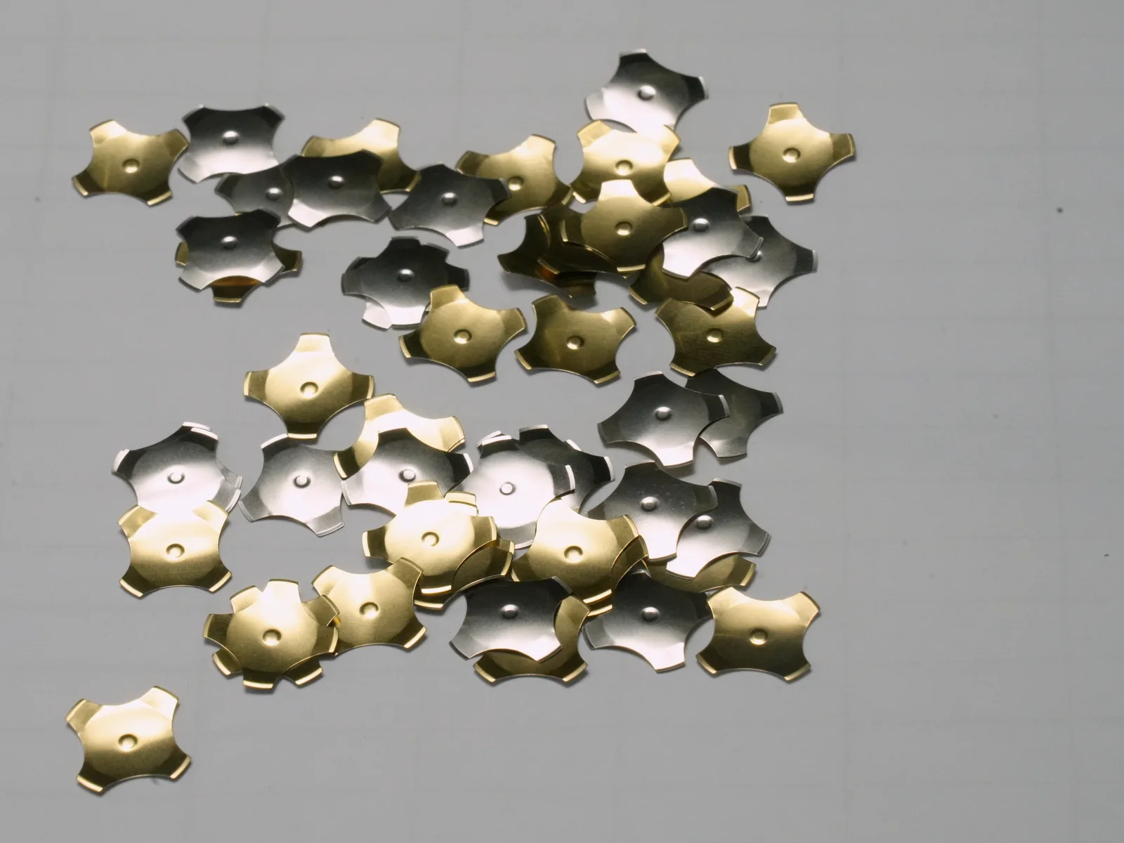
The following JASPER photographs show four-leg and oblong metal-dome forms used during material and geometry review.
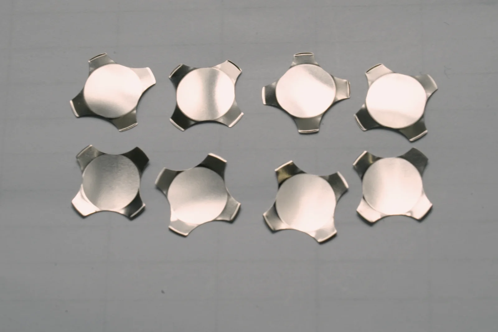
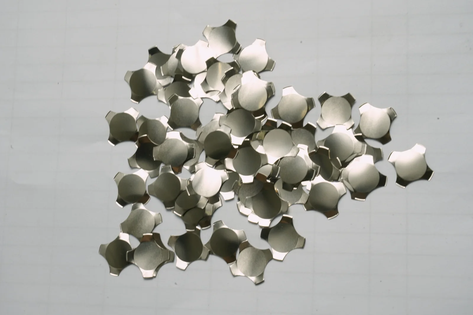
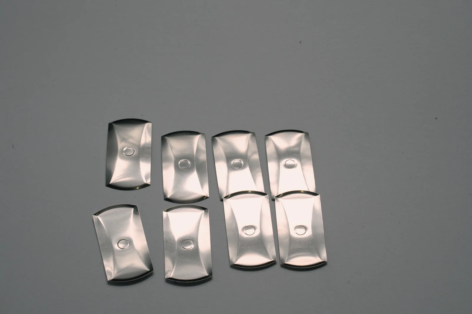
The numerical baseline on this page comes from the cited technical records; the photographs document the physical forms shown.
Related Products and Engineering Guides
- Custom metal dome membrane switches for quotation, stack design and production.
- Tactile membrane switches for metal dome, polyester dome and embossed-overlay options.
- PCB and FPC membrane switches for copper circuit and board-backed assemblies.
- Metal dome force selection guide for operator scenarios and force bands.
- Membrane switch design guide for drawings, tolerances and layer-stack inputs.
- Materials Center for overlays, adhesives, circuits, backlighting, silicone, rigid panels and sealing materials.
Send the key layout, circuit artwork, available height, use conditions, force preference, life target and enclosure section to request a dome-stack review. Use the 7 mm / 280 gf reference as the first comparison point.
Frequently Asked Questions
What is the recommended starting metal dome specification?
Use Snaptron F07280 as the comparison point: 7 mm four-leg geometry, 280 gf ±30 gf typical trip force, 0.38 mm reference travel and up to 5,000,000 component cycles. Use a flat, centered production actuator no larger than 1.75 mm and define completed-switch life in the project specification.
Is 280 gf too heavy for a membrane switch?
A 280 gf dome is a firm comparison point. Compare the published 150 gf, 200 gf, 280 gf and 320 gf F-Series samples in the installed stack to validate operator ergonomics before releasing the force value.
What is the correct actuator size for a 7 mm dome?
Use a flat-bottom, centered production actuator no larger than 1.75 mm. The 1.27 mm dimension belongs to Snaptron’s loose-dome force-test probe, and ±0.254 mm is the force-test centering limit.
What tactile ratio gives a crisp click?
Use 45% as the guide target. INOVAN defines snap ratio as (F − FR) / F × 100% and publishes 30–50% as the typical ΔF/F band.
Do metal dome pockets need venting?
Yes, vent them by default. Connect pockets through the spacer, vent through the PET carrier, or add a PCB/FPC via. Trapped air raises apparent force and weakens tactile response, so the vent route belongs on the released layer drawing.
Can the same metal dome be used on PET, FPC and PCB circuits?
The same dome geometry can work on all three when each circuit uses the correct pad, local support, finish, retainer, and vent. Printed PET needs a fully backed flat contact; FPC needs a stiffened dome zone; PCB designs can use arrays, retainers, or SMT domes.
How many cycles should a metal dome switch pass?
F07280 is published at up to 5,000,000 component actuations. Set the completed-switch cycle target in the project specification and test it under ASTM F1578-24 or an equivalent defined method.
When is gold preferable to nickel contacts?
Nickel is the selected comparison finish. INOVAN publishes assembly-dependent values of <1 Ω for nickel and <100 mΩ for gold; Snaptron publishes separate hard-nickel and hard-gold pad thicknesses for targets above one million cycles.
Why does a dome become weak or stay inverted?
The usual causes are over-travel, an actuator that is too large or off-center, unsupported feet, trapped air, preload, or a deformed transition ring. Restore flat support, center the actuator, limit travel at the foot plane, and verify the vent before changing force.
Data Source and Project Release
The published F07280 and INOVAN values above are industry reference data. The released project drawing controls the JASPER production configuration and completed-switch acceptance limits.
Review the 7 mm / 280 gf Reference
Send the key layout, circuit artwork, available height, operator conditions, and life target. Lock the dome model, actuator, venting, pad finish, and completed-switch test plan before release.