
Backlighting and Optical Materials
Backlit interfaces depend on an optical system, not a single bright component. The source creates light; a guide or optical cavity distributes it; diffusers soften local intensity; reflectors redirect lost light; blockers control leakage; and translucent inks, icons, and windows determine what the operator finally sees. A useful material review therefore starts with the artwork, viewing conditions, available power, circuit layout, and mechanical stack.
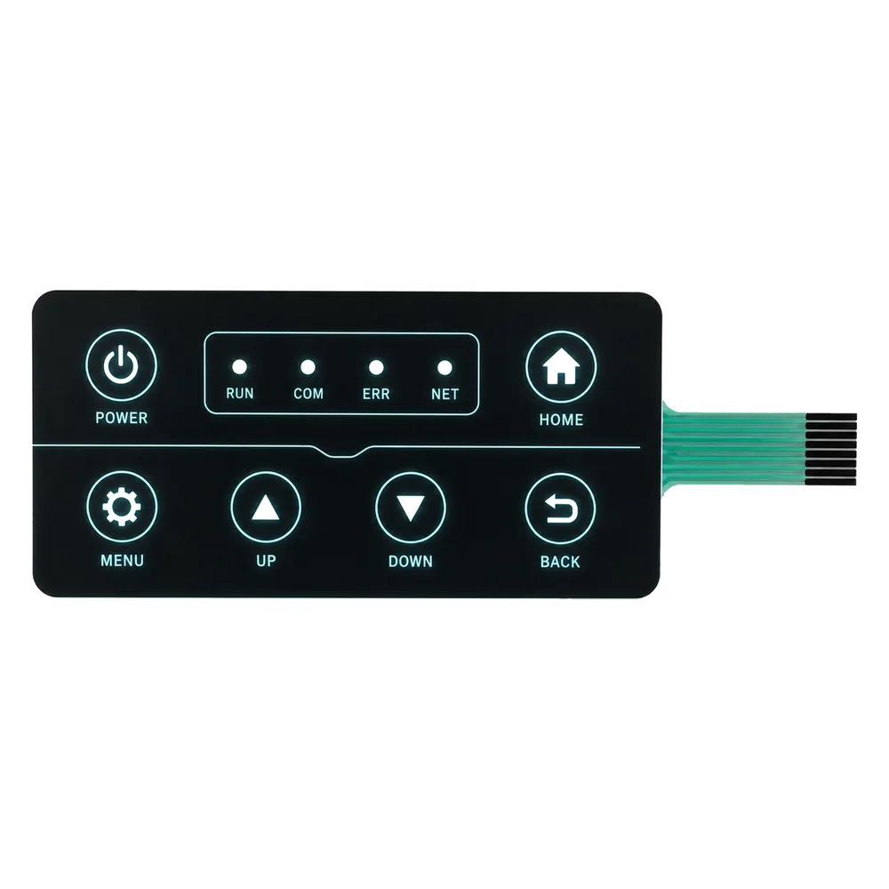
Quick Selection Facts
Select membrane switch backlighting materials around the finished interface, not from an isolated material list.
| Review input | Why it matters | What to provide |
|---|---|---|
| Illuminated area | Small icons and broad legends distribute light differently | Artwork showing lit and unlit features |
| Uniformity | A status indicator and a presentation surface may have different visual targets | Approved sample or priority ranking |
| Color | Source, ink, film, and viewing angle interact | Target color and lit/unlit intent |
| Brightness | Ambient light and viewing distance change the useful target | Actual viewing conditions |
| Power and circuit | Drive conditions, source count, space, and heat shape the layout | Supply and circuit information |
| Stack space | Optical layers must fit the circuit, adhesive, and enclosure | Cross-section and available space |
| Environment | Cleaning and exposure can affect the construction | Exposure description and validation need |
No input decides the construction alone. More diffusion may hide source points but reduce transmitted light; denser blocking may control edges while making registration more critical.
Optical Material Stack
An optical stack may use some or all of the following elements. Availability and suitability should be confirmed against the current project, approved materials, and validation plan.
| Layer or element | Engineering role | When it may be considered | Main limitation to review |
|---|---|---|---|
| LEDs | Create light at indicators or at a guide edge | Local indicators or controlled zones | Hot spots, placement, circuit space, power, and heat |
| Light guide film (LGF) or guide layer | Moves light from a source across a wider area | Thin distributed illumination | Pattern, coupling, bends, cutouts, and stack pressure |
| Diffuser film or printed diffusion | Blends intensity and softens source points | Icons needing a smoother appearance | Lower apparent brightness or softer boundaries |
| Light-blocking ink or mask | Limits glow around legends, windows, and edges | Dead-front areas and adjacent icons | Pinholes, registration, density, and leakage |
| Reflective layer | Redirects light toward the viewing surface | Cavities where light may escape into the enclosure | Gaps, wrinkles, contamination, and orientation |
| Translucent overlay ink | Creates illuminated color and defines the icon | Colored legends and warning symbols | Appearance varies with source, ink, film, and ambient light |
| Clear or tinted window | Provides a viewing path to a display or indicator | Display and status windows | Haze, distortion, scratches, adhesive, and reflection |
| EL or fiber-optic concept | A possible alternative for specific constraints | Only after supply, drive, stack, and validation review | Availability and performance must not be assumed |
An LGF does not create uniformity by itself. Source coupling, extraction pattern, reflection, diffusion, icon geometry, and layer spacing still govern the result.
Light Distribution Decisions
Start with source position. An edge source must couple into the guide without creating a bright entrance zone. A source beneath an icon shortens the path but may expose the LED point. Shared guides must account for distance, cutouts, tail routing, and interruptions from adhesive or spacers.
The guide pattern controls where light exits. Changing the artwork, source location, or panel dimensions may require a new pattern. Broad features, narrow legends, and closely spaced symbols do not necessarily share the same release and blocking strategy.
Diffusers blend local intensity; reflectors redirect light toward the operator; blockers define the dark field. None can compensate for every source or guide problem. Gaps, surface defects, poor density, or misregistration may remain visible as dim zones or leakage.
Mark each icon as always lit, conditionally lit, unlit, or hidden when off. This separates ordinary graphics from dead-front requirements before materials are selected.
Overlay and Window Interaction
The overlay is the final optical filter. Base film, printed color, texture, and viewing angle change the perceived result. A translucent ink may match a proof yet look different over the actual source, so approval should cover both lit and unlit states.
Dead-front graphics balance inactive concealment with illuminated legibility. Ink density, source output, blocker geometry, ambient light, and background color must be reviewed together on a representative construction.
Display windows prioritize visibility through the stack, making haze, texture, adhesive boundaries, printed edges, and particles conspicuous. A tint may help inactive appearance or contrast, but it needs review with the actual display.
Gloss may preserve clarity but show reflections; texture may reduce glare while softening detail. Viewing angle, window finish, and stack spacing therefore belong in the optical review.
Manufacturing Implications
The production drawing should define source coordinates, icon registration, blocker boundaries, windows, adhesive-free optical zones, and the orientation of guide, diffuser, and reflector layers.
Printed density and LED placement need clear controls because variation becomes visible under illumination. Multiple printed layers may support color or blocking, but the construction must be confirmed for the project.
Fibers, dust, fingerprints, liner debris, and adhesive contamination may become obvious after illumination. Lamination sequence can also affect wrinkles, particles, and alignment, so optical faces need controlled handling.
Inspection should compare defined lit and unlit conditions for icon visibility, hot spots, dim regions, color, leakage, contamination, and alignment. Acceptance limits must come from project requirements or approved samples.
JASPER’s graphic overlay printing capability is a useful related review point when optical behavior depends on printed blockers, translucent legends, dead-front graphics, or windows.
Common Failure Modes
| Visible symptom | Likely areas to investigate | Corrective direction |
|---|---|---|
| Bright spot near a source | Source-to-guide coupling, insufficient diffusion, short optical path | Revisit source position, guide pattern, diffuser, or icon placement |
| Dim icon or dim zone | Guide extraction, excessive blocking, poor reflection, distance from source | Check each optical layer before simply increasing source output |
| Glow around an icon | Blocker density, blocker registration, layer gap, reflective path | Refine the mask and inspect alignment through the full stack |
| Visible LED point | Direct source view, inadequate diffusion, insufficient optical distance | Add or adjust diffusion, redirect the source, or change the cavity |
| Color shift | Source color, translucent ink, film tint, viewing angle | Approve color with the actual lit construction |
| Partially blocked icon | Print registration, adhesive intrusion, misaligned guide or mask | Strengthen datums and inspect the laminated stack |
| Window haze or particles | Film finish, contamination, adhesive edge, trapped debris | Protect optical faces and revise cleaning or lamination controls |
For symptom-led diagnosis, see how to reduce light leakage through optical stack design.
Alternatives and Design Boundaries
Optical materials should be chosen after the lighting architecture is understood. Direct LEDs, edge-coupled light guides, and other lighting approaches solve different problems. The guide compare LED, LGF and other backlighting approaches keeps that system-level comparison separate from this material reference.
This page does not establish that every listed technology is currently supplied by JASPER. EL, fiber-optic, or specialty constructions remain concepts until availability, drive electronics, compatibility, and validation are confirmed.
It also defines no universal brightness, uniformity, power, color, lifetime, thickness, or temperature performance. Those outcomes depend on the complete design and acceptance method.
Use this page to define the stack, then review a custom backlit membrane switch or LED membrane switch and indicator integration when assembly and quotation are next.
Related Products and Applications
Backlighting is commonly reviewed where operators need to find controls in low ambient light, distinguish equipment states, or read compact indicators. Instrumentation is one relevant context because icon clarity, window readability, and controlled leakage can matter as much as nominal source output. See backlit interface materials for instrumentation for the application context.
Related paths:
- Materials for custom interface products
- Custom backlit membrane switches
- LED membrane switches and indicators
- Membrane switch backlighting options
- Graphic overlay printing
Engineering FAQ
What are the main optical layers in a backlit membrane interface?
A review separates the source, guide or cavity, diffuser, reflector, blocker, translucent icon, and window. Not every design needs every layer; their order follows the artwork, circuit, space, ambient light, and required appearance.
Does a light guide film guarantee uniform backlighting?
No. Coupling, extraction pattern, reflection, diffusion, cutouts, adhesive boundaries, icon size, and stack pressure all affect the result. Evaluate uniformity on the actual construction or a representative prototype.
How should dead-front icons be specified?
Identify the features hidden when off, their lit color, viewing distance, ambient conditions, and acceptable inactive visibility. Provide vector artwork and a reference sample when available. Review ink, blocker, source, and overlay together.
Can a brighter LED fix a dim or uneven panel?
It may help, but can intensify hot spots, leakage, power demand, or color differences. Inspect placement, guide behavior, diffusion, reflection, masks, and icon geometry before changing the source.
What files are useful for an optical material review?
Send icon and window artwork, circuit and source locations, enclosure section, available power, viewing conditions, lit and unlit requirements, color intent, stack-space limit, and any approved reference.
Share the Optical Requirements Before Freezing the Stack
For a useful RFQ review, provide the icon artwork, viewing environment, required colors, brightness target, available power, circuit information, source restrictions, enclosure section, and available stack space. Note which symbols are indicators, which must be evenly lit, and which must remain hidden when inactive.
Share icons, brightness and power requirements
Review the Complete Stack Before Tooling
Share the drawing, enclosure, operating conditions, assembly process, approval evidence, quantity, and timing. Unknown values can remain open items; they should not become assumed guarantees.