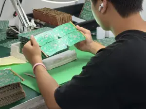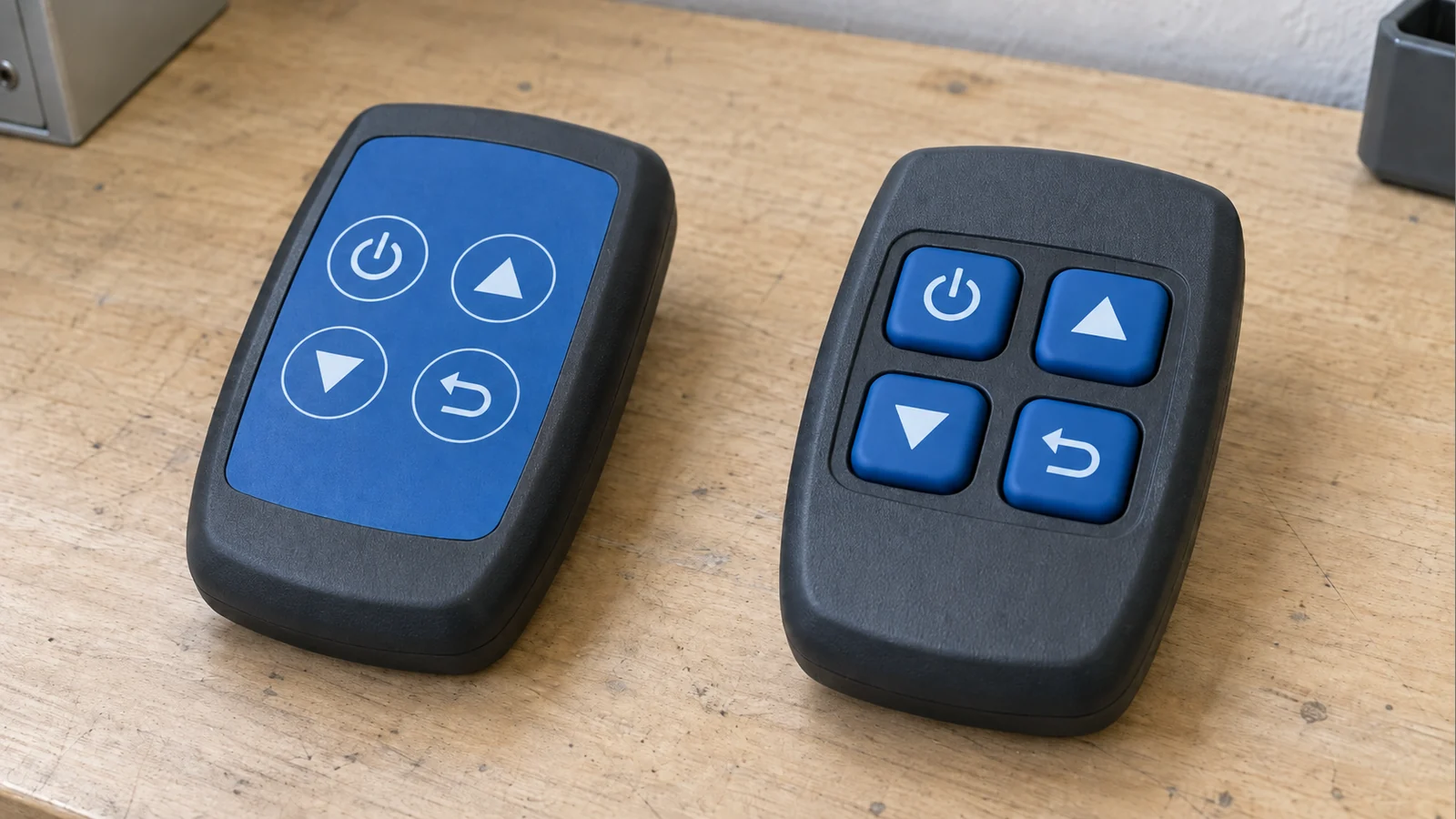
Replacing a flat membrane interface with raised silicone keys is usually a system redesign, not a cosmetic keycap change. The retrofit may preserve the controller electronics, pinout, tail connector, or even the existing membrane switching layer, but the front housing, key travel, actuator geometry, contact interface, sealing path, graphics, lighting, and installed force response must be checked again.
The first question is not “Can we copy the old key layout in silicone?” It is “Which functions of the old interface still work after the user surface becomes a moving three-dimensional part?”
- What Can Potentially Stay—and What Usually Changes?
- 1. Document the Existing Interface Before Changing It
- 2. Add Travel Without Creating a Housing Problem
- 3. Choose the Switching Architecture Before Tooling
- Route A: Keep the membrane circuit and add a silicone actuator
- Route B: Redesign the contact onto PCB/FPC pads
- Route C: Silicone over a metal dome or discrete switch
- 4. Rebuild Graphics, Backlighting, Sealing, and Cleaning Around the New Surface
- Graphics
- Backlighting
- Sealing and cleaning
- 5. Illustrative Before-and-After Retrofit Scenario
- 6. Prototype in Stages and Run Regression Tests
- 7. What to Send for an Engineering Review
- Discuss a Hybrid Keypad Assembly
What Can Potentially Stay—and What Usually Changes?
| Existing item | Retain candidate? | What must be checked before keeping it |
|---|---|---|
| Main controller PCB and firmware | Often | Input logic, pinout, electrical thresholds, and whether the new switch architecture presents the same signals |
| Membrane circuit and tail | Sometimes | Switch locations, local support, actuator compatibility, spacer/dome condition, travel, connector routing, and stack height |
| Metal dome layer | Sometimes | Dome position, actuator tip, preload, venting, stroke, support, and edge-press behavior |
| LED locations | Sometimes | New key height, optical path, legend location, light leakage, and diffuser/light-blocking needs |
| Connector and pinout | Often | Tail exit, bend path, mating height, strain relief, and circuit topology |
| Flat graphic overlay as user surface | Usually no | Raised keys normally move the tactile surface and often the legends into silicone or a new hybrid front |
| Front bezel/openings | Usually redesign | Key clearance, guidance, travel, hard stops, retention, seal compression, and assembly access |
| Sealing and cleaning concept | Revalidate | Raised geometry changes compression, wipe-clean behavior, and potential ingress/debris paths |
A retained part is only truly retained after it passes the new stack-up and validation plan.
1. Document the Existing Interface Before Changing It
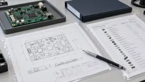
Create a section view from the operator’s finger to the product electronics. For the old interface, document the overlay, switch construction, circuit/tail/connector, LEDs, local support, housing features, sealing path, cleaning method, critical user requirements, and known field complaints.
Then build a retain/change/revalidate BOM. The purpose is to capture function and ownership, not just dimensions. JASPER’s current silicone keypad design guidance similarly treats the keypad, circuit, support, housing, lighting, and seal as one installed force path rather than separate parts.
2. Add Travel Without Creating a Housing Problem
A flat membrane switch can operate with little visible movement. A raised silicone key adds a molded web, actuator or conductive contact, clearance at rest, working travel, and return motion.
For each representative key, define:
- resting key height;
- moving key/web envelope;
- actuator or conductive contact;
- rest gap to the switching element;
- electrical actuation point;
- permitted overtravel; and
- hard-stop/bottoming and circuit support.
The bezel opening becomes functional. It must allow motion through the tolerance stack without rubbing, yet control excessive rocking. Large keys also need edge-press checks because users will not always press the center.
Do not use one uncontrolled housing compression to both seal the keypad and tune the key feel. Separate the seal path from the actuation path, then review minimum, nominal, and maximum stack conditions with the final fastening method.
3. Choose the Switching Architecture Before Tooling
Raised silicone keys can work with several electrical structures. The retrofit depth depends on what the old circuit can support.
Route A: Keep the membrane circuit and add a silicone actuator
This is the conservative route when the existing membrane circuit, tail, connector, and switch centers are still useful. The new silicone keymat becomes the molded user surface and presses the existing membrane switch or metal dome.
The electrical matrix may remain unchanged, but the actuator height, dome preload, spacer, vent path, bezel opening, and local support still require review. Rubber keypads can be combined with membrane or PCB-based switches and contact systems such as carbon pills or snap domes. Select the hybrid construction that meets the assembled interface’s mechanical and electrical requirements.
Route B: Redesign the contact onto PCB/FPC pads
If the old membrane layer is not retained, a silicone key can carry a conductive pill that closes a PCB, FPC, or other circuit pattern.
This changes the contact interface. Define pill/contact outline, pad geometry, worst-case overlap, rest gap, closure point, overtravel, board finish/cleanliness, and support below the pad. The old controller logic and connector mapping may survive, but the circuit artwork and mechanical stack become new design items.
Route C: Silicone over a metal dome or discrete switch
A silicone key can also actuate a separate dome or board-mounted switch. In that case, coordinate rubber travel, actuator shape, switch stroke, preload, support, and overtravel. For metal domes, trapped air can reduce tactile response; the referenced supplier recommends venting in most applications.
4. Rebuild Graphics, Backlighting, Sealing, and Cleaning Around the New Surface
Graphics
A flat membrane panel often carries all legends on one overlay. After conversion, legends may move onto key tops, remain on a bezel/secondary overlay, or be split between both. Decide which marks are permanent key legends, status icons, backlit symbols, warnings, or product-variant graphics, then validate the chosen printing/coating method for actual wear and cleaners.
Backlighting
Do not assume existing LEDs will work unchanged. Raised silicone alters LED-to-legend distance, wall thickness, viewing angle, light paths, and neighboring-key leakage. Review powered samples with the intended circuit, housing, coating/legend system, and ambient-light conditions.
Sealing and cleaning
A flat bonded overlay can provide a continuous wipe-clean front. Raised keys create a different exterior geometry and usually a different retention/compression concept. A molded perimeter lip can be one part of a seal, but it does not by itself prove enclosure ingress performance.
Also check whether liquid or debris can collect around key walls and whether repeated cleaning can affect legends, coatings, adhesives, or exposed housing interfaces.
5. Illustrative Before-and-After Retrofit Scenario
Illustrative example only—not a JASPER customer case or measured result.
Assume an industrial handheld controller uses a flat printed overlay over a tactile membrane switch. The redesign goal is easier key location while wearing gloves.
| Design area | Before | Raised silicone hybrid candidate |
|---|---|---|
| User surface | Continuous printed overlay | Molded silicone key tops with revised bezel |
| Switching | Existing tactile membrane/dome layer | Existing switch layer retained initially; silicone posts become actuators |
| Circuit/tail | Existing printed circuit and connector | Retained if centers, support, routing, and electrical behavior remain acceptable |
| Housing | Flat front aperture | New key clearances, locators, retention/compression, and travel envelope |
| Graphics | Overlay legends | Key legends move to silicone; fixed labels stay on bezel/secondary overlay |
| Backlight | Existing LED/window scheme | LEDs and light blocking re-evaluated for taller keys |
| Sealing | Bonded flat front surface | New perimeter/assembly seal validated in final housing |
| Verification | Legacy membrane checks | Installed force/travel, edge press, electrical closure, lighting, cleaning, sealing, and regression |
If the old membrane layer cannot tolerate the new actuator stack, the project should move to a redesigned PCB/FPC or other contact structure rather than forcing mechanical compatibility.
6. Prototype in Stages and Run Regression Tests
An early mockup can answer key reach, spacing, bezel clearance, glove access, enclosure interference, and basic alignment. It should not approve molded web behavior, final force, coating, or sealing.
With production-intent molded parts, test the installed assembly, including:
| Test area | What to verify |
|---|---|
| Mechanical | Clearance, rest height, return, interference, hard stop, fastener effects |
| Tactile | Force-displacement, travel, center/edge press, key-to-key variation |
| Electrical | First closure, stable closure, release, open state, required resistance/switch state |
| Contact alignment | Worst-case overlap and circuit support |
| Backlighting | Uniformity, hot spots, leakage, powered appearance |
| Graphics/coating | Alignment, adhesion, wear and cleaner exposure |
| Sealing/cleaning | Final enclosure compression, defined ingress/leak test, wipe access, debris traps |
| System regression | Input mapping, debounce assumptions, and other product tests affected by the redesign |
| Lifecycle | Representative high-use keys plus post-cycle mechanical/electrical/visual checks |
Freeze the fixture, sample state, and pass/fail criteria with the approved design.
7. What to Send for an Engineering Review
Send the current front-panel drawing/photo, old membrane drawing or sample, circuit/pinout/connector information, enclosure CAD or section, desired key behavior and glove requirement, backlight/legend requirements, cleaning and environment conditions, quantity, known field issues, and a list of parts you hope to retain. Unknown items can be marked TBD.
If the supplied boundary is unclear, review a complete silicone keypad assembly rather than the rubber keymat alone. If a tactile dome layer is likely to remain, review the metal dome membrane switch architecture. If the circuit must be rebuilt on a rigid or flexible substrate, compare the PCB and FPC membrane switch route.
Frequently Asked Questions
Can I replace only the flat overlay with a silicone keymat?
Usually not safely. The silicone key needs room to move, a controlled actuator/contact interface, location features, support, and a compatible sealing/retention method.
Can the existing membrane circuit and connector be reused?
Sometimes. Reuse is practical only when switch locations, support, tail routing, connector, and electrical behavior remain compatible with the new actuator geometry.
Do raised silicone keys require a new PCB?
No. A silicone keymat can actuate an existing membrane switch, metal dome layer, PCB/FPC contact pattern, or discrete switch.
Can the existing LEDs stay in the same locations?
Possibly, but optical performance must be checked again because the raised key changes the distance and light path to the legend.
Is a silicone keypad automatically easier to seal?
No. Silicone can provide molded sealing features, but ingress performance depends on the complete enclosure, compression path, joints, fasteners, exits, and validation method.
What is the lowest-risk way to start?
Start with the current assembly, representative cross-sections, circuit/pinout, and a retain/change/revalidate list. Prototype the mechanical stack before production tooling, then validate production-intent installed parts.
Discuss a Hybrid Keypad Assembly
For a retrofit review, send the current drawing or sample, enclosure section, circuit/pinout, connector details, quantities, device use, cleaning/environment requirements, backlight needs, and parts you want to retain. Mark unknown items as TBD.
Use the request a keypad engineering review form to define whether the practical route is a retained membrane circuit with a silicone actuator, a silicone-over-dome hybrid, or a redesigned PCB/FPC contact assembly.
Source Notes for Engineering Review
JASPER, Silicone Rubber Keypad Design Guide for OEM Products:
https://www.jasperele.com/resources/silicone-rubber-keypad-design-guide/
JASPER, Silicone Keypad Carbon Pill Resistance Guide:
https://www.jasperele.com/blog/silicone-keypad-carbon-pill-resistance/
the referenced supplier, Tactile Dome Switch FAQs:
the referenced supplier, Silicone Rubber Keypads / Rubber Keypad Design:
Ready to Start Your Project?
Tell us about your membrane switch, keypad, or graphic overlay requirements. Our engineering team will review your specifications and provide a detailed quote.