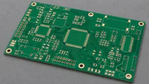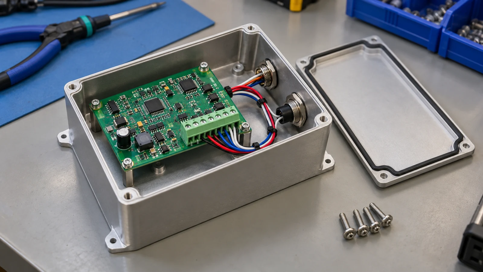
PCBA vs box build is a choice about the physical product an OEM receives. Choose PCBA when the supplier delivers an assembled board and the OEM retains product integration. Choose box build when the supplier must integrate that board with the specified cables, enclosure and other parts, then release the agreed assembly. For finished-product orders, use 100% execution of the agreed final acceptance sequence, linked to each product serial number, as a procurement benchmark. Define the shipped configuration before comparing prices: the words “box build” alone do not specify it.
| Your project needs | Preferred scope | Responsibility that decides the choice |
|---|---|---|
| Boards for an established OEM integration line | PCBA | OEM installs, configures and releases the product |
| Configured units ready for the agreed pack-out | Box build | Supplier integrates and verifies the specified product |
| Frequent enclosure changes during development | PCBA | OEM retains access and controls mechanical iterations |
| Integration of an already approved board design | Box build | Supplier owns the agreed assembly and final test operations |
- PCBA and Box Build Deliver Different Physical Products
- Cables, Harnesses and Connectors Beyond the Board
- Enclosures, Fasteners and Mechanical Work Instructions
- Firmware, Configuration and System-Level Testing
- Separate loading from developing firmware
- Define a measurable product test
- Labels, Accessories and Finished-Product Packaging
- Where PCBA Wins and Where Box Build Wins
- Where PCBA wins
- Where box build wins
- An Acceptance Boundary for Board-Level and Product-Level Orders
- Final Recommendation: Define the Shipped Item First
PCBA and Box Build Deliver Different Physical Products
A printed circuit board assembly, or PCBA, is a board with mounted and electrically connected components. A box build combines PCBAs with the other items needed to create a specified assembly. That assembly might be an enclosed controller, a front-panel module or a finished instrument. Its part number, drawing and acceptance plan define where delivery ends.
A PCBA can include soldered connectors, wire leads, programming and board functional testing when those operations appear in the order. It can still leave enclosure installation and product acceptance with the OEM. Name the shipped item precisely. If a box-build order stops at a prewired front-panel module that another plant will install in a machine, that module is the delivery boundary even though the surrounding machine remains unfinished.
Use the following matrix to compare the same product revision. The OEM approves requirements; the assigned supplier executes and records its release checks.
| Deliverable | PCBA Scope | Box-Build Scope | Required Input | Acceptance Owner |
|---|---|---|---|---|
| Board assembly | Populate and solder the board; inspect and test to the board plan | Include or receive the approved PCBA and preserve its revision identity | Board BOM, placement data, assembly drawing and board test plan | OEM electronics owner approves; PCBA supplier releases the board |
| Cable integration | Fit board connectors and any specifically ordered leads | Install, route, secure and mate specified cables or harnesses | Harness drawing, pin-to-pin netlist, connector parts and routing instructions | OEM interconnect owner approves; assigned integrator verifies installation |
| Enclosure installation | Supply the board with defined mounting interfaces | Mount the board, panels, hardware and specified enclosure parts | Mechanical BOM, assembly drawing, fastener and joint instructions | OEM mechanical owner approves; box-build supplier verifies assembly |
| System configuration | Load a board image or board settings when ordered | Apply released firmware, product options and calibration data | Approved software release, configuration map and programming procedure | OEM software owner approves; executing supplier records loaded configuration |
| Product testing | Verify the board against its board-level limits | Exercise the agreed finished assembly and external interfaces | Product test specification, fixtures, loads, limits and record format | OEM product/quality owner approves; box-build supplier executes release tests |
| Final packaging | Protect and identify boards for the next assembly stage | Pack the defined product, accessories, labels and documents | Packaging BOM, label artwork, accessory list and pack-out instructions | OEM quality/logistics owner approves; packing supplier verifies contents |
Board documentation remains necessary in either route. The Eurocircuits assembly guidelines identify BOM/CPL data, component orientation and clearances as distinct assembly topics. Box-build drawings add the interfaces around that board; they do not replace the board release package.
Component purchasing is a separate decision. Either physical delivery scope can use an agreed customer-supplied or supplier-sourced material arrangement.
Cables, Harnesses and Connectors Beyond the Board
Cable integration belongs to the scope that makes and verifies the connections between the board and the rest of the product. A soldered board header does not establish responsibility for its mating plug, crimp contacts, cable length or routing. Assign those items by part number and operation before accepting a quotation.
The OEM normally supplies or approves the harness definition. If a supplier develops it, include that engineering work explicitly and require an OEM release before production. Release the drawing, not just a sample. A photograph helps explain routing, but the controlled drawing must identify connector views, cavity numbers, wire sizes, insulation, lengths, tolerances, shields and strain relief so both suppliers build and inspect the same interface.
For example, a drawing might connect J1 cavity 1 to J3 cavity 4. Showing whether each connector is viewed from the mating face or wire-entry side prevents a mirrored pinout. Record where a shield drain terminates and whether it connects to chassis or circuit ground. Those are electrical design decisions.
The acceptance checks should cover connector seating, latch engagement, terminal retention and routing clearances alongside the specified electrical tests. Check hidden joints before closure. Where mating connectors can be interchanged, require an identity or pinout check that distinguishes them; a seated latch proves engagement, but it cannot prove that the correct plug reached the correct socket. Repeat affected interface checks after installation because closure can pinch a previously tested harness.
For resistance testing, the relevant measurement choices are two-wire and four-wire. Two-wire measurements include fixture and lead resistance; four-wire measurements separate current and voltage connections to reduce that influence. The Cirris resistance calculator accounts for conductor geometry, temperature, contacts, fixturing and instrument accuracy. Use those inputs to establish the particular circuit’s threshold in ohms. A continuity indication alone does not demonstrate signal integrity or operation at the rated load.
Enclosures, Fasteners and Mechanical Work Instructions
Box build includes enclosure installation only to the extent defined in the assembly order. The housing can be purchased, supplied by the OEM or procured from an approved mechanical vendor. Making the housing is a separate deliverable. The assembly supplier needs released instructions for fitting it around the electronics.
The mechanical package should identify the enclosure revision, mounting datums, standoff heights, fastener part numbers, engagement lengths, washers and tightening sequence. Specify cable capture points and the installed condition of gaskets, thermal pads and insulating barriers. These details determine whether the working board survives installation and whether external connectors remain accessible.
Torque belongs to a particular joint. Identify the complete joint stack. The work instruction needs the screw, mating material or insert, lubrication or threadlocker condition, target and permitted interval in N·m, tool requirements and rework method, because a nominal screw size does not describe those interacting conditions.
Two manufacturer examples show why:
- The Phoenix Contact MSTB 2,5/ 2-ST-5,08 BD IN 5, part 1705986, specifies 0.5–0.6 N·m for its terminal screw connection and a 7 mm stripping length. Those values address that conductor termination. Phoenix Contact product data.
- The Hammond 1590BSFL drawing recommends 50–55 cN·m for the standard cover and 25–30 cN·m with the specified gasket arrangement. Converted to N·m, these are 0.50–0.55 N·m and 0.25–0.30 N·m respectively. The gasket changes the instruction. Hammond enclosure drawing.
Do not transfer either interval to another joint. A high-assurance assembly plan uses the correct controlled setting, rather than the largest available number. Keep the tool’s operating tolerance inside the permitted process window established for that joint.
Assign verification for board support, cable pinching, gasket seating and closure before final test. Inspect before access disappears. A torque witness mark identifies a marked joint; it does not measure the torque applied. Where the acceptance plan requires fastening records, distinguish the tool setpoint from a measured result and link the required record to the assembly.
Firmware, Configuration and System-Level Testing
Box-build acceptance must verify the agreed product configuration and the functions affected by integration. A passing board test cannot cover a cable, display, power supply or enclosure arrangement that was absent from that test. Keep the board test as an intermediate release gate, then add product checks through the relevant external interfaces.
Separate loading from developing firmware
Identify the released binary, its verification method, compatible hardware revision and configuration file. Assign programming, calibration, option selection and readback to named operations. Firmware development and debugging need their own scope; ordering a programmed assembly does not automatically include either.
Configuration must be reproducible. Record the loaded revision and product options against the finished-unit serial number. A successful programming message is only one check. If temporary test firmware or test-mode settings are used during assembly, the route must restore and verify the released shipping configuration before the final product is accepted.
Define a measurable product test
A system test specification needs stimuli, measurement points, connected loads, operating modes, environmental conditions and pass/fail rules. Name the measurement point. A voltage measured at an internal board pad does not include the drop across a production harness and connector, so a requirement for voltage at the external port must be verified at that port. Include fixture revision, instrument accuracy, stabilization time and failure disposition.
NI’s discussion of production testing for complex devices describes how added functions broaden test coverage requirements. For a box build, map that coverage to the installed interfaces: a keypad command, a display response, a communications transaction or an output under load.
This illustrative controller requirement shows the necessary specificity. Its values belong to the example product, not to box builds as a category.
| Illustrative controller test input | Defined requirement |
|---|---|
| Physical configuration | Housing closed; production harness fitted; released production firmware loaded |
| Supply | 24.0 V DC measured at the product inlet |
| Load | 0.50 A drawn from the external regulated output |
| Ambient condition | 23 ± 2 °C |
| Timing | Measure after 10 s stabilization |
| Product output tolerance | 5.00 V nominal, ±5%; engineering limits 4.75–5.25 V |
| Record | Product serial number, firmware/configuration revision, measured output and disposition |
The real test plan must translate its engineering limits into tester limits using the agreed measurement uncertainty and any guard band. It must also define functions beyond this single voltage measurement. Thermal qualification, electrical safety and environmental validation require their own product-specific plans; a short functional check cannot replace them.
For the defined finished-product route, specify the agreed final acceptance sequence on 100% of units and retain a result for each serial number. This controls execution coverage. It does not mean every possible failure mechanism has been tested.
Labels, Accessories and Finished-Product Packaging
Finished-product delivery includes the identity, accessories and packaging specified for that product. A tested enclosed unit is incomplete when its ordered cable, mounting kit or required label is missing. Define pack-out as a controlled assembly operation with its own bill of materials and release check.
Use a product serial number for the finished assembly and preserve the board identity beneath it. Link the records. When board-level traceability is required, the product record should identify the installed PCBA serial number and any replacement, allowing a service team to find the relevant board, product configuration and final test result from the external label.
Release label artwork, placement, revision rules and barcode content with the product documentation. Assign any required markings through the OEM’s approved product requirements. Printing a symbol does not establish that the product qualifies to carry it.
For PCBA orders, packaging protects and identifies boards for the next operation, including the specified ESD protection. For box build, the packaging BOM can add port protection, display films, accessories, instructions and the shipping container. State which items are installed, packed loose or supplied separately.
Scan before packing. At pack-out, reconcile the unit identity, accessory quantities and packaging revision, and reject a mismatch between the label and the released configuration even when the electronics passed their functional test. Any required shipment test needs its own packaged configuration and acceptance procedure.
Where PCBA Wins and Where Box Build Wins
PCBA wins when the OEM benefits from controlling the remaining integration work. Box build wins when a defined product configuration can be transferred with its assembly instructions and acceptance tests. Compare the same outcome. A quotation for a populated board and a quotation for a packed product include different operations, so the commercial comparison must add the work retained by the OEM before either route can be judged cheaper.
Where PCBA wins
Established integration capacity. An OEM with trained assemblers, fixtures and a functioning product-test station can buy accepted boards and use that existing capacity. This is especially useful when one board serves several enclosures or accessory combinations. The OEM retains responsibility for cable installation, mechanics, configuration and final release, and includes those operations in its cost comparison.
Development access. A project with frequent changes to mounting points, displays or cable routing can keep product assembly close to its design team while ordering boards to a controlled electronics revision. The benefit is access to the unfinished product for iteration. Once the configuration stabilizes, the same documentation can support a later box-build quotation.
Where box build wins
Repeatable finished configurations. A released enclosure, harness set and firmware configuration allow the supplier to repeat a defined assembly route. The supplier can coordinate checks before closure and execute the final test in the agreed configuration. The OEM receives the specified assembly and its release records, reducing the number of remaining internal production operations.
Limited internal integration capacity. An OEM without an established assembly and product-test line can include that work in a box-build order. The useful deliverable is an integrated, accepted unit with documented contents. Assign fixture ownership early. The quotation should state who develops the fixture, who approves its coverage and who maintains it when the product revision changes.
There is no universal order quantity at which box build becomes the better choice. Compare material, assembly, fixtures, test time, internal handling, rework and packaging for the same released configuration and batch quantity.
An Acceptance Boundary for Board-Level and Product-Level Orders
The acceptance boundary is the point where a defined physical assembly, its approved configuration and its required records transfer to the next owner. Write that boundary into the quotation and purchase order. A single supplier can provide both scopes, but each scope needs an identifiable release gate.
A practical delivery flow is:
Released board files → PCBA assembly and board checks → PCBA delivery gate → cable and enclosure integration → product configuration and final checks → labels, accessories and packaging → finished-product delivery gate
A box-build supplier may receive an already accepted PCBA at the first gate. Define incoming identity, handling-damage checks and any repeat tests before integration begins. Board acceptance and product acceptance then remain traceable even when different suppliers perform them.
| Project constraint | Preferred scope | Condition to write into the order |
|---|---|---|
| OEM retains a qualified product integration line | PCBA | Supplier releases boards; OEM owns installed-product acceptance |
| Mechanical design is still changing frequently | PCBA | Freeze the board revision and keep mechanical iteration with the OEM |
| Product must arrive configured and packed | Box build | Define exact firmware, accessories, labels and packaging BOM |
| Failures occur mainly at installed interfaces | Box build | Include post-installation checks for cables, connectors and external functions |
| One board supports several product variants | PCBA or box build by variant | Use separate product BOMs and configuration rules; retain board-to-product identity |
| Serial-linked finished-unit release is required | Box build, or PCBA plus OEM final assembly | Name the operator of the 100% final acceptance sequence and owner of its records |
Before awarding the order, close three practical questions. Which released part number ships? Which checks authorize shipment? Who approves an exception? Record the answers with the applicable BOM, drawing and test-plan revisions so an accepted board cannot be mistaken for an accepted finished product simply because both came from the same factory.
The OEM design owners should approve technical requirements and changes. Supplier manufacturing and quality teams execute the agreed operations and retain the specified records. Define access to those records, including which measured values accompany shipment and which remain available from the supplier. Name the OEM authority that can approve a deviation. Hold nonconforming units for authorized disposition, and repeat affected checks after repair, board replacement or configuration changes.
For comparable quotations, request a board-only price and the incremental integration work against the same board revision. Separate one-time fixtures or programming setup from recurring assembly, testing and pack-out. Quote enclosure manufacture separately if required. This makes the physical delivery change visible without treating a lower board price as a lower finished-product cost.
Frequently Asked Questions
The PCBA versus box-build decision is settled by the shipped item, the remaining integration work and the agreed release checks. These answers address the responsibilities that most often need clarification before an OEM accepts a quotation.
Does box build always include manufacturing the enclosure?
No. Box build can use an enclosure supplied by the OEM, purchased as a standard part or made by a separate mechanical supplier. The order must distinguish housing procurement or manufacture from installing the electronics, cables, panels and hardware inside it.
Who supplies cable and harness drawings?
The OEM normally supplies or approves cable and harness drawings. Supplier development can be commissioned separately. Before production, the released drawing must identify connector parts, cavity views, pinout, wire specification, lengths, routing and acceptance criteria so the harness maker and final integrator use the same definition.
Is board-level functional testing enough for box build?
No. Board-level functional testing covers the board in its test setup, while box-build acceptance must address the installed assembly. Add the agreed checks for cables, external interfaces, product configuration and functions affected by integration, then link the final result to the finished-unit identity.
Should serial numbers identify the board or the finished product?
A finished-product serial number should identify the shipped assembly, with the board serial number linked beneath it when board-level traceability is required. PCBA-only orders can use board identities. Preserve the relationship after board replacement so test and service records continue to identify the correct configuration.
Can the same supplier quote PCBA and box build separately?
Yes. Keep the board revision identical. Request a board-only quotation and a separate integration quotation that identifies the added cables, enclosure, configuration, product testing and packaging, with one-time fixture costs separated from recurring unit costs so both routes can be compared at the same delivery boundary.
Does box build include firmware development?
No. Loading an approved firmware image and developing that firmware are separate tasks. Specify the released binary, compatible hardware, product options, programming verification and records for the assembly order. Include software development or debugging only when those activities are explicitly assigned.
Can an OEM start with PCBA and move to box build later?
Yes. An OEM can integrate early boards internally, then transfer a stable product configuration into box build. The transfer needs released mechanical and harness drawings, configuration rules, assembly instructions, fixtures and a product acceptance plan, followed by an agreed initial-build review.
What files are needed for a box-build quotation?
Provide the board package plus the product BOM, enclosure and harness drawings, mechanical work instructions, firmware/configuration requirements, final test specification, label artwork, accessory list and packaging instructions. State the shipped part number and revision, quantities, supplied materials and responsibility for releasing the finished assembly.
Final Recommendation: Define the Shipped Item First
Choose PCBA when the OEM will own the remaining integration and finished-product release. Choose box build when the supplier will deliver the defined assembly with its specified configuration, checks and pack-out. Put that distinction into the RFQ before requesting a price.
Start with the product BOM. Mark the operations that stop at the board, continue through integration and authorize shipment, then attach the test inputs and limits, mechanical instructions, serial-number rules and packaging definition so the quotation assigns acceptance owners at both delivery gates.
For a JASPER enquiry, use the PCB assembly services route and include enclosure, cable and interface requirements when integration is part of the project. Request both scopes explicitly. Each quotation should identify the shipped assembly and the work that remains with the OEM.
Ready to Start Your Project?
Tell us about your membrane switch, keypad, or graphic overlay requirements. Our engineering team will review your specifications and provide a detailed quote.