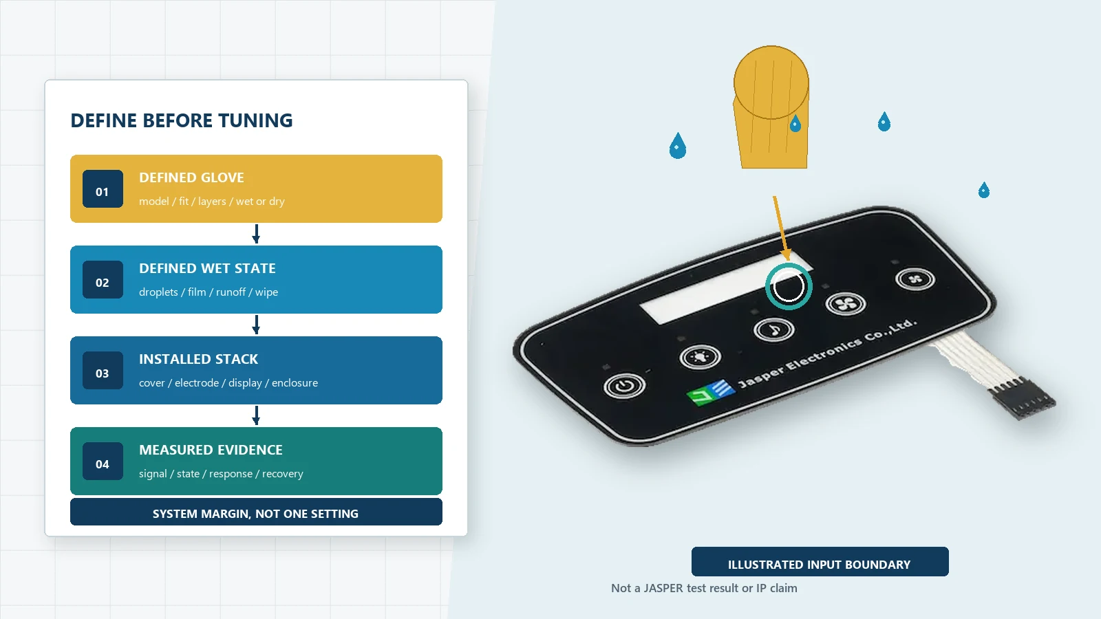
Design capacitive touch for water and gloves by defining the required wet and
gloved behaviors before selecting electrodes or controller settings. Specify the
actual glove, cover stack, touch target, water state, enclosure, display, ground,
and acceptance criteria. Then build enough signal margin for valid touches while
rejecting droplets, films, runoff, wipes, sleeves, palms, and recovery transients.
There is no universal glove mode or waterproof tuning value. The approved
design is the complete installed system, including sensor geometry, cover,
controller, firmware, shielding, drainage, feedback, and validation.
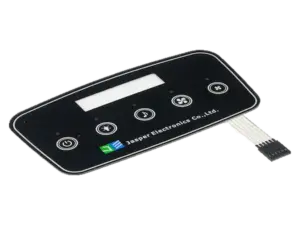
JASPER’s custom capacitive touch
panels can combine
a printed or rigid front, capacitive sensor, PCB/FPC, display window, lighting,
connector, adhesive, gasket, and front-panel assembly. The OEM still needs to
define the controller, glove set, wet states, enclosure, host behavior, and final
equipment validation unless those responsibilities are explicitly included in
the quotation.
- Water and Gloves Are Requirements, Not Feature Names
- Define the Behavior Before the Hardware
- Use a Signal-Margin Model
- The Cover Stack Sets the Glove Problem
- Freeze the Real Cover, Adhesive, and Air-Gap Stack
- Electrode Size, Shape, Pitch, and Routing
- Ground, Shield, Guard, Display, and Enclosure Must Be Reviewed Together
- Ground reference
- Rear shield
- Guard channel or guard electrode
- Enclosure and drainage
- Distinguish Moisture Tolerance From Spill Rejection
- Build a Water-State Library
- Condensation
- Isolated droplets
- Thin film
- Wet finger
- Wet glove
- Runoff
- Pooling
- Cleaning wipe
- Drying and residue
- Define Every Glove as a Controlled Test Article
- Controller Tuning Is a State-Management Problem
- Baseline too fast
- Baseline too slow
- Threshold too low
- Threshold too high
- Filtering too aggressive
- Mode switching without evidence
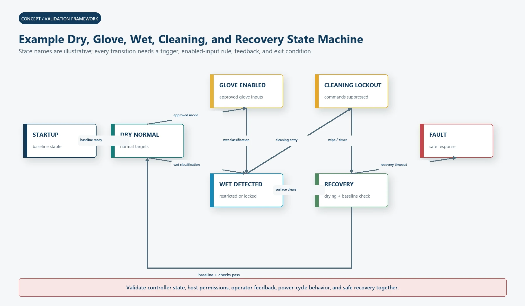
- Use an Explicit State Machine
- Feedback Matters More When Sensitivity Is Conditional
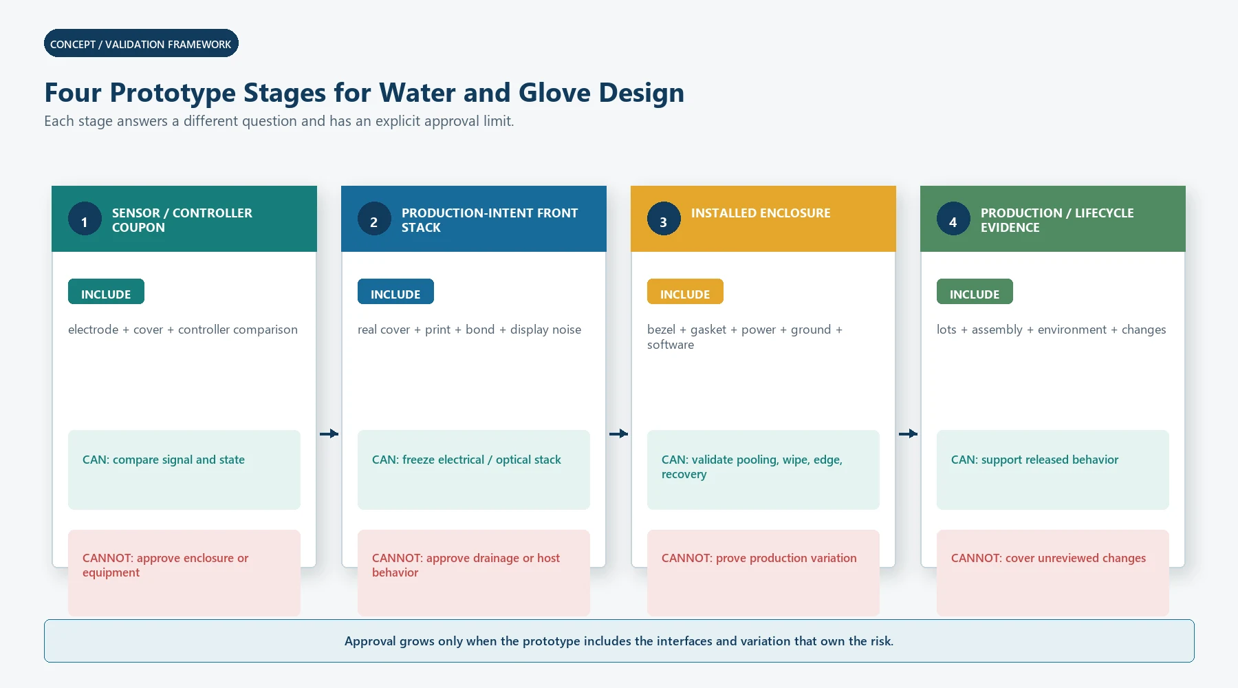
- Prototype in Four Stages
- Stage 1: Sensor and controller coupon
- Stage 2: Production-intent front stack
- Stage 3: Installed enclosure prototype
- Stage 4: Production and lifecycle evidence
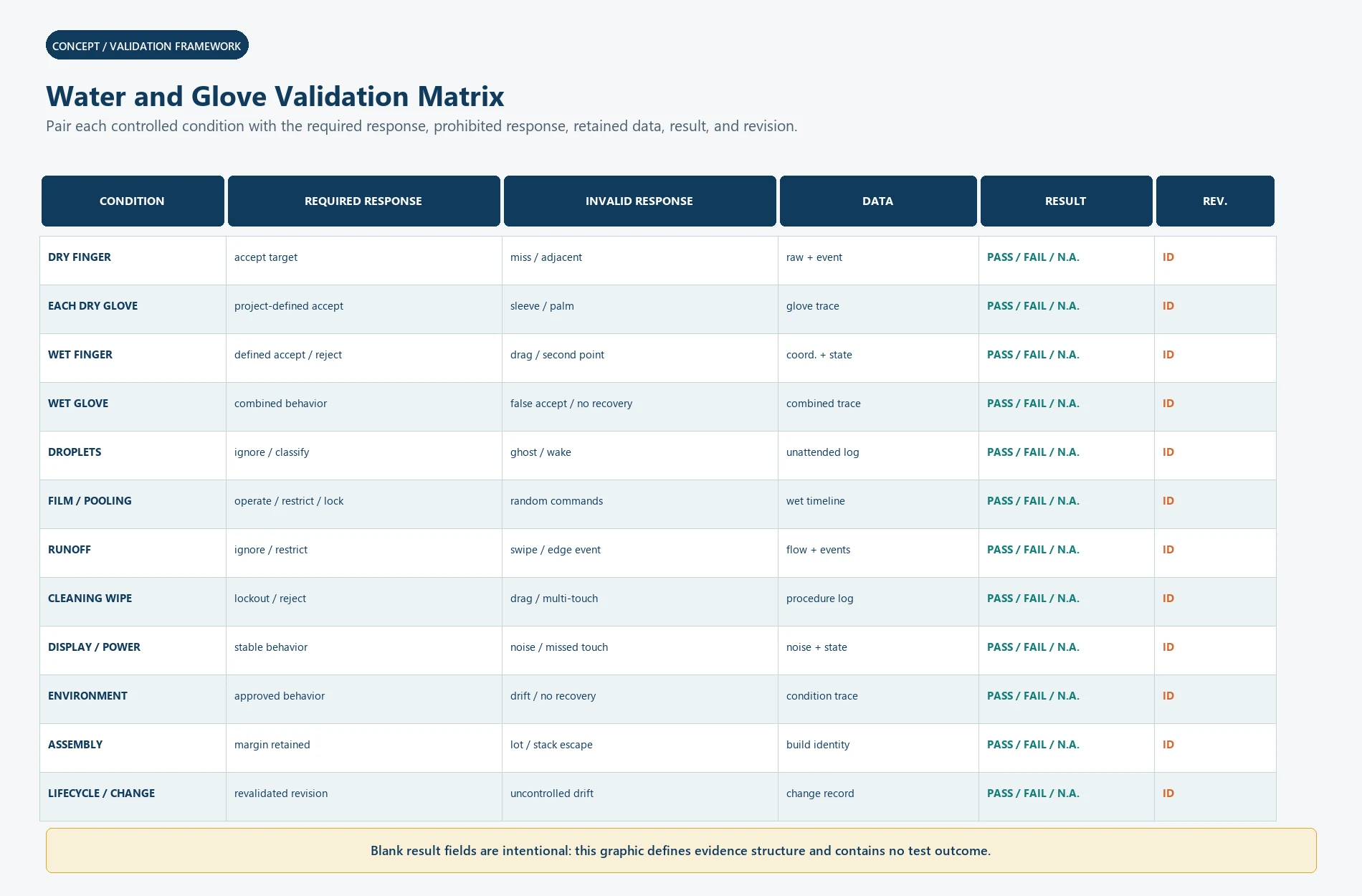
- Water and Glove Validation Matrix
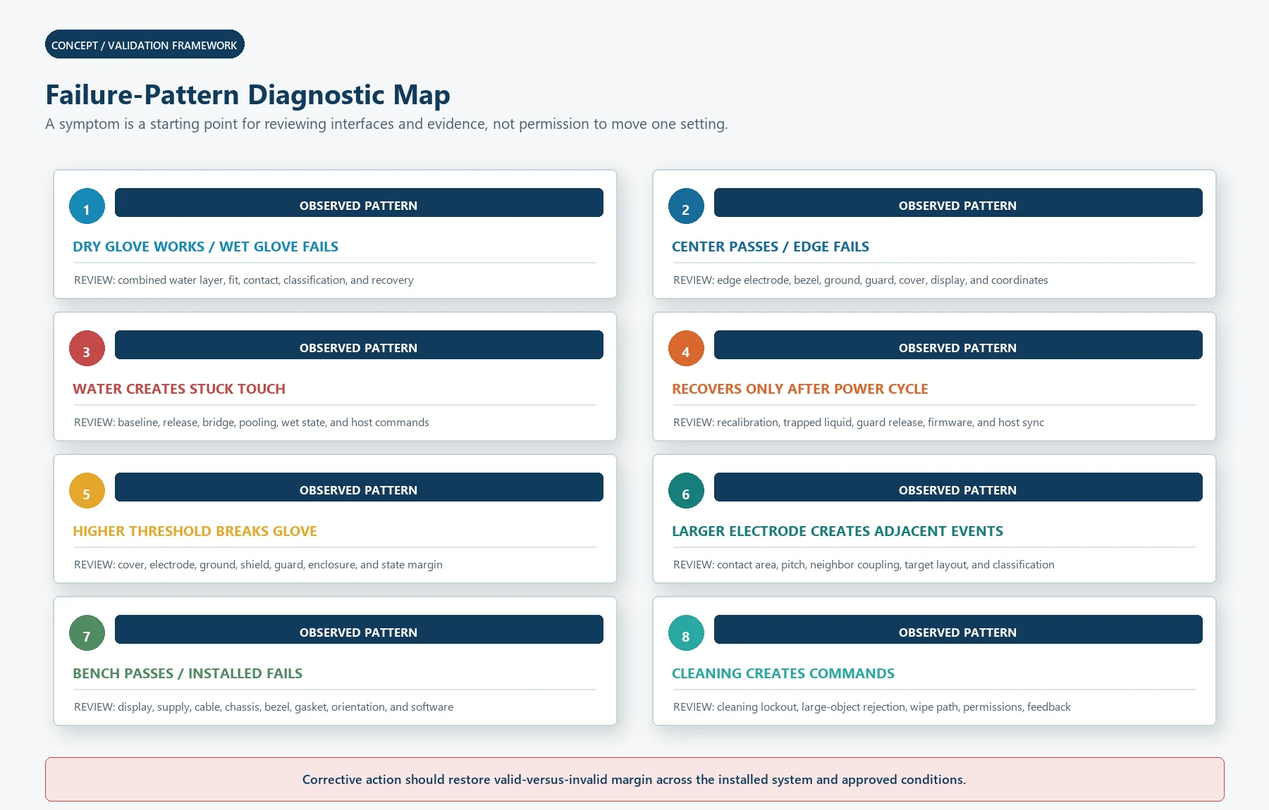
- Common Failure Patterns
- Dry glove works, wet glove fails
- Center targets work, edge targets fail
- Water causes a stuck touch
- The panel recovers only after power cycling
- A higher threshold fixes water but breaks gloves
- A larger electrode fixes gloves but creates adjacent events
- Bench testing passes, installed equipment fails
- Cleaning creates commands
- Manufacturing and Change Control
- Stop Conditions Before Release
- OEM Input Checklist
- Send the Real Glove, Cover, and Wet-State Requirements
- Sources
Water and Gloves Are Requirements, Not Feature Names
Works with gloves is incomplete. It could mean:
- one specified dry nitrile glove;
- two layers of a medical glove;
- a loose work glove;
- an insulated winter glove;
- a glove contaminated with oil or dust;
- a wet glove;
- a glove used with a fingernail or fingertip pad;
- or an operator pressing at an angle while moving.
Works when wet is equally incomplete. It could mean:
- accept a wet finger on an otherwise dry surface;
- ignore isolated droplets;
- continue normal use under a thin film;
- reject all touches while a spill is present;
- accept only selected controls during rain;
- tolerate moving runoff;
- ignore a cleaning wipe;
- recover automatically after drying;
- or survive ingress testing without operating during the exposure.
Each statement creates a different sensor, controller, software, enclosure, and
validation problem.
Define the Behavior Before the Hardware
Start with a state table.
| Surface and input state | Required response | Invalid response to prevent | Evidence |
|---|---|---|---|
| Dry surface, bare finger | Accept intended targets | Missed touch, adjacent target, edge error | Installed coordinate and event log |
| Dry surface, specified glove | Accept intended targets | Sleeve, palm, hover, adjacent target | Glove-specific test result |
| Wet finger, dry surface | Project-defined accept or reject | False release, drag, second point | Coordinate and state trace |
| Droplets, no user | Ignore | Ghost touch or wake event | Timed unattended exposure |
| Water film, no user | Continue, lock out, or enter wet mode | Random coordinates or repeated commands | Wet-state log |
| Water film plus bare finger | Project-defined behavior | Wrong target, stuck touch, unintended gesture | Combined-condition test |
| Water film plus glove | Project-defined behavior | False acceptance or non-recovery | Combined-condition test |
| Moving runoff | Ignore or restrict operation | Swipes, edge touches, wake events | Flow direction and rate recorded |
| Cleaning wipe | Lock out or reject | Drag, multi-touch, repeated commands | Cleaning procedure test |
| Surface drying | Recover within approved behavior | Touch during unstable baseline, permanent lockout | Recovery trace |
Do not start by asking a controller supplier for more sensitivity. First decide
which cells in this table must pass and which must be rejected.
Use a Signal-Margin Model
A capacitive controller makes decisions from measured changes. The useful touch
signal must remain distinguishable from baseline movement, noise, water,
enclosure coupling, display interference, component variation, and invalid
objects.
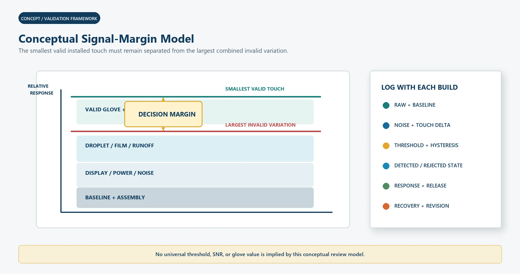
A practical conceptual model is:
usable decision margin
    = smallest valid touch signal
    - largest combined baseline, noise, water, and assembly variation
This is not a controller formula. It is a review rule.
Texas Instruments describes capacitive-touch sensitivity in terms of signal,
noise, and SNR, and recommends designing with enough margin for noise, voltage,
temperature, and manufacturing variation.[8] A large raw-count change on one
bench unit is not sufficient. The important quantity is the smallest valid
installed touch compared with the largest invalid change across the approved
conditions.
For each prototype, log:
- raw sensor data where available;
- baseline or reference;
- touch delta;
- noise in the relevant operating state;
- controller threshold and hysteresis;
- detected state;
- rejected state;
- wet or guard state;
- coordinate and target;
- time to detect;
- time to release;
- time to recover;
- firmware and configuration revision; and
- cover, sensor, display, enclosure, glove, and water condition.
Without that trace, tuning becomes a sequence of impressions rather than an
engineering decision.
The Cover Stack Sets the Glove Problem
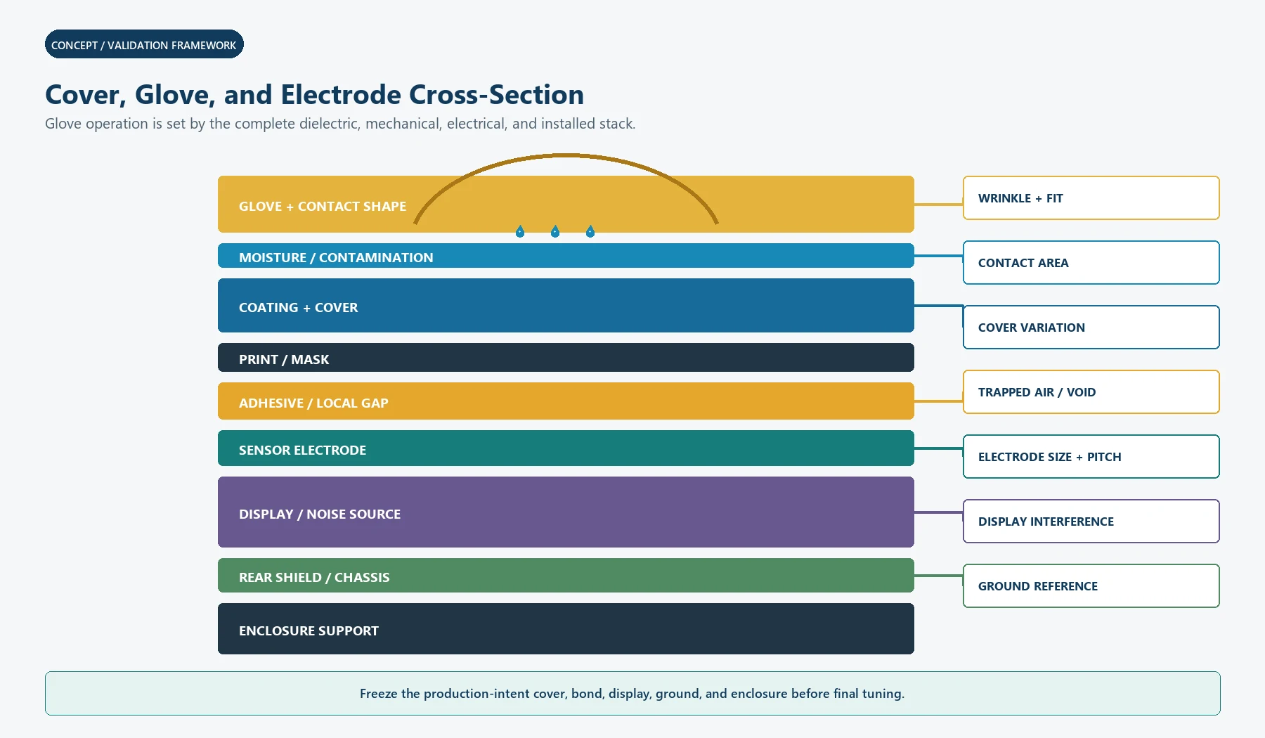
The operator does not touch the electrode directly. The electric field crosses:
- surface coating;
- cover lens or graphic front;
- printed ink or mask;
- adhesive or optical material;
- air gaps or local voids;
- sensor carrier;
- and any other dielectric separation in the real stack.
Microchip AN2934 treats touch-cover properties, thickness, contact, air gaps, and
sensor design as linked inputs.[6] TI also notes that overlay material and
thickness affect sensitivity and that air gaps can reduce coupling.[8]
Add a glove and the field must cross another material layer. The result depends
on:
- glove material;
- glove thickness;
- number of layers;
- fit and wrinkles;
- trapped air;
- moisture or contamination;
- fingertip geometry;
- operator posture;
- contact area;
- cover surface;
- target size;
- and controller method.
Pressing harder may compress a soft glove or increase contact area, but PCAP is
not measuring force. Do not convert operator can make it work by pressing hard
into a reliable glove requirement.
Freeze the Real Cover, Adhesive, and Air-Gap Stack
A tuning sample should use the production-intent stack.
Record:
- Cover material, supplier, grade, thickness, coating, finish, curvature, and
print. - Ink and mask layers in the active and border regions.
- Adhesive or optical material, thickness, bond coverage, and cure condition.
- Allowed air gaps, bubbles, voids, steps, and local thickness changes.
- Sensor substrate and electrode-to-cover registration.
- Display, polarizer, bezel, metal, and PCB positions.
- Ground, shield, chassis, cable, and connector configuration.
- Enclosure support, fasteners, gasket, and compression.
Changing from a taped bench coupon to a bonded production cover can change the
signal. So can a new print stack, coating, adhesive lot, display, bezel material,
or enclosure ground.
JASPER’s existing capacitive touch switch
guide
provides broader cover, sensor, ground, LED, moisture, and enclosure context. This
Blog stays narrow: how those inputs affect water and glove operation.
Electrode Size, Shape, Pitch, and Routing
Electrode geometry must serve the actual input object and interface.
Review:
- target size shown to the user;
- electrode size behind the target;
- finger and gloved fingertip area;
- spacing and pitch between adjacent targets;
- border and edge electrodes;
- sliders, wheels, or coordinate matrix geometry;
- trace length and routing;
- trace proximity to LEDs, display, power, chassis, and ground;
- tail and connector coupling;
- and inactive areas that can still receive water or a palm.
TI’s design guide states that electrode size affects sensitivity and should be
related to the intended touch contact rather than enlarged without limit.[8]
Oversizing can increase unwanted coupling, neighboring interaction, and
environmental response. Undersizing can leave too little signal after the cover
and glove are added.
For a button interface, define whether a droplet bridging a key and nearby guard,
ground, or another key should cause:
- no event;
- a wet-state event;
- a global lockout;
- a local lockout;
- or a restricted mode.
For a coordinate panel, define:
- edge behavior;
- large-object rejection;
- palm and sleeve behavior;
- multi-touch behavior;
- wet-finger tracking;
- gesture enablement;
- and whether the display should remain interactive during a wet state.
Button-guard strategies do not automatically transfer to every PCAP matrix.
Ground, Shield, Guard, Display, and Enclosure Must Be Reviewed Together
Ground and shielding can improve one problem while reducing touch signal or
creating another coupling path.
TI notes that nearby ground increases parasitic capacitance and can reduce
sensitivity, while a shield behind the sensor can reduce influence from the rear
side.[8] Microchip AN2934 likewise treats shielding and sensor layout as
application-dependent.[6]
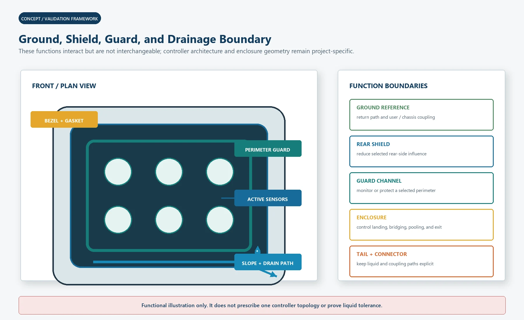
Separate these functions:
Ground reference
Defines the electrical reference and return path for the controller, host,
display, chassis, and user coupling. A ground plane placed close to an electrode
can reduce sensitivity.
Rear shield
Can reduce influence from displays, batteries, cables, metal, or other rear-side
objects. Whether it is grounded, driven, patterned, or omitted depends on the
controller and stack.
Guard channel or guard electrode
Can monitor liquid or protect the perimeter in selected architectures. TI
describes guard-channel spill rejection that can lock out touch channels when a
spill is detected.[8] TI’s TIDM-1021 reference design also demonstrates that
liquid tolerance is a combined hardware and software function.[9]
Enclosure and drainage
Controls where water lands, bridges, pools, runs, and exits. Surface angle,
recesses, bezels, seams, gasket paths, fasteners, and tail exits can change both
the liquid pattern and the electric environment.
Do not add a guard ring after the enclosure is complete and assume the water
problem is solved. The guard, cover, sensor, controller, bezel, drainage, and wet
behavior must be designed as one boundary.
Distinguish Moisture Tolerance From Spill Rejection
TI separates two common goals:[8]
- moisture-tolerant operation, where intended touches remain detectable under
limited moisture; and - spill rejection, where the system detects a spill and prevents normal touch
events.
These goals can conflict.
High sensitivity that helps a thick glove may also make the system more
responsive to water, sleeves, palms, edge contact, or environmental variation.
A wet-mode lockout can prevent false commands but may make the product unusable
until recovery. A guard that detects a large spill may not classify every small
droplet or wet finger correctly.
Choose a behavior:
| Wet requirement | Controller/system direction | Main tradeoff |
|---|---|---|
| Ignore droplets and keep normal operation | Preserve valid-touch margin while rejecting small moisture changes | Harder when glove signal is already small |
| Accept wet-finger touches | Separate intended touch from added water coupling | Wet finger may create a different signal and contact shape |
| Reject operation under a film | Detect wet state and lock or restrict inputs | Recovery and user feedback become critical |
| Allow selected controls only | State machine and target-level permissions | More software and validation combinations |
| Enter cleaning mode | Deliberate UI state, timer, or physical control | Must prevent accidental entry or exit |
| Survive washdown without operation | Enclosure and post-exposure function | Not evidence of usable touch during washdown |
Never compress this table into waterproof touch.
Build a Water-State Library
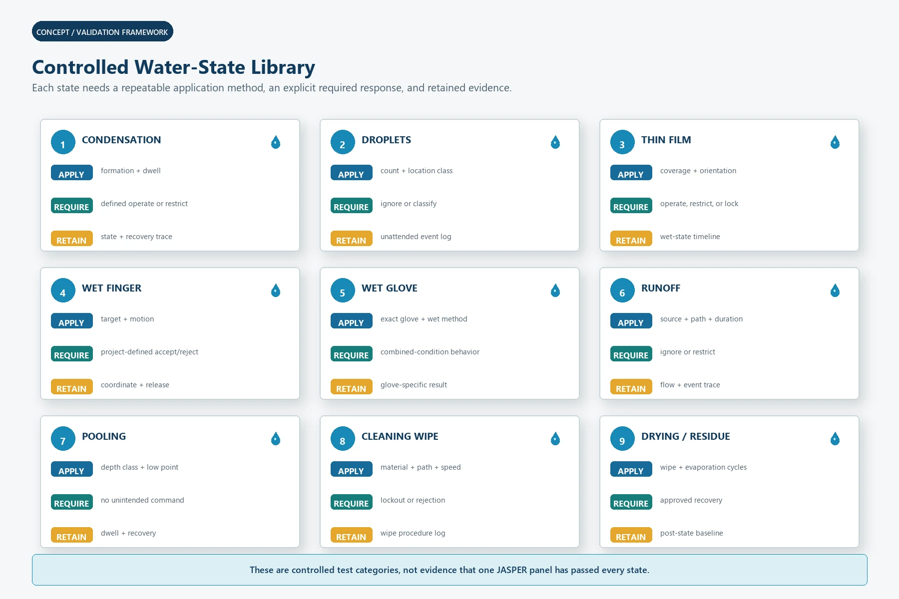
Use controlled water states, not one spray bottle test.
Condensation
Fine droplets can form gradually and may not behave like a poured spill. Test
formation, dwell, coalescence, user contact, and recovery.
Isolated droplets
Record location, size class, count, active/inactive area, border proximity, and
whether droplets bridge electrodes, guard, ground, mask, or bezel.
Thin film
Define how the film is applied, its coverage, whether it is continuous, and
whether the surface is horizontal, tilted, or vertical.
Wet finger
Test the intended finger movement and target. A wet finger can change both
coupling and contact footprint. Include touch, release, drag, and repeated input.
Wet glove
Treat this as a separate condition, not the sum of a dry-glove test and a
wet-finger test. Water may enter the glove, coat its surface, bridge wrinkles, or
change the contact area.
Runoff
Control source, direction, path, duration, and whether it crosses the border,
display, keys, guard, seams, or cable exit.
Pooling
Review enclosure recesses and low points. A design that passes with moving runoff
may fail when liquid remains over the active area or bezel.
Cleaning wipe
Use the real wipe material, fold, pressure, speed, path, liquid, and cleaning
procedure. A wipe can look like a large moving finger or multi-touch object.
Drying and residue
Test recovery after evaporation, wiping, residue, repeated cycles, and power
interruption. The surface may look dry while the bezel, edge, or bond region
remains wet.
Define Every Glove as a Controlled Test Article
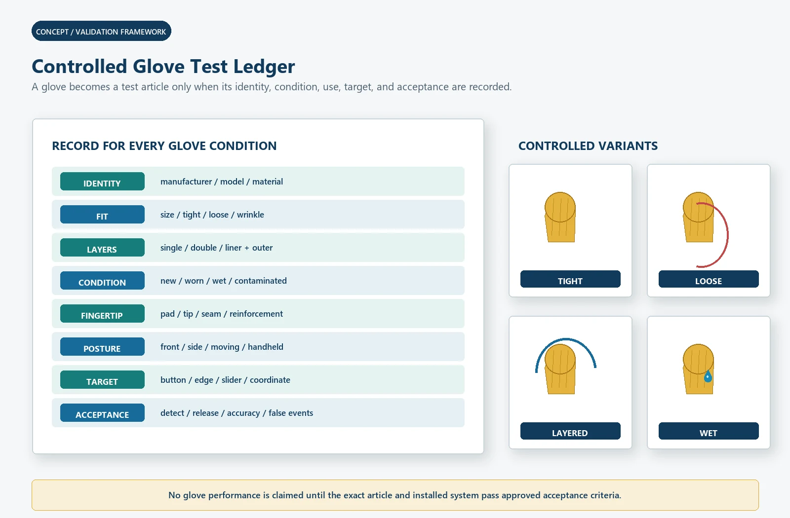
Create a glove ledger.
| Glove input | What to record |
|---|---|
| Manufacturer and model | Exact commercial glove or controlled material |
| Material | Nitrile, latex, vinyl, textile, coated fabric, insulated construction, or other |
| Size and fit | Tight, loose, wrinkled, oversized, or layered |
| Layers | Single, double, liner plus outer glove, or other |
| Condition | New, worn, wet, contaminated, cold, warm, or aged |
| Fingertip geometry | Flat pad, tip, seam, reinforcement, coating, or fold |
| Operator posture | Front, side, reach, moving, supported, or handheld |
| Target | Button, edge key, slider, wheel, coordinate area, or gesture |
| Acceptance | Detection, target accuracy, release, repeatability, feedback, and false-event limits |
Do not approve nitrile glove based on an unnamed sample from a desk drawer.
Different thickness, fit, layers, surface treatment, moisture, and finger posture
can change the result.
Test:
- smallest approved fingertip contact;
- largest approved contact;
- center and edge targets;
- quick tap;
- dwell;
- drag;
- repeated touch;
- adjacent-target transitions;
- multi-touch if required;
- wet glove;
- cold or warm state if relevant;
- and invalid sleeves, palms, knuckles, and tools.
Controller Tuning Is a State-Management Problem
Typical configuration areas can include:
- baseline update;
- touch threshold;
- release threshold;
- hysteresis;
- debounce;
- filtering;
- scan frequency;
- frequency hopping or noise handling;
- electrode grouping;
- gain or sensitivity;
- glove mode;
- guard threshold;
- large-object rejection;
- wet-mode behavior;
- recalibration;
- startup delay;
- wake behavior;
- fault handling;
- and diagnostic reporting.
The names and available functions vary by controller.
Microchip AVR3002 explains that moisture can cause large positive or negative
signal changes and that baseline tracking behavior influences whether the system
recovers or creates false detection.[7] It also uses a guard key as one possible
water-detection strategy. The article does not copy its device-specific
thresholds or implementation.
Baseline too fast
A rapid baseline update may absorb a slow or weak valid touch, especially through
a glove. It may also change behavior during a slowly forming film.
Baseline too slow
A slow baseline may leave the interface offset after a spill, cleaning event,
temperature change, or enclosure transition.
Threshold too low
Can help a weak glove signal but reduce margin against water, noise, sleeves,
palms, and assembly variation.
Threshold too high
Can reject water variation but miss the smallest valid gloved touch.
Filtering too aggressive
Can delay response, release, gesture, or recovery and may hide a short transient
without fixing the cause.
Mode switching without evidence
A separate glove or wet mode is useful only when entry, exit, user feedback,
failure behavior, stored configuration, and all transitions are validated.
Use an Explicit State Machine
A project may need states such as:
STARTUP
    -> DRY_NORMAL
    -> GLOVE_ENABLED
    -> WET_DETECTED
    -> CLEANING_LOCKOUT
    -> RECOVERY
    -> FAULT
These labels are examples. Define:
- how each state is entered;
- which inputs remain enabled;
- whether coordinates are reported;
- whether commands are accepted by the host;
- what the operator sees or hears;
- how the state exits;
- timeout and power-cycle behavior;
- diagnostic data;
- and the safe response when classification is uncertain.
A controller may detect a touch while the host rejects the command. Conversely,
the host may remain in an enabled mode while the touch controller is recovering.
Validate the complete state chain.
Feedback Matters More When Sensitivity Is Conditional
A no-travel interface needs a clear accepted-state response.
Possible feedback includes:
- icon or display change;
- LED;
- audible response;
- haptic response;
- progress state;
- disabled-state indication;
- wet-state or cleaning-state indication;
- and explicit retry guidance.
Do not use a visible ripple or beep as proof that the machine accepted the
command. Distinguish:
- touch detected;
- coordinate or target accepted;
- command allowed;
- controller or machine acted;
- action completed.
ISO 9241-210 treats human-centred design as a lifecycle activity for interactive
systems.[10] Glove use, wet surfaces, cleaning, reach, lighting, feedback, error
recovery, and operator expectations belong in the design evidence alongside the
sensor log.
Prototype in Four Stages
Stage 1: Sensor and controller coupon
Purpose:
compare electrode, cover, controller, glove, water, and raw-signal behavior.
Do not approve:
final enclosure, display noise, drainage, UI, service, or equipment behavior.
Stage 2: Production-intent front stack
Include:
real cover, print, adhesive, sensor, tail, connector, display or representative
noise source, shield, ground, and firmware.
Purpose:
freeze the electrical and optical stack before tooling or bonding decisions are
final.
Stage 3: Installed enclosure prototype
Include:
bezel, gasket, fasteners, chassis, power supply, display, cable, ground, drainage,
orientation, and host software.
Purpose:
validate coupling, pooling, runoff, wipe paths, edge behavior, feedback, and
recovery.
Stage 4: Production and lifecycle evidence
Include:
build variation, lots, assembly limits, environmental states, repeated wet/dry
events, cleaning, surface wear, firmware control, replacement, and change
management.
Purpose:
show that the approved behavior is not limited to one hand-built sample.
Water and Glove Validation Matrix
Use JASPER’s testing and quality-control
framework only as a starting point
for drawing, visual, dimensional, circuit, connector, bonding, and assembly
controls. The current page is membrane-switch focused and does not by itself
prove a PCAP water/glove test capability. The actual plan must be confirmed for
the quoted construction.
| Test group | Minimum project definition | Evidence to retain |
|---|---|---|
| Dry bare finger | Operators, targets, posture, edge, gestures, environment | Raw data, events, coordinate, feedback |
| Each dry glove | Exact glove, size, layers, fit, target, posture | Detection, release, repeatability, invalid events |
| Wet finger | Liquid, amount class, target, motion, surface state | Accepted/rejected events and recovery |
| Wet glove | Exact glove plus wet method and dwell | Combined-condition results |
| Droplets | Count, location, active/border area, duration | Unattended false-event log |
| Film and pooling | Coverage, orientation, depth class, dwell | Wet-state, lockout, leakage, recovery |
| Runoff | Source, path, direction, duration | Coordinate/event and state trace |
| Wipe | Real cleaning material, liquid, force, path, speed | Rejected events, cleaning mode, recovery |
| Display and power states | Brightness, refresh, charger, motor, supply, wake | Noise, false/missed touch, state changes |
| Environment | Temperature, humidity, condensation, storage, transition | Baseline, margin, materials, recovery |
| Assembly variation | Cover, adhesive, sensor, display, ground, enclosure lots | Margin distribution and traceability |
| Lifecycle and change | Wet/dry cycles, cleaning, wear, replacement, firmware | Revalidation record and approved revision |
The home-appliance interface
application is one
context where wipe-clean graphics, repeated daily use, wet hands, steam, spills,
and changing operator posture may need review. It is application context, not
evidence that one standard tuning profile fits every appliance.
Common Failure Patterns
Dry glove works, wet glove fails
The wet layer changes coupling, contact area, or controller classification.
Test the combined state rather than tuning from separate dry-glove and wet-finger
results.
Center targets work, edge targets fail
Review electrode geometry, border, bezel, ground, guard, cover, display, and
coordinate tuning at the edge.
Water causes a stuck touch
Review baseline, release logic, guard/wet state, water bridge, pooling, and host
command behavior.
The panel recovers only after power cycling
Review baseline recovery, calibration/reinitialization, trapped liquid, guard
release, firmware state, and host-controller synchronization.
A higher threshold fixes water but breaks gloves
The design lacks enough margin between the smallest valid glove touch and the
largest invalid water/noise event. Revisit cover, electrode, ground, shield,
guard, enclosure, and state behavior instead of moving one threshold again.
A larger electrode fixes gloves but creates adjacent events
Review contact area, pitch, neighboring coupling, ground, target layout, and
classification. Geometry is not independent of UI spacing.
Bench testing passes, installed equipment fails
The display, power supply, cable, chassis, ground, bezel, gasket, enclosure,
orientation, drainage, or host software changed the system.
Cleaning creates commands
Add or validate cleaning lockout, large-object rejection, wipe paths, host
permissions, and operator feedback.
Manufacturing and Change Control
Release:
- cover and print drawing;
- electrode and routing files;
- sensor-to-cover and sensor-to-display registration;
- adhesive, bond, gap, and mask;
- PCB/FPC and connector revision;
- ground, shield, guard, display, and enclosure interfaces;
- controller part and firmware/configuration revision;
- glove ledger;
- water-state procedures;
- test fixtures and software;
- acceptance criteria;
- production test boundary;
- and approved validation report.
Revalidate when changing:
- cover material, thickness, coating, print, or supplier;
- adhesive, optical material, gap, or bond process;
- electrode, trace, sensor substrate, or tail;
- display, backlight, power supply, PCB, cable, or connector;
- ground, shield, guard, bezel, gasket, or enclosure;
- controller, firmware, configuration, or host behavior;
- glove requirement;
- cleaning liquid or procedure;
- water behavior;
- or field-replaceable unit.
A cosmetic change can be an electrical touch change.
Stop Conditions Before Release
Do not approve the design when:
- the glove is described only by material;
- wet behavior is described only as
waterproof; - bare finger, dry glove, wet finger, and wet glove have not been tested
separately; - only the center of the panel has been tested;
- the production cover, adhesive, display, ground, and enclosure are absent;
- no raw or state data is retained;
- water is applied without a controlled condition;
- spill lockout has no recovery and feedback requirement;
- the host can execute commands while the controller is in an uncertain state;
- a single threshold change is the only corrective action;
- the quality plan assumes the current membrane testing page proves PCAP
capability; - or component and firmware changes do not trigger review.
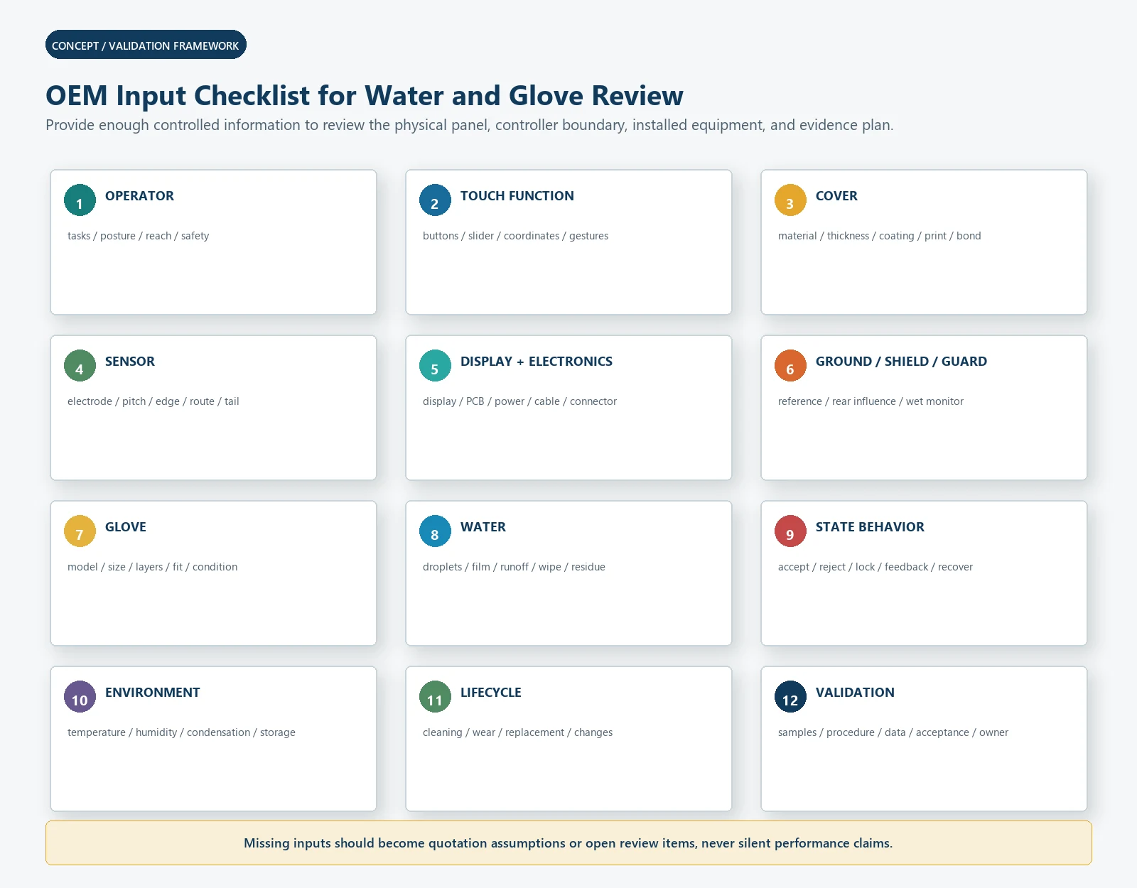
OEM Input Checklist
Provide:
- Equipment type, operator tasks, installation position, orientation, posture,
reach, and safety boundaries. - Touch architecture: buttons, slider, wheel, coordinate panel, multi-touch,
gesture, proximity, or combination. - Complete cover stack: material, thickness, coating, print, adhesive, gap,
curvature, mask, and surface condition. - Controlled sensor drawing: electrode, pitch, border, trace, tail, connector,
display registration, and inactive regions. - Display, PCB, power, cable, chassis, ground, shield, guard, bezel, gasket,
enclosure, and drainage details. - Controller, firmware, host, diagnostics, configuration, update, and ownership
boundary. - Every glove by manufacturer/model, material, size, layers, fit, condition,
wet/dry state, and operator posture. - Bare finger, wet finger, sleeve, palm, knuckle, stylus, tool, and invalid
object behavior. - Condensation, droplets, film, pooling, runoff, wipe, cleaning, residue, dry
recovery, and ingress requirements. - Accepted/rejected target, coordinate, response, release, false-event, missed-
event, feedback, lockout, recovery, and fault behavior. - Environment, electrical disturbance, storage, lifecycle, cleaning, wear,
replacement, spare, and obsolescence requirements. - Prototype stages, sample quantity, production volume, traceability, change
control, test ownership, and approval owners.
Frequently Asked Questions
Can capacitive touch work through thick gloves?
It can when the glove, cover, electrode, controller, ground, environment, and
acceptance criteria are designed together. Thick glove is not a controlled
specification. Test the exact glove model, size, layers, fit, wet/dry state,
posture, target, and invalid objects.
Does increasing sensitivity solve glove operation?
Not by itself. More sensitivity may improve a weak glove signal while reducing
margin against water, sleeves, palms, noise, edges, and assembly variation.
Review the complete signal margin and state behavior.
Can a capacitive panel work with wet fingers?
It can be designed to accept wet-finger input, reject it, or enter a restricted
wet mode. The required behavior must be defined and validated with controlled
water, targets, movement, enclosure, feedback, and recovery.
What is the difference between moisture tolerance and spill rejection?
Moisture tolerance tries to preserve valid touch operation under limited
moisture. Spill rejection detects a liquid condition and suppresses or restricts
normal input. They use different acceptance criteria and may require different
guard, controller, software, and UI behavior.
Does a guard ring make capacitive touch waterproof?
No. A guard or guard channel can help detect or manage liquid in selected
architectures. Waterproofing or an IP target depends on the complete enclosure,
gasket, seams, fasteners, tail, connector, assembly, test configuration, and
post-test function.
Should the system lock out during cleaning?
Often that is a useful option, but it is not automatic. Define how cleaning mode
starts, which controls remain available, how it is shown, how it exits, and what
happens after a wipe, spill, timeout, or power cycle.
Why does a panel pass on the bench and fail in the enclosure?
The installed display, power, cable, chassis, ground, shield, bezel, gasket,
metal, orientation, drainage, and host software can change the signal and state
behavior. Validate the complete installed stack.
What data should be saved during tuning?
Where the controller permits, save raw data, baseline, delta, noise, threshold,
hysteresis, detected state, guard/wet state, coordinates, rejected events,
response, release, recovery, firmware/configuration, and the exact hardware,
glove, water, and environment condition.
Send the Real Glove, Cover, and Wet-State Requirements
Submit the cover drawing, sensor concept, display and enclosure data, controlled
glove list, water-state table, controller plan, ground/shield/guard boundary, and
validation targets through the JASPER RFQ
form. The first review should expose
whether the project has enough signal and state margin before artwork, electrode
layout, bonding, and tooling are frozen.
Sources
- JASPER Electronics, “Custom Capacitive Touch Panels and Switches.”
https://www.jasperele.com/products/capacitive-touch-panels/ - JASPER Electronics, “Capacitive Touch Switch Guide.”
https://www.jasperele.com/resources/capacitive-touch-switch-guide/ - JASPER Electronics, “Membrane Switch Testing and Quality Control.”
https://www.jasperele.com/quality/testing/ - JASPER Electronics, “Membrane Switches for Home Appliances.”
https://www.jasperele.com/applications/home-appliances/ - JASPER Electronics, “Request a Quote.”
https://www.jasperele.com/request-a-quote/ - Microchip Technology, “Capacitive Touch Sensor Design Guide AN2934.”
https://onlinedocs.microchip.com/oxy/GUID-A8A0085D-58D1-4E41-A07D-B93BFDE11AFE-en-US-4/GUID-80CF1688-09E6-46D2-B2C6-44743EA74277.html - Microchip Technology, “AVR3002: Moisture Tolerant QTouch Design.”
https://ww1.microchip.com/downloads/aemDocuments/documents/OTH/ApplicationNotes/ApplicationNotes/doc42017.pdf - Texas Instruments, “CapTIvate Technology Guide: Design Guide.”
https://software-dl.ti.com/msp430/msp430_public_sw/mcu/msp430/CapTIvate_Design_Center/1_83_00_08/exports/docs/users_guide/html/CapTIvate_Technology_Guide_html/markdown/ch_design_guide.html - Texas Instruments, “TIDM-1021: Liquid Tolerant Capacitive Touch Keypad
Design.”
https://www.ti.com/tool/TIDM-1021 - International Organization for Standardization, “ISO 9241-210:2019,
Ergonomics of human-system interaction – Part 210: Human-centred design for
interactive systems.” https://www.iso.org/standard/77520.html - International Electrotechnical Commission, “IEC 60529:1989+AMD1:1999+AMD2:2013
CSV, Degrees of protection provided by enclosures (IP Code).”
https://webstore.iec.ch/en/publication/2452
Ready to Start Your Project?
Tell us about your membrane switch, keypad, or graphic overlay requirements. Our engineering team will review your specifications and provide a detailed quote.