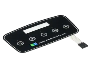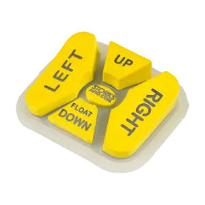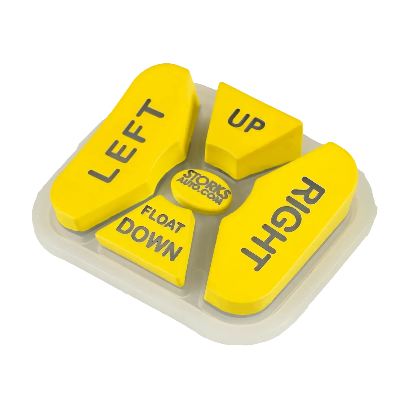
A silicone keypad and a tactile switch are not necessarily competing technologies. They sit at different levels of the control stack.
In a silicone-contact keypad assembly, the molded key usually provides the user surface, spring action, guidance, and return force, while a conductive pill or another contact method closes the circuit. In a discrete tactile-switch assembly, individual PCB-mounted switches provide the electrical switching event and much of the snap feel. The external actuator can still be plastic, metal, or silicone.
The real OEM decision is therefore not “rubber or switches.” It is which part owns the spring, switching, guidance, sealing, assembly tolerances, and service strategy. JASPER’s Silicone Rubber Keypad Design Guide uses this same finger-to-circuit approach.
- Define the Two Assemblies Being Compared
- Silicone-contact keypad assembly
- Discrete tactile-switch assembly
- Comparison Matrix
- Compare Force, Travel and Key Guidance
- Review Seals, Bezels and Mounting Space
- Compare Wiring and Assembly Work
- Illustrative Example: Same 12-Key Space
- Evaluate Serviceability and Total Project Scope
- How to Choose
- Discuss Your Interface Requirements
Define the Two Assemblies Being Compared
Silicone-contact keypad assembly
One molded keymat may contain many keys. Each key deforms through a molded web and may carry a carbon pill, conductive ink, metal contact, dome actuator, or other switching feature. The silicone can combine several jobs: visible button, spring, guide, contact carrier, sealing feature, legend surface, and light-control feature.
The circuit remains a separate element such as a rigid PCB, FPC, PET circuit, or membrane layer.
Discrete tactile-switch assembly
Here, an individual tactile switch component sits at each key position on the PCB. The external button transfers finger force into the switch plunger. That button can be a separate plastic cap or a non-conductive silicone key.
This hybrid point is important: a silicone key can actuate a tactile switch. JASPER’s conductive-rubber keypad page already lists a non-conductive actuator that presses a separate switch.
Comparison Matrix
| Comparison object | Silicone-contact keypad assembly | Discrete tactile-switch assembly | Customer should confirm |
|---|---|---|---|
| Tactile element | Molded web and key geometry usually create most of the force-displacement behavior | Switch mechanism creates the main snap; external actuator can add preload, friction and travel | Target force curve, travel, glove use, repeat rate |
| Electrical switching | Conductive pill, ink, metal contact, dome, or another contact closes the circuit | Switch package closes the circuit internally | Electrical load, contact requirement, firmware/debounce needs |
| User-facing button | Usually integrated into one molded keymat | Separate caps, molded buttons, or a silicone actuator mat | Shape, spacing, legends, texture, lighting |
| Key guidance | Web, side geometry, housing opening, ribs or carrier control motion | Keycap/housing must deliver force without excessive side load | Wobble, side load, hard stop, tolerances |
| PCB work | Contact pads, support and alignment are critical | Switch footprints, placement, soldering and actuator clearance are required | Existing PCB, area, keep-outs, assembly process |
| Sealing | One-piece silicone can simplify the front-side barrier, but enclosure sealing still needs system validation | Sealed switch variants exist, but button openings and enclosure joints remain separate paths | Exposure, cleaning method, test configuration |
| Assembly work | Locate keymat, circuit and enclosure; control compression and contact alignment | Place/solder switches, then align actuator and bezel system | Supplier boundary and assembly ownership |
| Service path | Key damage may mean replacing the complete keymat | A switch may be board-reworkable if access and service policy allow it | Field repair, module swap, depot repair |
| Validation | Force-displacement, contact closure, return, alignment, sealing | Switch specification plus actuator alignment, soldering, installed feel and sealing | Fixture, test speed, environment, sample stack |
Neither architecture is universally better. The decision becomes clearer only after the OEM assigns ownership for the key surface, spring, electrical contact, guide, seal, PCB support and final test.

Compare Force, Travel and Key Guidance
For a silicone-contact key, force and travel come from the complete installed geometry: key top, molded web, material, contact height, PCB support, enclosure preload and hard stop. A loose keymat can therefore feel different after installation.
A useful approval checks the press and release curve, electrical switch point, overtravel, bottoming and return behavior rather than relying on one force number.
Tactile switches also vary by model. Panasonic’s Light Touch Switch Design Guide treats push force and travel as application-selection variables. The switch datasheet, however, does not define the entire HMI feel. The external actuator can add free travel, preload, friction, compliance and bottoming.
Guidance matters especially when a cap or silicone key presses a discrete switch. Omron’s Tactile Switch Safety Precautions state that the plunger should operate in a straight vertical line and warn that off-center or angled operation can reduce switch life.
A hybrid silicone-over-tact-switch design should also avoid creating two unintended tactile events. If both the silicone web and switch have a strong snap, the installed curve can feel very different from either component alone. Validate the assembled key, not just the catalog switch.
Review Seals, Bezels and Mounting Space
A molded silicone keymat can cover multiple key locations with one continuous elastomer surface and may include a perimeter lip or compression feature. This can simplify the visible sealing path, but it does not by itself establish an enclosure rating. Fasteners, cable exits, displays, connectors and mating-part tolerances still belong to the tested system.
A sealed tactile switch protects the switch only within the manufacturer’s defined construction. The equipment may still admit contamination around the button, bezel, panel opening or enclosure joint. Keep two questions separate:
- Is the switch component suitable for the local exposure?
- Is the finished control interface sealed in the exact shipped assembly?
Space should also be compared as a full cross-section. A small tactile-switch footprint may still require switch height, plunger clearance, keycap, guide and hard stop. A silicone-contact keypad removes the discrete switch package but still needs key travel, circuit support and enclosure compression.
Compare Wiring and Assembly Work
At schematic level, both architectures may simply provide momentary inputs to a controller. Their manufacturing work is different.
A silicone-contact route commonly requires: mold and finish the keymat, define the underside contact, fabricate the circuit contact pattern, locate keypad to PCB, control support/compression, assemble the enclosure, and test installed feel plus electrical closure.
A discrete tactile-switch route commonly requires: select the controlled switch part number, place and solder each switch, inspect the populated board, install the external actuator system, control plunger alignment/preload/hard stop, assemble the bezel or seal, and test every input.
The silicone route can consolidate many keys into one molded part but shifts more design responsibility into custom geometry and tooling. The discrete route uses catalog switch components but adds one placed/soldered switch per key and may still need custom caps, bezel features or a silicone actuator layer.
Neither sequence proves lower cost. Tooling, switch BOM, PCBA work, housing complexity, test effort, expected volume and revision risk must be quoted to the same assembly boundary.
Illustrative Example: Same 12-Key Space
Illustrative example only — not a JASPER customer case, quotation, or measured test.
Assume an OEM must fit 12 momentary keys in the same 90 × 45 mm front-panel footprint, with the same general PCB outline and available enclosure depth. There is no backlighting in this example.
Option A: silicone-contact assembly. One molded 12-key mat sits over 12 PCB contact locations. Enclosure datums support and locate the stack. If one visible key is torn, service may require replacement of the whole keymat. If a PCB contact is damaged, replacing the rubber alone does not correct the electrical fault.
Option B: 12 tactile switches under external actuators. The PCB carries 12 individual switches plus a separate actuator system — either 12 caps or one non-conductive silicone mat. If one switch fails electrically, board-level replacement may be possible, but only when the product allows access and controlled rework. If the external actuator tears, the switch can remain electrically good while the actuator layer still requires replacement.
The example shows why the same front-panel space can create different BOM structure, tooling ownership, assembly stations and spare-parts strategy.
Evaluate Serviceability and Total Project Scope
Serviceability should be defined before architecture selection. Decide whether the product will be repaired by replacing the whole HMI, swapping the PCB, changing a keypad/actuator layer, or reworking individual components.
A tactile switch is not automatically “easy to repair.” An SMT device under a sealed panel may require full disassembly and solder rework. A silicone keypad is not automatically “non-serviceable”; a retained keymat can be a replaceable part if the enclosure is designed for it.
Procurement should compare the total project scope:
- keypad or actuator tooling ownership;
- approved switch part numbers and second-source policy;
- PCB assembly responsibility;
- bezel, gasket and housing tooling;
- installed key-force acceptance;
- sealing validation;
- electrical test responsibility;
- spare-parts and repair method;
- production quantity and change risk.
If purchasing wants one integrated module rather than separately coordinated rubber, circuit and mechanical parts, review silicone keypad assemblies.
How to Choose
A silicone-contact keypad is worth evaluating when the product needs a multi-key molded surface, integrated finger location, shared sealing geometry, controlled legends/backlighting, and a custom interface expected to remain stable through production.
A discrete tactile-switch architecture is worth evaluating when the PCB already uses defined switch locations, a catalog switch’s mechanical/electrical characteristics are useful, or the switching element should remain separate from the cosmetic actuator.
A silicone actuator over tactile switches is a valid third route when the OEM wants a molded or cleanable user surface but prefers discrete PCB switches.
Do not choose from the front view alone. Compare a section through one key and assign ownership for spring, switch, guide, seal, hard stop, PCB support, assembly and validation.
FAQ
Are silicone keypads and tactile switches mutually exclusive?
No. A silicone key can close PCB contacts directly, actuate a metal dome, or press a separate tactile/mechanical switch.
Which option gives better tactile feel?
Neither has a universal advantage. The final feel depends on the complete installed force path, not only the silicone material or the switch datasheet.
Which option is easier to seal?
A one-piece silicone keymat can simplify the front-side sealing geometry. Sealed tactile switches can protect the component itself. The finished enclosure still needs system-level validation.
Are tactile switches easier to replace?
Sometimes. It depends on PCB access, solder-rework policy and the product’s intended service boundary.
Which architecture is cheaper?
There is no safe universal answer. Compare mold/tooling cost, switch BOM, PCB assembly, actuator/bezel parts, validation, expected volume and revision risk.
What should we send for an architecture review?
Send the front-panel layout, PCB status, key count and spacing, available depth, enclosure section, target feel, environment, lighting needs, quantity, validation requirements and service strategy. Unknown items can be marked TBD.
Discuss Your Interface Requirements
To compare a silicone-contact keypad, discrete tactile switches, or a hybrid silicone-over-switch architecture, submit:
- 2D drawing, STEP file, enclosure section, or sample photo;
- key count, size, spacing and available depth;
- PCB/Gerber/schematic/contact layout or existing switch part numbers;
- target force, travel, feel or approved reference sample;
- water, dust, cleaner, oil, UV, glove and temperature requirements;
- legends, coatings, lighting and indicators;
- prototype quantity and expected annual volume;
- intended service boundary;
- validation or compliance requirements;
- unresolved items marked TBD.
Ready to Start Your Project?
Tell us about your membrane switch, keypad, or graphic overlay requirements. Our engineering team will review your specifications and provide a detailed quote.