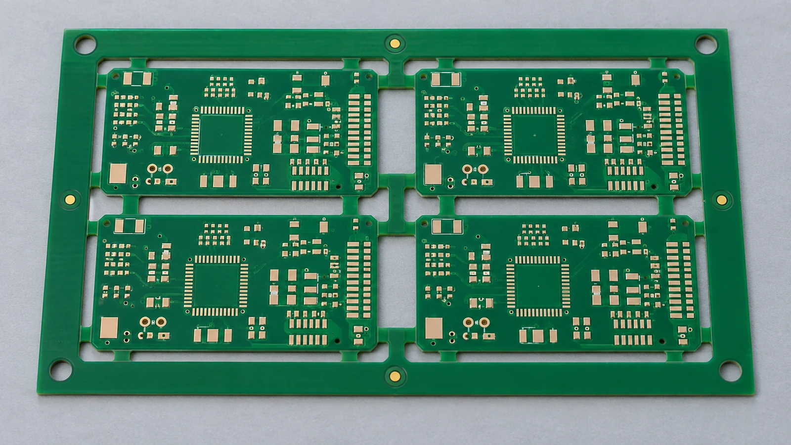
PCB depanelization component stress is the mechanical loading transferred into components, solder joints and nearby laminate when an assembled board is separated from its panel. Control it by reviewing the separation path, component position and orientation, and the support available throughout the cut. No single edge clearance or board-strain limit establishes safety for every assembly. Use the selected component requirements and the actual separation process to set acceptance criteria, then validate the highest-risk locations before production release.
- Understand the Load Path Before Choosing a Separation Process
- Map Stress-Sensitive Components Near the Separation Path
- Compare Routing, V-Scoring and Other Separation Methods
- Review Tabs, Scores and Tool Access in the Panel Design
- Match the separation feature to the equipment
- Review the last connection, not just the first cut
- Support the Board During Separation and Handling
- Plan Strain Measurement Where Risk Justifies It
- Establish the applicable specification before testing
- Measure the event that the requirement describes
- Build a repeatable project measurement plan
- Apply the Review to Five Assembly Scenarios
- Compact sensor board with an MLCC beside a tab
- Long control board separated along V-scores
- Processor board with an FCBGA near a removable rail
- Interface board with an overhanging connector
- Thin board moving from routing to laser separation
- Close Depanelization Risks Before Production Release
- Prepare the Separation Review With JASPER
Understand the Load Path Before Choosing a Separation Process
Depanelization risk follows the load path from the separator, through the supported board, into the component attachment. A clean board edge does not prove that this load path was harmless. Review what bends, what remains constrained, and what becomes unsupported as each connection to the panel disappears.
For a ceramic capacitor, board deformation moves the copper lands and loads the soldered terminations. Excessive deformation can crack the ceramic. Other assemblies can experience solder-joint damage, pad lifting or pad cratering, in which the laminate beneath a pad fractures. These are different failure mechanisms, not interchangeable names for a visibly broken solder joint.
Stress and strain are also different. Stress describes internal mechanical loading per unit area; strain describes deformation relative to original length. A board-mounted strain gauge measures local board strain, not the stress inside a ceramic body or every solder connection. Relating that measurement to damage requires the applicable component and assembly conditions.
For review purposes, follow the complete sequence: load the panel, locate it, clamp it, separate the boards, release the fixture and transfer each board. This transient loading review is distinct from assessing overall board warpage.
Map Stress-Sensitive Components Near the Separation Path
Stress-sensitive components should be mapped against the actual cut, score or tab-removal path, not only against the finished board outline. Start with multilayer ceramic capacitors, then include packages with supplier handling restrictions and components whose weight or protrusion changes how the board is supported.
Record each component’s reference designator, manufacturer part number, package, mounting side and orientation. Dimension the relevant body, termination or land relative to the separation feature, stating which feature each dimension uses. A body-to-edge distance and a solder-land-to-tab distance answer different questions; do not mix them in a clearance review.
Orientation deserves its own decision. Parallel alignment to a separation line is one layout measure to evaluate. For a two-terminal MLCC, identify the terminal-to-terminal axis explicitly. Treat parallel alignment as a starting point, not proof of safety: an offset tab, corner, slot or changed support arrangement can alter the local bending direction.
Use this project review matrix to connect each exposure to an action and an observable result.
| Risk Factor | Affected Component or Area | Separation Interaction | Mitigation Option | Verification Evidence |
|---|---|---|---|---|
| Edge-adjacent ceramic parts | MLCC bodies, terminations and lands | Local bending loads the soldered ceramic | Relocate or reorient the part; review an electrically suitable flex-resistant alternative | Approved component guidance, dimensioned layout and local strain results where required |
| Breakaway-tab location | Parts beside a tab or narrow board neck | Tab removal concentrates loading near its attachment | Move the tab, machine it away or provide local support | Released tab drawing, cut sequence and instrumented trial where justified |
| V-score path | Components alongside the scored line | Blade loading and residual web affect separation | Match score geometry to the separator and qualify blade settings | Fabrication measurements, controlled recipe and process trial |
| Unsupported board span | Flexible regions between supports | Cutting or clamping deflects the span | Add component-safe support near the active load | Fixture contact map and loading-through-unloading observation |
| Connector leverage | Connector joints and adjacent components | Gripping or cable forces bend the board | Grip approved board areas; restrain cables separately | Work instruction and transfer or insertion trial |
| Post-separation handling | Freed board, fragile corners and edge components | Lift-out, stacking or edge finishing adds loading | Define supported removal and protective tray placement | Handling observation, tray review and relevant strain capture |
Compare Routing, V-Scoring and Other Separation Methods
Separation methods should be compared by how they load the populated board and by the evidence needed to qualify them. V-scoring is a panel feature, not a complete description of the separation operation. Breaking a scored board by hand is not equivalent to separating it with a controlled blade system.
The following methods are practical alternatives for this review, not a universal ranking from safest to least safe. Equipment manufacturers distinguish routing, sawing, laser cutting, scored-board separation and local off-cut removal; their suitability depends on the panel and process.
| Separation Method | Interaction With the Assembly | Main Review Priority | Appropriate Verification |
|---|---|---|---|
| Routing | A rotating cutter removes tabs or board material | Cutter access, retention of the freed board, cutting parameters and debris extraction | Trial with production tooling, edge inspection and local strain measurement where required |
| V-score blade separation | Blades separate the remaining web along a groove | Score consistency, blade alignment, pass sequence and component clearance | Actual scored panels, controlled blade recipe and repeatable support |
| Manual breaking | Operator-applied bending or twisting fractures tabs or scores | Grip position, motion variability and load transmitted to sensitive parts | Documented justification and representative operator trials; replace the method when control is inadequate |
| Punching or tab cutting | A punch or local cutting tool removes connections | Matched support, tool clearance and complete tab removal | Tooling trial, retained-board inspection and strain capture where justified |
| Sawing | A saw removes material along a cut line | Blade clearance, clamping, straight-line access and cleanliness | Production-representative cutting and release trial |
| Laser separation | Non-contact energy removes material along the path | Material compatibility, thermal effects, extraction and subsequent handling | Cut-edge and cleanliness assessment plus a fixture and unloading review |
Routing can avoid deliberately bending a tab until it fractures, but it does not eliminate fixture or handling loads. Retain both the panel frame and individual boards while milling away the connecting tabs. That distinction matters at the last tab, when the board otherwise loses its connection to the frame.
For scored panels, cab’s MAESTRO 4S documentation describes reduced loading through staged blade traverses in a particular setup. Use that as evidence that the blade process matters, not as permission to copy its sample geometry or settings onto another assembly.
Laser separation removes direct cutting-tool contact, but it still requires process qualification. Layer-by-layer thermal ablation and fume extraction are part of the laser-process review. Review the material response and handling sequence rather than equating non-contact cutting with zero risk throughout the manufacturing station.
Review Tabs, Scores and Tool Access in the Panel Design
Tabs, scores and tool access must be reviewed together because changing a separation feature changes both local loading and the restraint available to the board. Approve a separation drawing that shows the populated assembly, fixture interfaces and sequence, not merely the bare-board outline.
Match the separation feature to the equipment
For a routed assembly, identify which connections are machined away and which, if any, remain for another operation. Confirm access for the cutter and its surrounding hardware on both sides of the panel. A clear tool centerline is insufficient when a connector body, underside component or fixture contact occupies the surrounding space.
For a scored assembly, define the groove location and residual web in the fabrication data, then reconcile them with the separator’s requirements. The remaining material is part of the mechanical system. Inspect representative delivered panels rather than assuming that the drawing alone establishes the production condition.
Review the last connection, not just the first cut
Mark the order of tab removal and identify what supports each board after every step. Do not leave a sensitive corner attached to a single connection merely because that sequence shortens machine travel. Consider whether the frame can move into a freed board and whether the operator must flex the assembly to remove it.
Treat tab-stub trimming, sanding or a second separation operation as part of the same review. Removing the main panel successfully does not qualify an uncontrolled finishing operation afterward. Control bending and twisting after capacitors are mounted, including during these finishing steps.
Support the Board During Separation and Handling
Board support should react the separation load without pressing on components or forcing the assembly into a distorted shape. Support only at approved contact areas, and preserve retention after the final cut. Purpose-built routing fixtures use locating and support features to control board movement during separation.
Review the fixture against the fully populated underside. Identify support contacts, locating pins, clamps, vacuum regions and clearance pockets. Check that a support does not land on a solder joint, ceramic body or protruding lead. A fixture that fits a bare PCB can interfere with its assembled version.
Observe loading and clamp closure before evaluating cutting. An operator should not need to press the board flat against a mismatched nest. During unloading, release restraints in a defined order and lift from approved areas rather than pulling on an overhanging connector. Include attached cables and any temporary test hardware in this review.
Do not replace the production population with a bare board when the missing parts would change stiffness, mass or fixture access. A bare-board trial can establish tool clearance, but it cannot automatically represent the mechanical response of the assembly.
Keep the first downstream operation visible. Place separated boards in trays that avoid loading sensitive areas, and include connector insertion when it occurs immediately after separation. For the FCBGA/ENIG assembly example, edge-guide snap-off and manual connector insertion are mechanically severe operations that warrant assessment.
Plan Strain Measurement Where Risk Justifies It
Strain measurement is useful when a layout or process decision cannot be justified confidently from applicable component guidance and established production evidence. Prioritize edge-adjacent ceramics, constrained package locations, changing support conditions, manual operations and process changes associated with unexplained failures.
Establish the applicable specification before testing
IPC/JEDEC-9704A, Printed Circuit Assembly Strain Gage Test Guideline, provides a methodology for measuring assembly strain during manufacturing, testing and handling. Its publicly available scope identifies strain and strain rate as relevant quantities and recognizes limits established by customers, component suppliers or internal practices. It is not a universal component acceptance limit.
Obtain the selected component’s applicable handling or board-strain requirement and identify the board construction, attachment configuration, gauge location and strain metric to which it applies. A board-bend displacement from a component qualification fixture is not automatically a permissible displacement for an assembled production panel.
Where a transferable limit is unavailable, agree a qualification method with the component supplier and product reliability owner. Define the evidence needed to release the process; do not manufacture a microstrain threshold from another supplier’s equipment page or an unrelated product.
Measure the event that the requirement describes
Local strain is expressed as ε = ΔL/L; one microstrain, written µε, equals 10^-6 strain. Record strain rate in compatible units such as µε/s. Preserve tensile and compressive signs. Compare the specified directional or principal strain metric with its matching criterion; a strain-rate result cannot be assessed against a strain-only limit.
Select gauge positions around the components and load paths being evaluated. A uniaxial gauge measures strain along its sensing axis. A rosette provides multiple directional measurements from which principal strains can be calculated. Choose the arrangement required by the qualification plan, rather than using whichever location is easiest to instrument.
Document the board side, gauge orientation and position relative to the package. Record the gauge factor, bridge configuration, zero reference and temperature compensation; temperature-dependent resistance can otherwise introduce measurement error. Secure leads without pulling on the board or obstructing the tool. Retain production components where practical, and assess the effect of any removal or substitution.
Build a repeatable project measurement plan
Use the following plan to make the experiment reproducible. These records connect the result to the tested process rather than to a machine name alone.
| Measurement Record | Required Content | Decision It Supports |
|---|---|---|
| Assembly identity | PCB revision, stack-up, thickness, population and relevant component part numbers | Whether the tested hardware represents production |
| Sensor arrangement | Gauge type, location, orientation, attachment and lead routing | Whether measurements correspond to the component-specific requirement |
| Acquisition setup | Calibration check, sampling, bandwidth, filtering, trigger and recording window | Whether short-duration events can be captured and compared |
| Process conditions | Fixture revision, clamp sequence, tool condition, recipe, panel position and operator where relevant | Whether variation and the final release condition were represented |
| Results and disposition | Time histories, specified strain metrics, applicable limits, inspection findings and corrective actions | Whether to approve, modify or repeat qualification |
Record from panel loading through tray placement, and label the individual events. Choose acquisition settings that resolve the event duration; demonstrate that filtering or undersampling has not hidden a relevant peak. Include repeated trials and representative panel positions, with sample coverage agreed from product risk rather than a universal sample count.
A lower measured peak supports a process comparison only when the hardware, sensor arrangement and analysis are comparable. It does not establish freedom from every failure mode. Pair measurements with inspection or component-level analysis appropriate to the suspected damage and with the product’s functional checks.
Apply the Review to Five Assembly Scenarios
These five assembly scenarios show how component exposure changes the separation decision. They are engineering examples, not production results. In each case, qualify the combination of layout, method, support and handling rather than approving a technology label alone.
Compact sensor board with an MLCC beside a tab
Review whether the tab can move before accepting the capacitor location. Compare the terminal axis with the expected local bending direction and check support beneath the affected region. When layout changes are constrained, evaluate controlled tab removal and determine whether local strain measurement is needed. A flex-resistant capacitor option still requires electrical and package approval.
Long control board separated along V-scores
Focus on how the board is supported before, during and after blade travel. Review groove consistency and the permitted blade sequence together. Include end and interior panel positions in the trial when their restraint differs. Do not infer acceptability from a single easily handled sample or from the absence of an obvious edge defect.
Processor board with an FCBGA near a removable rail
Use the exact package guidance to identify relevant strain metrics and measurement locations. Assess rail removal as part of the assembled-board process, including clamp closure and fixture release. Investigate snap-off loading in the FCBGA handling example without extending its package- and finish-specific conclusions to unrelated assemblies.
Interface board with an overhanging connector
Check both cutting clearance and how the connector affects unloading. The easiest handhold may also apply the largest bending moment to its attachment region. Define a board-supported grip and separate cable restraint. Keep this review focused on separation and immediate transfer; the wider mechanical support design belongs in the assembly support review.
Thin board moving from routing to laser separation
Reassess rather than automatically carrying over the routing approval. Direct cutter forces change, but fixture loading and board pickup remain. Verify the laser process against the material stack and cleanliness needs, then confirm that the newly freed board can be removed without bending. Preserve comparable measurement locations where a before-and-after strain study is required.
Close Depanelization Risks Before Production Release
Depanelization risks are closed when each significant component exposure has an approved control and evidence appropriate to the failure mechanism. Neither a clean cut nor a functional pass alone establishes that mechanically sensitive parts are undamaged. Some capacitor cracks are difficult to detect externally and can lead to degraded insulation resistance.
Use a defined release sequence: approve the risk map, freeze the separation drawing, qualify the fixture and recipe, review the evidence, then issue the work instruction. Assign the PCB designer responsibility for layout changes, manufacturing engineering for the separation process, and quality or reliability engineering for acceptance evidence. The product owner resolves any remaining risk disposition.
Retain the approved tool and fixture revisions, support map, component restrictions, measurement results where required, and operator handling instructions. Include the final tab, rail removal and downstream transfer in the released operation.
When damage is suspected, preserve samples and establish when the defect first appeared. Compare evidence before and after separation and distinguish ceramic cracking, joint fracture and laminate damage. For a suspected internal MLCC crack, appropriately located cross-section analysis can reveal damage hidden from external inspection. Discovery after separation alone does not establish the cause.
Define requalification triggers around changes that alter the load path: component substitution, board construction, tab or score geometry, fixture contacts, cut sequence, tool settings and handling. A successful corrective trial closes only the conditions it actually tested.
Frequently Asked Questions
The following answers address common PCB depanelization component stress decisions. Apply them together with the selected component documentation and the qualified process, especially when moving from prototypes to production or transferring an assembly between manufacturing lines.
Can a board pass functional test after a component is mechanically damaged?
Yes. A mechanically damaged component can remain electrically functional under the conditions of an immediate test. A ceramic crack may later impair insulation resistance or become electrically significant under different conditions. Functional testing is useful, but it does not replace prevention, process qualification or damage analysis selected for the suspected failure mechanism.
How close can a ceramic capacitor be to a depanelization edge?
There is no universal safe distance for every ceramic capacitor and separation process. Determine clearance from the selected component guidance, its orientation, the tab or score location, board construction and support arrangement. Define the dimension reference explicitly, then validate the proposed layout and production method where mechanical risk remains significant.
Does routed depanelization eliminate all board stress?
No. Routing can remove connecting material without deliberately snapping the board, but clamping, cutter interaction, an unsupported final tab and unloading can still load the assembly. Qualify the routing process with its fixture, cut sequence, tool condition and handling steps rather than treating the machine type as proof of safety.
When is strain measurement useful for a PCBA separation process?
Strain measurement is useful when sensitive components, restricted clearances, variable handling or a changed separation process create uncertainty about mechanical loading. Establish the applicable acceptance criterion first, then instrument representative assemblies and capture the complete operation. Use the results to compare controls and qualify the defined process, not to claim universal component immunity.
Should component orientation be reviewed near a breakaway tab?
Yes. Review the component’s terminal axis against the expected local bending direction, not just the finished board edge. Parallel placement relative to a separation line is a useful starting point for many two-terminal ceramic capacitors, but offset tabs and changing restraints can alter local deformation and require a different solution.
Can a flexible-termination capacitor replace a separation-process change?
Not automatically. A flexible-termination capacitor can be a mitigation option, but it must meet the circuit’s electrical and reliability requirements and the selected part’s mechanical conditions. Review the replacement together with board support and separation controls. A component substitution does not qualify an otherwise uncontrolled bending or twisting operation.
What should a depanelization strain report contain?
A useful report identifies the assembly and fixture revisions, sensor positions and orientations, acquisition settings, operating conditions and complete event sequence. It presents the required strain metrics against the applicable acceptance criteria, preserves time-history evidence, and records corrective actions. The report should make clear which production conditions were represented by the qualification.
Which changes require a new depanelization risk review?
Review changes to component type or orientation, PCB construction, tabs, scores, support contacts, cutting sequence, tooling and handling. Repeat measurement or qualification when the change could invalidate existing evidence. The decision should follow the changed load path and product risk, rather than assuming that an unchanged board outline preserves approval.
Prepare the Separation Review With JASPER
Prepare the panel drawing, PCB stack-up, BOM, component placement data, assembly drawings and component-specific handling requirements for the separation review. Include any existing fixture design, strain report and photographs of suspected damage. Identify which parts or layout features cannot move so the discussion can focus on viable controls.
Discuss the proposed separation method and validation responsibilities with JASPER through its PCB assembly services. Agree the layout, support, handling and release evidence before authorizing the production process—not after a damaged batch has passed through it.
Ready to Start Your Project?
Tell us about your membrane switch, keypad, or graphic overlay requirements. Our engineering team will review your specifications and provide a detailed quote.