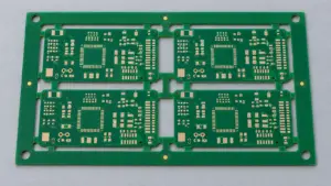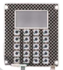
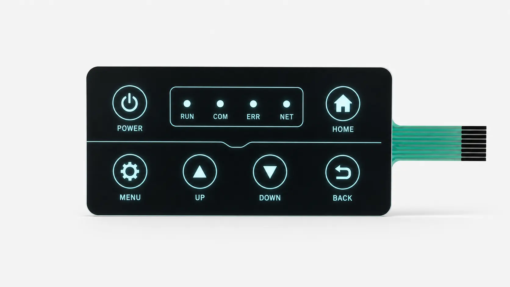
Poorly engineered backlighting can make a $10,000 piece of medical or industrial hardware look like a cheap toy. Across custom HMI builds, two optical defects account for almost every prototype rejection on illuminated panels: (1) harsh, blinding LED hotspots directly over the diode emitter with dark drop-offs at the edges of the button legend, and (2) light bleeding (optical crosstalk) into adjacent unlit status indicators or glowing through the dark background bezel.
Because a standard membrane switch stack is only 0.80 mm to 1.30 mm thick, there is virtually zero vertical air space for a top-firing SMD LED (120° viewing cone) to diffuse naturally before hitting the graphic overlay. Here is how JASPER engineers uniform, zero-bleed backlit membrane switches and dead-front graphic overlays for nighttime, darkroom, and surgical environments.
1. Comparing the Three Backlighting Architectures: LGF vs. Direct SMD LED vs. EL
Choosing the right illumination technology depends on whether you are lighting individual point status indicators or full-panel button legends and perimeter halos:
|
Optical & Electrical Parameter |
1. Optical Light Guide Film (LGF + Side-Firing LEDs) |
2. Direct Embedded Top-Firing SMD LEDs (0603 / 0805) |
3. Electroluminescent (EL) Phosphor Lamp Layer |
|
Illumination Uniformity |
Exceptional ( |
Point Source Only ( |
100% Uniform Surface Glow |
|
Operating Voltage & Driver |
Low-Voltage DC ( |
Low-Voltage DC ( |
Requires High-Voltage AC Inverter ( |
|
Operational Half-Life ( |
|
|
|
|
Tactile Dome Compatibility |
100% Compatible |
Separate From Dome Center |
Compatible (sits beneath or above the dome layer). |
|
Best Use Case |
Full-keypad legend backlighting, multi-zone color-changing status bars, medical/marine night panels. |
Discrete status indicators (POWER, FAULT, RUN) next to buttons. |
Legacy military/aviation replacements where an AC EL inverter already exists. |
2. How to Eliminate Light Bleed (Optical Crosstalk) Between Adjacent Icons
When you place a red FAULT indicator only 4.0 mm away from a green READY indicator, light launched from the red SMD LED travels sideways through the clear polyester overlay substrate and translucent acrylic adhesive via Total Internal Reflection (TIR)—causing the unlit READY icon to glow pink! At JASPER, we eliminate optical crosstalk through a four-part optical barrier stack:
- Double-Pass Opaque Black + Metallic Silver Blockout Ink (
OD > 3.5): On the rear of the graphic overlay, we screen-print a high-density metallic silver light-reflecting pass followed by two passes of opaque carbon-black light-blocking ink everywhere outside the illuminated icon vectors. 0.20 mmOptical Choke / Bleed Overlap: We overlap the opaque black blockout ink 0.20 mm inside the translucent colored icon border so registration tolerances (±0.15 mm) never leave a raw clear slit around the icon perimeter.- Black Light-Dam Spacer Cavities (Black PET / Black Foam Baffles): Instead of using clear double-sided adhesive spacers around LEDs, we die-cut isolated opaque black polyester or black closed-cell poron foam light dams around each individual LED chamber so stray photons cannot travel laterally between indicators.
- White Diffuser Ink Over LED Emitters: For direct top-firing SMD LEDs, we print two passes of translucent titanium-dioxide (TiO2) optical diffuser ink (40%–55% transmission) over the window underside to scatter the sharp diode die image into a soft, even glow.
3. Engineering ‘Dead-Front’ (Secret-Until-Lit) Warning Indicators
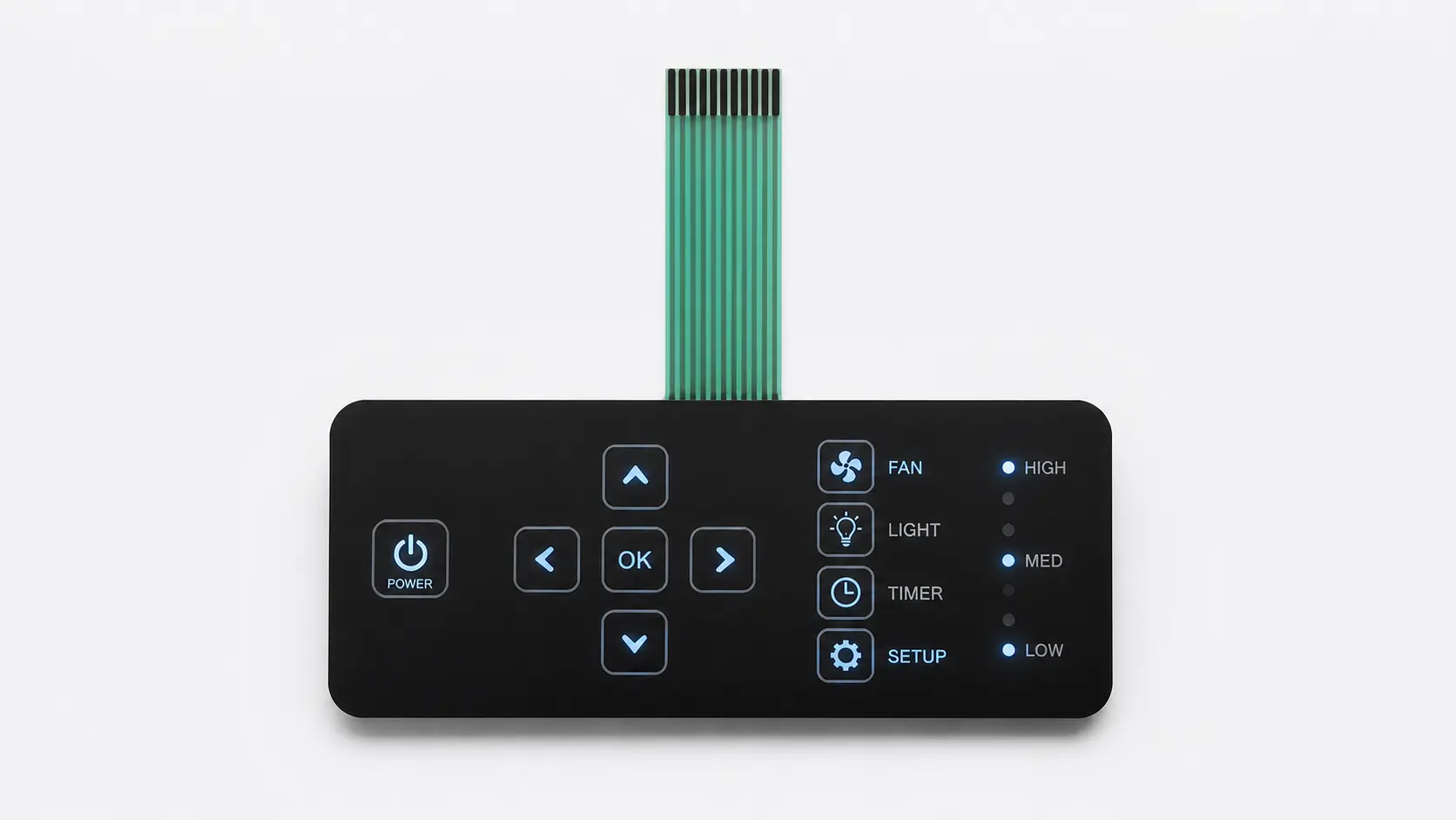
Modern medical monitors, automotive dashboards, and industrial HMIs increasingly use Dead-Front graphics—status icons (LOW BATTERY, OCCLUSION, HIGH TEMP) that appear completely matte black and invisible when powered off, appearing sharply in red, amber, green, or white only when the rear LED turns on.
Achieving a true dead-front effect requires balancing optical transmission between 10% and 18%. If the smoked window ink is too transparent (>25%), the white icon legend remains visible as a ghost outline under room lighting; if it is too dense (<8%), the LED looks dim in daylight. We calibrate dead-front windows by printing a translucent white + color filter legend on the subsurface, masked behind a precisely formulated neutral-density smoked velvet window ink matched to your surrounding black Pantone bezel.
|
Pre-RFQ DFM Checklist: 4 Optical Design Rules for Backlit Membrane Switches • [ ] Choose LGF Over EL Lamps for All New Designs: Optical Light Guide Film (LGF) gives you 10× longer life (50,000 hours), zero high-voltage AC inverter EMI noise, and effortless multi-zone color separation (e.g., white keys + red emergency stop halo). • [ ] Keep Top-Firing SMD LEDs at Least 3.5 mm Away From Metal Dome Edges: Pressing a metal dome next to an unisolated SMD LED flexes the overlay downward; a 3.5 mm clearance prevents the operator’s finger from feeling the rigid 0.6 mm LED body. • [ ] Maintain >= 3.0 mm Opaque Wall Width Between Adjacent Lit Windows: Give our die-cut black light-dam layer at least 3.0 mm of solid bridge width between a red and green indicator to guarantee zero color bleed. • [ ] Specify PWM Dimming Range for Night-Vision Panels: For marine bridge, cockpit, or ICU bedside monitors, drive LGF side-LEDs via a 1 kHz+ PWM channel so operators can dim backlighting down to 2% duty cycle without flicker. |
Frequently Asked Questions (FAQ)
Q1: Can a single Light Guide Film (LGF) illuminate different buttons in different colors?
Yes! We laser-cut optical isolation trenches (air gaps filled with opaque black adhesive baffles) inside the LGF sheet to divide a single panel into independent optical zones—allowing your main numeric keys to glow cool white while the START key glows green and the STOP key glows red, or even switch colors dynamically using bi-color/RGB side-firing LEDs.
Q2: Should current-limiting resistors for embedded LEDs sit on the membrane switch or on our main PCB?
Putting the current-limiting resistors on your main host PCB is always preferred: it reduces component bumps inside the membrane laminate, eliminates thermal dissipation inside the thin film, and lowers your unit switch cost. However, if pin count on the ZIF tail is strictly limited, we can embed 0603 SMD resistors directly on the switch circuit layer.
Q3: When should I use a Backlit Silicone Keypad instead of a Backlit Membrane Switch?
Choose our Backlit Membrane Switches when you want a sleek, thin (<1.2 mm), wipe-clean front surface. Choose our laser-etched Backlit Silicone Rubber Keypads when operators need deep 2.0–3.0 mm 3D sculpted keys that can be located by touch in pitch darkness.
See Your Backlit & Dead-Front Icons Come to Life
Want to eliminate hotspots and light bleed on your next illuminated HMI? Review our Backlit Membrane Switches page or send your artwork to our optical engineering team via Request a Quote.
Ready to Start Your Project?
Tell us about your membrane switch, keypad, or graphic overlay requirements. Our engineering team will review your specifications and provide a detailed quote.