When designing the electrical schematic for custom membrane keypads, hardware engineers must choose between two fundamental routing topologies: Direct Common-Bus Wiring (N + 1 pins) and Row-Column Matrix Scanning (M × N pins). While a 4 × 4 matrix reduces a 16-button keypad from 17 tail pins down to just 8 GPIO pins, an unisolated matrix introduces a dangerous electrical phenomenon known as Matrix Ghosting (Phantom Key Actuation) whenever an operator holds down three keys simultaneously.
In consumer microwave keypads where users only tap one digit at a time, an unisolated matrix works fine. In industrial CNC pendants, crane controllers, medical infusion pumps, or laboratory instruments—where operators routinely hold SHIFT + JOG UP + FAST or press two safety interlock keys while adjusting a third parameter—a phantom fourth key press can trigger unintended machine motion. Here is how our electrical design team engineers ghost-free membrane switch circuits.
1. The Physics of a 3-Corner Current Sneak Path (Why Ghosting Happens)
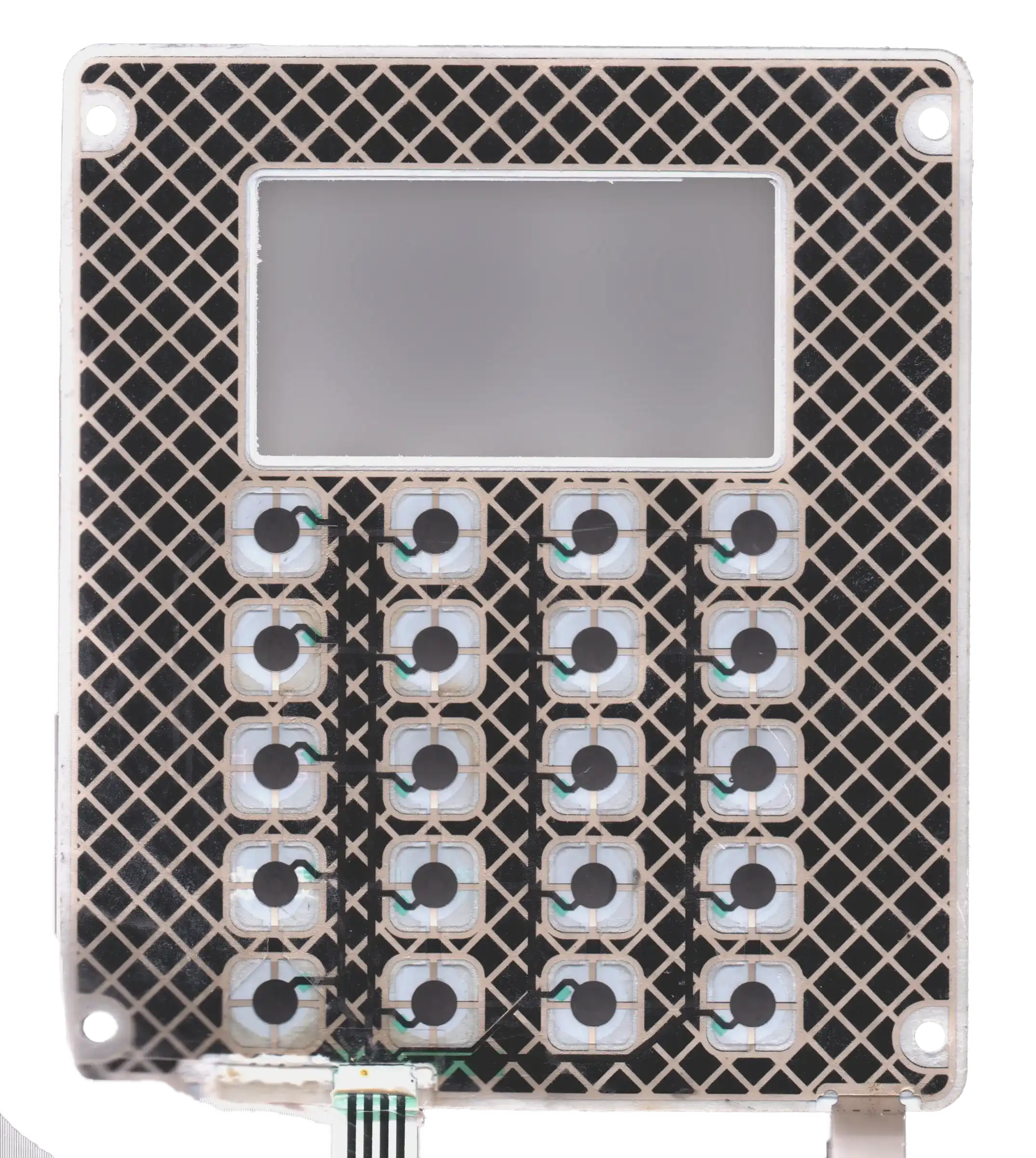
In a standard M × N membrane switch matrix, the upper circuit layer carries horizontal Row traces (R1, R2...Rm) and the lower circuit layer carries vertical Column traces (C1, C2...Cn), separated by a die-cut polyester spacer (0.125–0.175 mm). Your microcontroller scans the keypad by driving one column low (0 V) at a time while reading the state of all row pins pulled high (3.3 V or 5.0 V) through internal or external pull-up resistors.
Suppose an operator simultaneously presses three buttons that form three corners of a rectangle on the matrix grid: Key 1 (R1, C1), Key 2 (R1, C2), and Key 3 (R2, C1). When the MCU pulls Column 2 (C2) low to inspect Row 2 (R2), current flows out of R2, passes through closed Key 3 into C1, travels up C1 through closed Key 1 into R1, and finally exits through closed Key 2 into C2. Because R2 is pulled low through this three-switch sneak path, the microcontroller falsely concludes that the fourth corner—Key 4 (R2, C2)—is also pressed!
- Software Alone Cannot Eliminate True 3-Key Ghosting: While firmware can detect that 3 corners of a rectangle are active and ignore the 4th corner (2-Key Rollover / Phantom Lockout), blocking the 3rd key press is unacceptable when your user interface intentionally requires multi-key chording.
- Silver Ink Loop Resistance Does Not Provide Sufficient Isolation: Because screen-printed silver ink traces typically exhibit 0.5 Ω to 2.0 Ω per centimeter (for a total closed-loop resistance of 15 Ω to 80 Ω), the voltage drop across three series switches in a sneak path (<0.05 V with a 10 kΩ pull-up) still pulls the MCU input well below its logic-low threshold (V_IL <= 0.8 V).
2. Comparing the Three Membrane Keypad Wiring Topologies
When selecting among membrane switch types, use the engineering comparison table below to match your key count, simultaneous key-press requirements, and tail width:
|
Circuit Parameter |
1. Common-Bus Wiring (N + 1 Direct Pins) |
2. Standard Unisolated Matrix (M × N Pins) |
3. Diode-Isolated Matrix (M × N + SMD Diodes) |
|
Pin Count Example (16 Keys) |
17 Pins (16 independent switch lines + 1 shared GND/Common bus) |
8 Pins (4 Rows × 4 Columns scanning grid) |
8 Pins (4 Rows × 4 Columns with 16 series SMD diodes) |
|
Multi-Key Chording / Rollover |
100% N-Key Rollover ( |
1-Key to 2-Key Safe Only |
100% N-Key Rollover ( |
|
Circuit Substrate & Thickness |
Single-sided 0.125 mm PET silver/carbon circuit (simplest & lowest cost). |
Two-layer PET silver circuit with dielectric crossover bridges (0.025 mm). |
Polyimide FPC circuit or heavy PET with conductive silver-epoxy bonded SOD-323 diodes. |
|
MCU Firmware Complexity |
Zero scanning loop required; direct GPIO interrupt or shift-register read (74HC165). |
Requires periodic row/column timer polling (5–10 ms) + phantom key filtering. |
Standard row/column polling with full simultaneous chord recognition. |
|
Recommended Application |
Keypads with |
Numeric entry pads (0–9, *, #) where only 1 key is pressed at a time. |
Complex 16–64 key industrial controllers, synthesizer pads, and CNC pendants. |
3. How We Embed SMD Blocking Diodes Inside a Flat Membrane Switch
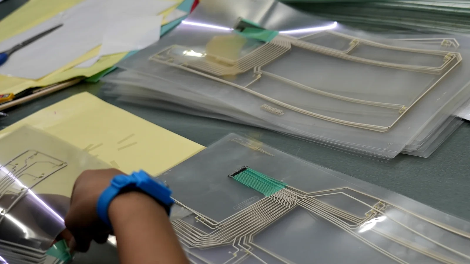
When your keypad has 20+ keys and requires multi-key chording, adding a series switching diode (1N4148WS in SOD-323 or ultra-thin SOD-523 / 0603 package, body height 0.60–0.85 mm) in series with every dome prevents reverse current flow through Key 1, breaking the sneak path completely. To keep the front graphic overlay completely flat over embedded SMD diodes, JASPER uses three precision manufacturing controls:
- Die-Cut Spacer Relief Pockets: We laser-cut dedicated relief cavities around each SOD-323 diode and SMD resistor inside the middle acrylic spacer and dome-retainer layers so the component body sits recessed below the top overlay plane.
- Conductive Silver Epoxy + UV Glob-Top Encapsulation: On polyester (PET) circuits where 260 °C reflow soldering cannot be used, we bond SMD diodes using high-strength isotropic conductive silver epoxy followed by a flexible UV-cured urethane glob-top dome that prevents solder-joint cracking under flex.
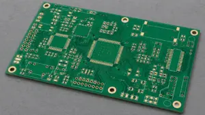
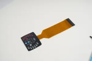
- Copper FPC Reflow Option for High-Density Panels: When a panel integrates 20+ diodes alongside backlit LEDs, upgrading the circuit layer to a polyimide PCB/FPC Membrane Switch allows standard lead-free SMT solder paste reflow for maximum joint strength.
|
Pre-RFQ DFM Checklist: 4 Rules for Electrical Schematic & Matrix Design • [ ] Default to Common-Bus Wiring for <= 12 Keys: If your MCU has enough GPIO pins (or uses an I2C GPIO expander like PCA9555), Common-Bus (N + 1) eliminates matrix scanning firmware and ghosting at zero extra component cost. • [ ] Isolate ‘EMERGENCY STOP’ and ‘START’ Keys From the Matrix: Even if your numeric keypad (0–9) uses an unisolated matrix, always route safety-critical START, STOP, or BOLUS keys on dedicated independent Common-Bus pins. • [ ] Size MCU Pull-Up Resistors Between 10 kΩ and 47 kΩ: Because screen-printed silver/carbon loops have 20–100 Ω closed contact resistance, avoid ultra-low pull-up resistors (<1 kΩ); 10 kΩ at 3.3 V yields a clean <0.03 V logic-low level. • [ ] Implement a 10–15 ms Software Debounce Filter: Crisp stainless steel tactile domes exhibit <2–5 ms mechanical contact bounce; a 10–15 ms state-machine debounce guarantees rock-solid single keystrokes. |
Frequently Asked Questions (FAQ)
Q1: At what key count does a Row-Column Matrix make more sense than Common-Bus wiring?
Common-Bus (N + 1 pins) is ideal up to 10–14 keys. Once your keypad reaches 15 or more keys (for example, a 16-key 4 × 4 or 20-key 4 × 5 layout), matrix wiring cuts your tail width and ZIF connector pin count in half.
Q2: Can two keys be pressed at the same time on a standard matrix without diodes?
Yes, any 2 keys can be pressed simultaneously without ghosting. Ghosting only occurs when 3 or more keys that share rows and columns on three corners of a grid rectangle are held down at the exact same moment. Alternatively, we can route ‘modifier keys’ (like SHIFT or FN) on dedicated independent pins while keeping the remaining keys in a standard matrix.
Q3: What is the maximum loop resistance of a screen-printed silver membrane switch?
Standard closed-loop contact resistance across a printed silver/carbon membrane switch trace is <50 Ω to 100 Ω (depending on tail length and trace width). If your circuit requires <1 Ω loop resistance, specify our PCB/FPC Membrane Switches with etched copper traces and gold-plated metal domes.
Let Our Engineers Optimize Your Keypad Matrix and Pinout
Not sure whether your interface needs Common-Bus wiring, a hybrid modifier matrix, or embedded SMD blocking diodes? Use our instant Membrane Switch Cost Estimator or send your button layout to our engineering team via Request a Quote for a complimentary schematic proposal.
Ready to Start Your Project?
Tell us about your membrane switch, keypad, or graphic overlay requirements. Our engineering team will review your specifications and provide a detailed quote.