Quick answer: An industrial keypad design checklist covers eight items — IP rating per IEC 60529, overlay material and chemical compatibility, gloved actuation force (250–500 g), backlight strategy, electrical interface and EMI shielding, mounting tolerance, compliance with UL 969 / IEC 61010 / EN ISO 13849-1, and a verified lifecycle of at least 1 million actuations under IEC 60068-2-6.
A machine-control keypad spec that misses one of the eight items below typically surfaces after first-article inspection, when the overlay swells under flood coolant or the LED bezel fogs at 0 °C. By then the panel cutout is already in the CNC sheet-metal queue and the change order eats two weeks. The framework here is what controls engineers at OEMs in North America and Western Europe lock down before the membrane stack drawing leaves the design table.
- 1. Why an Industrial Keypad Design Mistake Costs More Than the Part Itself
- 2. The 8-Point Evaluation Framework
- 2.1 Environmental Ingress Protection (IP Rating per IEC 60529)
- 2.2 Overlay Material and Chemical Compatibility
- 2.3 Actuation Force and Tactile Feedback for Gloved Operators
- 2.4 Backlight Strategy and Legend Durability
- 2.5 Electrical Interface and EMI Shielding
- 2.6 Mounting, Sealing, and Panel Cutout Tolerance
- 2.7 Safety and Regulatory Compliance
- 2.8 Lifecycle, MTBF, and Supplier Qualification
- 3. The 6-Step Design-and-Sourcing Process
- Step 1 — Define the environment and duty cycle (Weeks 1–2)
- Step 2 — Lock the electrical interface to the PLC or HMI controller (Weeks 2–3)
- Step 3 — Issue the RFQ with a complete spec sheet (Weeks 3–5)
- Step 4 — Prototype review and first-article testing (Weeks 6–10)
- Step 5 — Pilot-run validation (Weeks 10–13)
- Step 6 — PPAP / first-article approval and ongoing SPC (Week 14+)
- 4. Pre-Tape-Out Printable Checklist
- 6. What to Do Next
1. Why an Industrial Keypad Design Mistake Costs More Than the Part Itself
The membrane switch market reached USD 5.94 billion in 2024 and is projected to grow at 6.6% CAGR through 2030 (Grand View Research, 2024). Machine-control keypads carry a unique risk profile inside that market: the keypad costs USD 12–80 per unit, but a field failure costs an order of magnitude more — service truck roll, downtime on a CNC center at USD 200–600 per hour, plus the warranty claim.
Three failure modes recur in OEM service data. Coolant ingress through an underspecified seal: a keypad rated IP54 fits a packaging line, but on a Haas VF-2 with a flood-coolant nozzle pointed at the operator panel the same part fails within 90 days. Overlay delamination from cleaning chemicals: IPA wipes are routine in food processing, and a polyester overlay without an autoclavable topcoat lifts at the legends within six months. Mis-actuation under work gloves: an office-grade dome rated 180 g registers ghost presses when a gloved hand brushes the panel.
The eight criteria below cover the decisions that, once frozen in the drawing package, are expensive to revisit.
2. The 8-Point Evaluation Framework
The criteria are ordered by how often they cause field returns, not by how often engineers think about them at concept stage. Ingress protection tops the list; lifecycle, despite being the headline spec on most data sheets, sits at position eight because almost every reputable supplier meets a 1 M-actuation floor.
2.1 Environmental Ingress Protection (IP Rating per IEC 60529)
IP rating is the single decision that drives membrane stack, edge seal, and bezel geometry. IEC 60529 defines the two-digit IP code: first digit covers solids (dust), second covers liquids. For a CNC machine center with flood coolant, IP65 is the floor; IP67 is the working answer for any panel inside the splash zone; IP69K applies to washdown environments in dairy, meat, or pharmaceutical equipment per ISO 20653. UL 50E mirrors these classes for North-American panel enclosures under NEMA 4 / 4X / 6P language.
Each step up changes the seal architecture:
| Environment | Minimum IP rating | NEMA equivalent | Seal architecture |
|---|---|---|---|
| Indoor packaging line, no splash | IP54 | NEMA 12 | PSA gasket, vented |
| General factory floor, occasional splash | IP65 | NEMA 4 | Die-cut PSA gasket |
| CNC flood-coolant splash zone | IP67 | NEMA 6 | Closed-cell PU gasket, 25–40% compression, sealed flex tail |
| Dairy / meat / pharma washdown | IP69K | NEMA 4X | Over-molded silicone bezel, ISO 20653 tested |
Good signal: Supplier ships an IP-test report from a third-party lab (Intertek, TÜV, SGS) with test fixture photos and the IEC 60529 clause numbers referenced. Red flag: “IP67-rated” claim with no test report, or a self-declared IP69K without ISO 20653 test conditions (80 °C water, 80–100 bar, 14–16 L/min, 4 angles).
2.2 Overlay Material and Chemical Compatibility
The graphic overlay is the surface the operator touches and the surface coolant attacks first. Three working choices: autotex polyester (~0.18 mm, e.g., Macdermid 3M 7755-equivalent grades), polycarbonate (~0.20 mm, lower chemical resistance), and PET with a hard topcoat for general industrial duty. For machine tools using semi-synthetic coolants (Blaser Vasco 7000, Castrol Hysol XF), autotex polyester with a hardcoat survives 50,000+ wipe cycles per ASTM F2357; PC overlays craze within 5,000 cycles in the same fluid. Hydraulic fluids, mineral oils, MQL aerosols, and IPA/ethanol cleaning each require a written compatibility statement from the overlay maker.
Good signal: Supplier provides a chemical-compatibility matrix listing each fluid the keypad will see (by trade name or chemical family) against the proposed overlay grade, with cycles-to-failure data. Red flag: Generic “industrial-grade” overlay claim with no named material grade and no compatibility matrix.
2.3 Actuation Force and Tactile Feedback for Gloved Operators
Office keypads target 100–180 g actuation force. Machine-control keypads with gloved operators target 250–500 g, with a snap ratio (peak force ÷ contact force) of 40–60% so the operator feels a positive click through a glove. Below 250 g, leather welding gloves trigger ghost presses; above 500 g, repetitive use causes operator complaints within a single shift. The force-displacement curve, not the single peak number, is the real spec — a curve with a sharp drop after the peak signals strong tactile feedback; a flat curve reads as mushy.
Good signal: Supplier delivers a force-displacement chart (5 samples minimum) per JIS B 7741 or supplier internal procedure, showing peak, contact, and return force values. Red flag: A single nominal actuation number (“220 g typical”) with no tolerance, no snap-ratio data, and no test glove specified.
2.4 Backlight Strategy and Legend Durability
Three backlight technologies compete: LED with light guide film (LGF), electroluminescent (EL) panel, and fiber-optic. LED-LGF is the default for new designs — 50,000-hour rated life at 25 °C, dimmable, no inverter — but adds 0.6–1.2 mm to stack thickness. EL stays useful for retrofits requiring uniform 1 mm-thin glow, but degrades to 50% brightness at 5,000–8,000 hours and needs a 60–200 Vac inverter that adds an EMI source. Legend permanence is governed by UL 969: the printed legend must survive a defined solvent wipe (typically IPA, ethanol, MEK) without smearing or contrast loss, validated by 10× back-and-forth wipes under 5 N load.
Good signal: Backlight uniformity tested at 4 points across each key (±15%) and a UL 969 label-permanence certificate naming the solvents tested. Red flag: Backlight spec with no uniformity data, or printed legend without a named UL 969 or IEC 60068-2-70 wipe-test result.
2.5 Electrical Interface and EMI Shielding
A machine-control keypad connects to the HMI controller through one of three interfaces:
| Interface | Cost | Max cable | Best for | Weakness |
|---|---|---|---|---|
| Matrix-decoded flex tail | Low | 0.3 m | Cost-sensitive panels with PLC GPIO | Long-wire EMI susceptibility |
| USB-HID (embedded MCU) | Medium | 1.5 m | Plug-and-play with HMI PCs | Adds MCU BOM cost |
| I²C / CAN | Medium-high | 5 m+ | Distributed I/O, multi-panel machines | Requires bus controller on host |
In environments with VFD-driven spindles and servo drives, the flex tail acts as an EMI antenna unless shielded. The standard mitigation: a grounded ground-plane layer in the membrane stack plus a shielded tail terminating in a Faraday gasket at the connector. Test to IEC 61000-4-2 (±8 kV ESD contact, ±15 kV air), IEC 61000-4-4 (EFT bursts), and IEC 61000-4-5 (surge).
Good signal: EMI/EMC report from a NVLAP-accredited or ISO/IEC 17025 lab covering ESD, EFT, and surge per the IEC 61000-4 series. Red flag: “EMI-resistant” marketing language with no test level, no test lab, and no specified standard clause.
2.6 Mounting, Sealing, and Panel Cutout Tolerance
The keypad sits on a sheet-metal panel cutout. Three mounting methods exist: pressure-sensitive adhesive (PSA, typically 3M 467MP or 468MP), closed-cell foam gasket with mechanical fasteners, and ultrasonic weld for plastic enclosures. PSA achieves IP65 if panel flatness is within ±0.3 mm over the keypad footprint; IP67 generally requires a gasket compressed 25–40% by a clamping frame. The cutout itself needs corner radii ≥ 1.5 mm to avoid PSA peel-back at the corners — square-cornered cutouts are the most common assembly-stage cause of leakage failures.
Good signal: Supplier issues a panel cutout drawing with flatness call-out (±0.3 mm), corner radius (≥ 1.5 mm), and surface finish (Ra ≤ 1.6 µm) all dimensioned and toleranced. Red flag: A keypad outline drawing with no flatness, no radius, and no surface finish — guarantees an integration-stage rework loop.
2.7 Safety and Regulatory Compliance
For North American OEMs, UL 50E (enclosures), UL 969 (label permanence), and UL 61010-1 (safety for measurement, control, and laboratory use) form the baseline. For Europe, IEC 61010-1 plus the EMC Directive 2014/30/EU plus the Low Voltage Directive 2014/35/EU apply, with CE marking declared by the OEM. If the keypad integrates an emergency stop, EN ISO 13849-1 sets the Performance Level — PLd or PLe for most machinery — and the E-Stop circuit must be dual-channel with a category 3 or 4 structure. RoHS 3 (EU 2015/863) and REACH SVHC compliance are non-negotiable for any keypad shipped into the EU.
Good signal: Declaration of Conformity listing each applicable directive and standard by number, with the test report file numbers cross-referenced. Red flag: “CE compliant” stamp without a Declaration of Conformity, or an integrated E-Stop with no EN ISO 13849-1 PL rating.
2.8 Lifecycle, MTBF, and Supplier Qualification
A reputable supplier specs 1–5 million actuations per key per IEC 60068-2-6 vibration plus cycle testing. Above 5 million, premium tactile domes (stainless steel embossed) are required. The supplier’s QMS is the bigger differentiator: ISO 9001:2015 is the floor, IATF 16949 is required if the OEM ships into automotive Tier 1/Tier 2, and ISO 13485 if the keypad ends up on a medical device. PPAP-capable suppliers handle automotive-grade onboarding; for pure industrial work, an APQP-lite first-article package is usually enough.
Good signal: Actuation-life test data filed against IEC 60068-2-6 with the failure criterion defined (e.g., contact resistance > 200 Ω), and an active ISO 9001:2015 certificate with a recent audit date. Red flag: “10 million actuations” claim with no test standard cited, or an ISO certificate with no issuing body or expired audit window.
3. The 6-Step Design-and-Sourcing Process
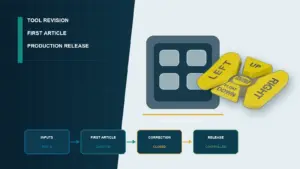
The framework above describes what to spec; the steps below describe when, mapped to a typical 12–16 week design cycle.
Step 1 — Define the environment and duty cycle (Weeks 1–2)
Write a one-page environment spec before sketching the keypad. Include: ambient temperature range (e.g., 0 to 50 °C), humidity range, IP target with justification, full list of cleaning agents and process fluids by trade name, daily actuation count per key, glove type if applicable, and panel mounting orientation. This sheet drives every downstream decision.
Step 2 — Lock the electrical interface to the PLC or HMI controller (Weeks 2–3)
Pick matrix-decoded, USB-HID, or I²C/CAN based on the controller’s available pins and the noise environment. Define the pinout, connector type (FFC, JST, Molex Picoblade are common), tail length, and shielding strategy here — switching from matrix to USB-HID at prototype review costs four weeks.
Step 3 — Issue the RFQ with a complete spec sheet (Weeks 3–5)
The RFQ package should include: a controlled outline drawing with all critical dimensions toleranced, the environment spec from Step 1, graphic artwork in Illustrator AI or PDF/X with Pantone callouts, the electrical schematic, a list of standards the keypad must meet (IEC 60068-2-1, UL 969, IEC 61000-4-2, etc.), and the test deliverables expected at first article. RFQs with all of this attached get accurate quotes; partial RFQs return a “TBD” placeholder on price.
Step 4 — Prototype review and first-article testing (Weeks 6–10)
First-article deliverables: 5–10 functional samples, the force-displacement curve set, the IP test report, the EMI/EMC pre-scan, the legend wipe-test result per UL 969, and a dimensional inspection report against the drawing with Cpk values for critical dimensions. Reject any first-article submission missing one of these and require a corrective-action plan.
Step 5 — Pilot-run validation (Weeks 10–13)
A 50–200 unit pilot run validates production tooling and ramps the supplier’s process control. Pilot units go into accelerated life test (temperature-humidity cycle plus vibration plus actuation cycling) and into operator usability trials on the actual machine. A pilot with a measured field-return rate below 0.5% over 60 days is the bar to clear before full production release.
Step 6 — PPAP / first-article approval and ongoing SPC (Week 14+)
Lock the production part approval — automotive-grade is full PPAP Level 3, industrial is typically PSW (Part Submission Warrant) plus dimensional and functional inspection reports. Establish ongoing SPC on the three most failure-prone dimensions (panel cutout interface, dome height, tail bond strength) with a Cpk floor of 1.33.
4. Pre-Tape-Out Printable Checklist
Items to confirm before signing off on the membrane stack drawing:
- [ ] IP rating selected against actual environment, not generic “industrial”
- [ ] IP test report from third-party lab (Intertek / TÜV / SGS) on file
- [ ] Overlay material grade named with chemical-compatibility matrix attached
- [ ] Cleaning agents listed by trade name in the matrix
- [ ] Actuation force window specified with tolerance (e.g., 350 ± 50 g)
- [ ] Force-displacement curve attached for 5 samples minimum
- [ ] Gloved-operator test performed if applicable
- [ ] Backlight type selected (LED-LGF / EL / fiber) with uniformity ±15%
- [ ] UL 969 legend wipe-test certificate on file
- [ ] Electrical interface defined (matrix / USB-HID / I²C / CAN) and connector P/N specified
- [ ] EMI/EMC report covering IEC 61000-4-2, -4-4, -4-5
- [ ] Ground plane in stack-up if EMI environment
- [ ] Panel cutout drawing issued with flatness ±0.3 mm, corner radius ≥ 1.5 mm
- [ ] Gasket compression 25–40% if IP67+
- [ ] UL 50E / NEMA enclosure rating documented
- [ ] EN ISO 13849-1 PL rating on file if E-Stop integrated
- [ ] RoHS 3 + REACH SVHC declarations attached
- [ ] Actuation lifecycle test per IEC 60068-2-6 with failure criterion defined
- [ ] Supplier ISO 9001:2015 certificate verified online
- [ ] First-article inspection package received, critical dimensions Cpk ≥ 1.33
5. Frequently Asked Questions
Q1. What’s a design checklist for an industrial machine control keypad?
Eight criteria: IP rating per IEC 60529, overlay material with chemical-compatibility data, gloved actuation force (250–500 g) with force-displacement curve, backlight strategy, electrical interface with EMI shielding per IEC 61000-4, panel mounting tolerance, regulatory compliance (UL 50E, UL 969, IEC 61010, EN ISO 13849-1 if E-Stop integrated), and 1 M+ actuation lifecycle per IEC 60068-2-6.
Q2. What IP rating do I need for a CNC machine membrane keypad?
IP65 is the floor for any keypad inside the machine enclosure. IP67 is the working answer for panels in the flood-coolant splash zone. IP69K applies to high-pressure washdown — dairy, meat, pharmaceutical equipment — and requires testing per ISO 20653 at 80 °C and 80–100 bar.
Q3. How do I make an industrial keypad oil- and coolant-resistant?
Specify autotex polyester overlay with a hardcoat rated for the named coolant trade name; require a chemical-compatibility matrix in the RFQ. Add an IP67 closed-cell polyurethane gasket compressed 25–40%. Seal the flex tail exit with a Faraday-style gasket and confirm 50,000+ wipe cycles per ASTM F2357.
Q4. How long does an industrial keypad design cycle take from concept to production?
A typical OEM cycle runs 12–16 weeks: 2 weeks environment spec, 1 week interface lock, 2 weeks RFQ and quote, 4 weeks prototype and first article, 3 weeks pilot validation, 2–4 weeks PPAP / first-article approval. Skipping the pilot stage cuts 3 weeks but raises field-return risk above 1%.
Q5. What’s the difference between a membrane switch and a silicone rubber keypad for machine controls?
A membrane switch is a flat polyester or polycarbonate stack 0.8–2 mm thick with embedded metal domes — ideal for sealed panels and harsh wipe-downs. A silicone keypad uses molded buttons protruding through a bezel — better tactile feel but harder to seal to IP67. Membrane switches dominate machine-control panels.
Q6. What actuation force should an industrial keypad use for operators wearing gloves?
250–500 g peak force with a 40–60% snap ratio. Below 250 g, leather welding gloves cause ghost presses; above 500 g, repetitive-use complaints arise within a single shift. Specify the force-displacement curve, not just the peak number, and validate with the actual glove type the operator will wear.
Q7. Does an industrial keypad need UL, CE, or both — and which matters first?
Depends on the destination market. North American OEMs require UL 50E and UL 969 first; UL 61010-1 if part of measurement or control equipment. European OEMs require CE marking under the EMC Directive 2014/30/EU and Low Voltage Directive 2014/35/EU, declared against IEC 61010-1. Most global suppliers test to both stacks in parallel.
Q8. What’s the typical actuation lifecycle for an industrial machine control keypad?
A polyester membrane switch with embedded stainless dome rates 1–5 million actuations per key per IEC 60068-2-6, with failure defined as contact resistance > 200 Ω. Premium domes reach 10 million at 1.5–2× the cost. Silicone keypads rate 500,000–2 million depending on carbon-pill grade.
6. What to Do Next
Lock the eight criteria above into the project’s design-input document before the panel cutout drawing leaves engineering. The printable checklist in §4 prints cleanly on a single A4 or US Letter page; treat it as the gate review before tape-out. For the RFQ stage, attach the environment spec, the controlled outline drawing, the named chemical list, and the standards list — RFQs sent with all four return accurate quotes within five business days from any tier-1 supplier.
Disclosure: The technical reference is authored by JASPER Electronics, an industrial membrane keypad manufacturer. The 8-point framework above is product-neutral; any supplier — including JASPER — should be evaluated against the same criteria before tape-out.
Ready to Start Your Project?
Tell us about your membrane switch, keypad, or graphic overlay requirements. Our engineering team will review your specifications and provide a detailed quote.