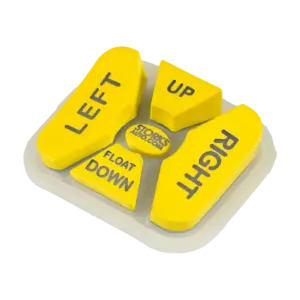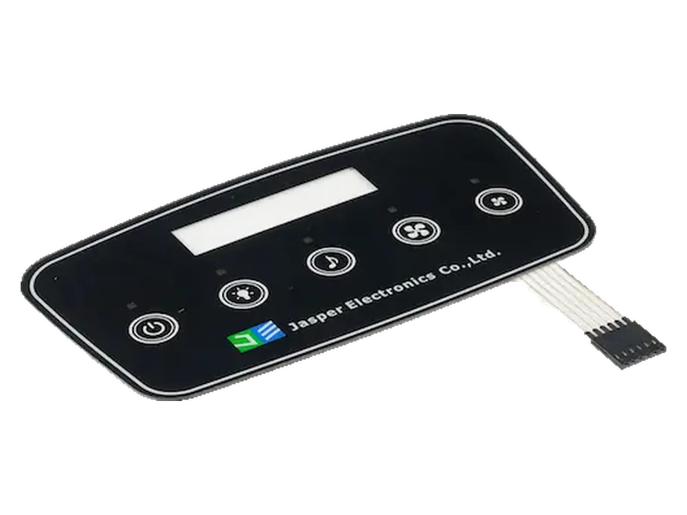
Choose flat capacitive touch when a continuous front surface and no-travel operation fit the task. Choose silicone contact keys when shaped key locations, physical travel, and mechanical feedback matter. These are starting points, not universal winners: Boyd’s construction examples distinguish flat capacitive stacks from elastomer keypads with contacts or domes.
For a capacitive touch vs silicone keypad decision, compare complete installed assemblies—not simply glass against rubber. The useful question is whether the operator can find the intended control, issue the correct command, recognize acceptance, and release it reliably.
Define the Keypad Construction Before Comparing
Compare a flat, fixed-function capacitive keypad with a mechanically operated silicone keypad assembly. A coordinate touchscreen is a different comparison.
The capacitive option uses defined electrodes behind a dielectric cover, with sensing electronics and firmware interpreting touch states. The silicone option uses molded keys with conductive pills that bridge contacts, or actuators that operate separate domes or switches. Epec’s silicone-keypad overview explains the deforming web and conductive-pill mechanism; silicone material alone does not define the switching method.
Use this comparison only with those construction assumptions:
| Decision factor | Flat fixed-function capacitive keys | Silicone contact or actuator keys |
|---|---|---|
| Input mechanism | Capacitance change at defined sensing zones | Mechanical movement closes a contact or operates a switch |
| Travel and feedback | No inherent key stroke or snap; specify electronic confirmation | Travel and return depend on molded geometry and switching stack |
| Finding keys without looking | Test locating a target without issuing an unwanted command | Test raised shapes, spacing, and orientation with the intended operator |
| Cleaning review | Examine the continuous face, perimeter, windows, and bond | Examine key shoulders, recesses, coatings, and enclosure joints |
| Lighting review | Coordinate icons, electrodes, optical paths, and LED wiring | Coordinate legends, translucent areas, contacts, and light barriers |
| Installation review | Control cover bonding, sensor support, nearby metal, and cable route | Control bezel clearance, key stroke, circuit support, and flange clamping |
| Electronics review | Define sensing, tuning, firmware, and host interface | Define contact limits, input scanning, debounce, and host logic |
| Replacement review | Specify sensor, cover, controller, and configuration compatibility | Specify mat, actuator/contact, circuit, and enclosure compatibility |
For sourcing, review custom capacitive touch panels and silicone rubber keypads at the same delivery boundary: separate components or an agreed functional assembly. State the included parts in the quotation.
Evaluate Travel and Operator Feedback
Separate locating the key, feeling its movement, and confirming the accepted command. One successful step does not prove the others.
Silicone-key geometry provides variables for tactile design, rather than one standard feel. Epec’s rubber-keypad design guide distinguishes web construction, travel, force, and tactile characteristics. Request a force–displacement measurement with the closure and release points identified. Record the fixture, press location, loading method, sample revision, and whether the keypad was installed in its intended enclosure.
Compare center and off-center presses, repeated commands, sustained holds, and complete return. Include the actual glove models and working posture. A sample that feels acceptable between two fingers may not demonstrate the installed behavior needed for a handheld or wall-mounted control.
For flat capacitive keys, do not specify a mechanical actuation force as a substitute for touch performance. Define the confirmation method and measure the sequence from touch detection to host acceptance and feedback. Added vibration requires a feedback system; capacitive sensing itself does not generate a click.
For eyes-off operation, ask representative operators to locate, activate, hold, and release the required keys while attending to their primary task. Record wrong-key selections, missed commands, unintended repeats, and unnecessary glances. Test whether exploring the flat surface triggers commands before the intended key is found. Keep safety-related functions subject to the equipment’s separate safety design; neither ordinary keypad feel nor touch detection establishes safety suitability.
Compare Graphics, Lighting and Surface Cleaning
Approve appearance and cleaning on the finished stack, not from the surface material name. Specify lit, unlit, and cleaned conditions before sample review.
For capacitive controls, the cover, ink, adhesive, and air gaps participate in the sensing stack. TI’s CapTIvate design guide explains these mechanical–electrical relationships and identifies LED-drive signals as possible interference sources. Review sensing with the intended lighting states, not only with LEDs disconnected.
For silicone controls, illuminated legends can use laser-defined graphics; Epec’s specialty-keypad reference provides examples of that construction. Specify the selected decoration, translucent regions, and light-blocking features rather than assuming every rubber key transmits light appropriately.
Compare icon alignment, contrast, light leakage, hotspots, and viewing angle on assembled alternatives. Save the artwork revision, lighting configuration, inspection conditions, and approved appearance sample.
A continuous face is a useful starting point for wiping, but compare its perimeter and window joints against the actual molded-key geometry. Define the cleaning agent, concentration, exposure, wiping method, and repetition schedule. Inspect discoloration, coating or legend damage, residue, and loss of function afterward. Where wiping could issue commands, specify and test a cleaning lockout. Easy wiping is not evidence of validated disinfection or chemical compatibility.
Review Sealing, Mounting and Electronic Responsibilities
Treat enclosure sealing, installed mechanics, and command recognition as separate approvals. None can be inferred from a front-view photograph.
IEC 60529 classifies protection provided by enclosures. An enclosure IP rating is therefore not evidence that wet keys recognize commands correctly. Specify the assembled seal boundary and separately test intended input, unintended activation, release, and recovery under the relevant operating conditions.
For silicone, request a section through the bezel, key web, contact or actuator, circuit support, and clamped perimeter. Dimension free travel and clearances. Check for contact preload, rubbing, and incomplete return at assembly tolerance limits. Document any required pressure-relief path without creating an unreviewed opening through the environmental seal.
For capacitive, document cover support and bonding, sensor alignment, nearby conductors, and the tail route. Reserve room for the actual electronics and lighting rather than assuming no key travel means no rear packaging depth.
Allocate six responsibilities explicitly: cover and decoration; sensor or contact circuit; controller or switch-input hardware; firmware; display and feedback hardware; host command behavior. Name the supplier, integration owner, and acceptance evidence for each. A display window is not a supplied display.
For silicone contacts, agree acceptable closure resistance and scan/debounce behavior. For capacitive inputs, state whether the connection carries raw electrode signals or processed output. Boyd’s guide illustrates different controller locations and assembly boundaries; do not assume the physical-panel supplier also owns firmware.
Repeat functional checks in the powered product with its intended display, lighting, supply, and loads. The custom capacitive touch panel design guide provides the broader drawing and validation framework; here, use it to identify what changes when switching from silicone contacts.
When a Hybrid Construction Makes Sense
Combine silicone and capacitive sensing only when the combination solves a defined operator task. The words “silicone” and “capacitive” describe different attributes, not mutually exclusive categories.
In principle, a suitably specified nonconductive silicone surface can form part of the dielectric stack above capacitive electrodes. This follows the material-and-gap design principles in TI’s guide, which includes silicone among evaluated gap-bridging materials; it is not proof that an existing key mat will work unchanged.
A molded locator surface may help the operator find a target, but does not automatically supply travel or snap. A moving tactile construction introduces another question: does sensing occur on initial contact, during partial movement, or only at the intended actuation point? Test resting, exploratory contact, partial presses, full presses, and release.
By contrast, a silicone actuator over a membrane contact or metal dome remains mechanically switched. Calling it “hybrid” does not make it capacitive. Record the compound, conductive features, rest/pressed geometry, sensing method, and intended event sequence. Request project-specific construction confirmation rather than assuming a standard silicone or hybrid offering includes capacitive sensing.
Choose a Route for Three Purchasing Tasks
Start with the requirement that cannot be compromised, then use prototype evidence to confirm or reject the route. These are illustrative selection paths, not customer results.
| Purchasing task | Starting route and decision branch | Evidence to retain |
|---|---|---|
| Source fixed controls operated without looking, with specified gloves | Start with shaped silicone keys. Retain the route only after locating, pressing, and releasing pass. Consider flat touch only when its locating and feedback strategy passes the same tasks. | Key geometry, glove identity, installed feel, wrong-key and missed-command records |
| Source a wipe-clean front with illuminated fixed icons | Start with flat capacitive keys when no-travel operation is acceptable. Retain them only after cleaning, lighting, and input-state checks pass. Evaluate a sealed silicone assembly when mechanical feedback remains necessary. | Surface and cleaning specification, lit/unlit approval, event logs, seal evidence |
| Refresh an existing silicone control while retaining the PCB and housing | First evaluate a mechanically and electrically compatible silicone replacement. Treat conversion to capacitive sensing as a redesign unless circuit, power, mounting, and firmware compatibility are demonstrated. | Interface drawing, contact/input limits, compatibility results, service-unit definition |
Approve the chosen route with one comparison record. Illustrative template: leave results blank until testing, and attach the sample ID, stack revision, firmware, enclosure, test conditions, and agreed acceptance limits.
| Check | Condition to define before testing | Actual result |
|---|---|---|
| Locate and select | Operator task, posture, glove, permitted visual attention | |
| Activate, hold, release | Input method, timing, repeat behavior, feedback state | |
| Clean and recover | Agent, method, lockout, recovery requirement | |
| Replace and retest | Replacement unit, assembly procedure, seal and functional checks |
Frequently Asked Questions
These questions address compatibility, quotation, and approval details that should be resolved before committing to the construction.
Can a silicone keypad reuse our existing PCB?
Possibly, after checking the contact pattern, pill or actuator alignment, support height, electrical input limits, and scan behavior. A matching outline is insufficient. Approve the replacement with the actual PCB and enclosure, including reliable closure and release at the agreed assembly tolerances.
Does capacitive touch eliminate the need for debouncing?
No. It removes mechanical contact bounce from the sensing element, but capacitive state changes may still need qualification against noise. TI’s debounce documentation describes qualifying entry and exit over multiple samples, with a response-time tradeoff. Specify touch, release, and host-event timing separately.
Can illuminated legends disappear when the controls are off?
Potentially, but “backlit” does not automatically mean “hidden when unlit.” Request paired illuminated and unilluminated samples under defined ambient light and viewing angles. Approve background contrast, legend visibility, light leakage, and readability together rather than accepting only a photograph taken in darkness.
Will matching Shore hardness reproduce our current key feel?
No. Hardness alone does not define the installed force–travel behavior. Compare web geometry, travel, contact or dome arrangement, and mounting support. Use the dimensions and tactile variables identified in the rubber-keypad design reference, then approve a physical sample and its measured response.
How should we compare quotations for the two constructions?
Ask both suppliers to price the same functional boundary and quantity schedule. Separate tooling, molded or printed parts, circuits, controller and firmware work, lighting, assembly, validation, and service parts. Record exclusions and change costs; a loose key mat and a programmed front-panel assembly are not equivalent quotations.
Can the controls remain usable if an indicator or sound fails?
Treat this as a defined fault-state test. A mechanical snap can confirm key movement but not successful host execution. Specify which actions remain available, what alternative confirmation exists, and which functions must be inhibited. Test the agreed behavior instead of assuming tactile or electronic feedback is sufficient.
What should the service-replacement specification include?
Define the replaceable unit, approved material and hardware revisions, connector and pinout, firmware compatibility, and any required setup after installation. Include seal restoration and a post-replacement functional check. State whether service replaces a rubber mat, a contact board, a sensor, or the complete front assembly.
Review Your Keypad Requirements
Submit the operator task and assembly constraints together so the two routes can be compared fairly. Include the key layout, enclosure section, current PCB/contact drawing or controller plan, connector and pinout, target feel, glove models, cleaning conditions, lighting states, expected quantities, and replacement requirements. Identify which electronics, firmware, display, and host functions are buyer-supplied.
Ready to Start Your Project?
Tell us about your membrane switch, keypad, or graphic overlay requirements. Our engineering team will review your specifications and provide a detailed quote.