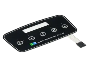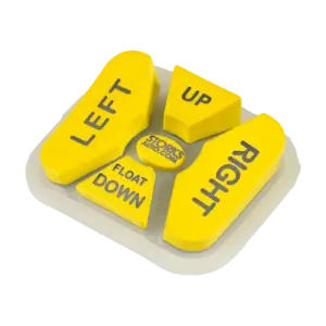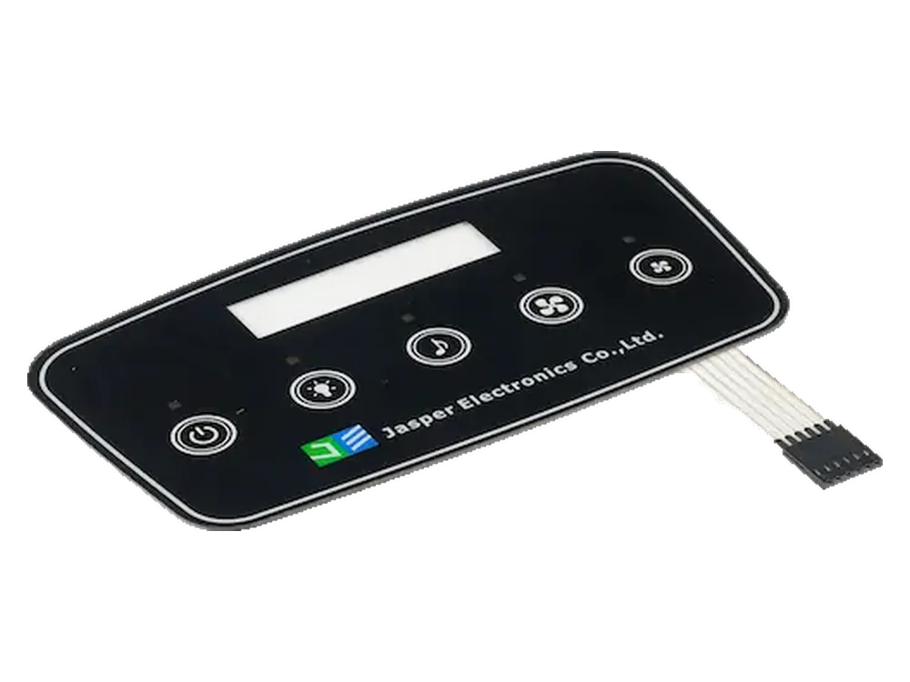
For an OEM redesign, evaluate capacitive touch where a continuous control face is valuable; retain suitable mechanical buttons where deliberate physical operation, eyes-off location, or individual replacement is essential. A mixed layout should remain an option. Choose by function, not by whether the new panel looks more modern.
This capacitive touch vs mechanical buttons comparison concerns fixed-function capacitive keys and separate enclosure-mounted pushbuttons. It does not compare membrane-switch constructions or coordinate-reporting touchscreens. The decision includes the existing enclosure, electrical interface, host behavior, and service procedure—not just the visible button.
- Identify Which Functions Need Deliberate Actuation
- Compare Feedback and Mounting Requirements
- Resolve every existing hole
- Separate input feedback from equipment status
- Include Host Electronics and Power States
- Plan Field Replacement and Maintenance
- Separate Routine Controls from Safety Functions
- Review Your Control Panel Redesign
Identify Which Functions Need Deliberate Actuation
Start with what each existing button actually does, including what must not happen. Preserve its intended behavior before changing the sensing method.
Record the contact arrangement, momentary or maintained action, and whether the button or host stores the operating state. Manufacturer switch fundamentals distinguish momentary operation from alternate operation; matching the legend alone does not establish equivalent behavior.
Then document when a command occurs: on press, release, sustained actuation, or repeated input. Identify the consequences of a missed command, an extra command, and an input received while the equipment is unavailable.
Illustrative function-allocation worksheet—not a safety design or a record of tested results.
| Existing function | Input method to evaluate | Behavior to validate |
|---|---|---|
| Open a status page | Fixed capacitive key candidate | One intended event; incidental contact or cleaning must not open unintended functions. |
| Repeated routine value adjustment | Mechanical button, capacitive key, or hybrid | Individual steps, intentional repeat, release termination, and operator correction effort. |
| Request a routine process start | Candidate chosen after risk review | Deliberate request, disabled-state handling, and distinct acknowledgment of host acceptance. |
| Wake a standby interface | Input compatible with the power architecture | Availability in standby; whether the first input wakes only or also requests an action. |
| Select a retained operating mode | Suitable maintained control or explicitly defined host state | Visible state, power-loss behavior, and consistency after controller or host restart. |
| Emergency stop, interlock, or safety-related enabling | Separate safety-engineered system | Outside ordinary touch-key substitution; qualified safety review required. |
For frequent operation, compare representative work sequences on both mockups. Include the actual glove constructions and sizes, hand position, approach angle, and eyes-off tasks. Record misses, unintended activations, hesitation, repeat overshoot, and fatigue—not merely successful detection. Set acceptance criteria before the trial.
A useful redesign question is whether removing travel reduces operator effort or instead adds aiming and visual-checking effort. Do not treat a sensitivity adjustment or a long-press rule as proof of deliberate operation.
Compare Feedback and Mounting Requirements
Compare two complete installed solutions, not a bare mechanical switch against a finished touch assembly. Include mounting, sealing, connections, required signal conditioning, feedback, and host changes in both proposals.
Use the following as a comparison worksheet, not a universal performance ranking. Resolve each entry against the selected components and assembled prototypes.
| Decision boundary | Individual mechanical pushbuttons | Fixed capacitive keys |
|---|---|---|
| Operator action | Specify actuator shape, force, travel, and return or maintained action. | Specify active zones, touch/release behavior, and rejection of incidental contact. |
| Feedback | Evaluate physical feel and any illumination; neither establishes host acceptance. | Specify visual, audible, or separately engineered haptic feedback and its meaning. |
| Enclosure interface | Review each cutout, mounting device, gasket, and terminal clearance. | Review the cover, support, bond, perimeter seal, sensing stack, and cable exit. |
| Electrical interface | Verify contact configuration, load suitability, and host input conditioning. | Verify sensing electronics, supply, output interface, and host integration. |
| Gloves and eyes-off use | Test identification and actuation with the selected actuator and gloves. | Test location and activation through the actual glove and cover combination. |
| Repeated use | Assess operating effort and qualified contact/actuator endurance. | Assess task effort, surface condition, bonding, electronics, and event behavior. |
| Field service | Establish whether an operator, contact block, or complete button is replaceable. | Establish whether a sensor, controller, removable module, or bonded front is replaceable. |
Resolve every existing hole
Choose deliberately between retaining selected buttons, closing unused holes with an engineered conversion plate, or replacing the enclosure front. A graphic sheet over empty cutouts does not by itself establish structural support or sealing.
Produce an old-to-new drawing that identifies retained holes, covered openings, supporting lands, fastening, gasket or adhesive paths, and the tail or harness exit. Check rear access and nearby metal before committing to the electrode layout.
Texas Instruments’ CapTIvate design guide explains how cover materials, thickness, bonding, and air gaps affect capacitive sensing. An inherited hole pattern is therefore a mechanical constraint, not validated sensor artwork.
For custom capacitive touch panels, define the conversion plate and sensing stack together. Use the custom capacitive touch panel design guide for the detailed drawing package rather than treating the new face as an artwork-only change.
Separate input feedback from equipment status
Define separate indications for detection, accepted command, and actual equipment state. In the mockup review, ask operators what each click, light, sound, or vibration means. Specify any required haptic actuator and drive electronics separately from capacitive sensing.
Keep environmental claims separate too. Manufacturer protection-rating guidance describes ingress protection, not a wet-touch acceptance test. Record enclosure leakage and input behavior as different verification results; neither establishes arbitrary glove compatibility.
Include Host Electronics and Power States
Treat the redesign as an electrical and behavioral interface change, even when the front-panel labels stay unchanged.
A mechanical contact can change position without a sensing supply, although the receiving circuit needs power to interpret it. A capacitive channel requires powered sensing electronics. Identify whether the original button handles a control signal, switches a power circuit, or serves an isolating function; these are not interchangeable roles.
Compare the old circuit and proposed output for voltage, polarity, reference, pull-ups, isolation, input conditioning, and failure behavior. A raw electrode is not a host-ready switch output. Manufacturer switch application guidance also distinguishes contact bounce and load suitability: neither an unconditioned contact nor an unqualified logic output is automatically equivalent to the old input.
The Microchip AT42QT1010 datasheet documents a power-on interval when its output is invalid and a maximum-on behavior that triggers recalibration. These are device-specific examples—not universal timings or a recommendation of that controller for this redesign.
Write a power-state test sequence covering full power-off, standby, sensing startup, host startup, interrupted supply, and independent host/controller restarts. Check a finger already present at startup and a command held through a transition. Specify when input becomes valid, whether release and fresh actuation are required, and what happens to pending or repeated commands. A wake key needs a sensing path that remains powered in the intended standby state.
Assign ownership explicitly: the cover owner controls the mechanical stack; the sensor owner controls electrodes and routing; the controller owner specifies electrical detection; firmware defines filtering and event behavior; the display/indicator implementation renders feedback; and the host decides whether to accept and execute commands. One supplier may cover several roles, but the handoffs still need definitions.
For every disputed response, trace the entire chain:
Physical actuation → detected state → conditioned press/release event → host acceptance or rejection → equipment response.
Illustrative test-record fields: control ID; hardware and firmware revisions; power state; intended action; detection, release, acceptance, and feedback timestamps; equipment outcome; pass/fail against the agreed requirement. Leave observations blank until tested. Measure feedback at its actual point in the chain rather than assuming it proves completion.
Plan Field Replacement and Maintenance
Select the replaceable unit before approving the new panel construction. “No moving contacts” is not a service plan.
Some OMRON panel-button families have separable operators and switch units. Do not assume all mechanical buttons share that construction, or that a bonded touch front offers the same repair boundary.
Compare a single-button fault with a shared sensor, controller, or interconnect fault. During a service trial under the OEM’s isolation procedure, document access, diagnosis, removal, replacement, resealing, configuration recovery, and checks of every affected control. Record tools, consumables, technician effort, and downtime. A removable touch module may offer a different service trade-off from a permanently bonded front; specify the actual proposal.
For repeated-duty claims, distinguish a switch’s mechanical endurance from electrical endurance under specified loading, as described in the manufacturer’s durability guidance. Request conditions and assembly-level evidence rather than comparing an isolated cycle figure with a general “wear-free” claim.
Include spare-part identifiers and compatible cover, sensor, controller, firmware, and host revisions in the service package. Where the redesign involves HMI assembly, define the physical supply scope separately from firmware, host integration, and equipment validation responsibilities.
Separate Routine Controls from Safety Functions
Do not directly replace an emergency stop, interlock, or other safety function with an ordinary capacitive key. An ordinary mechanical button is not automatically suitable for a safety function either.
A routine stop request and an emergency-stop function require separate treatment. The public scope of ISO 13850 addresses emergency-stop design principles; ISO 13849-1 addresses safety-related parts of control systems. Neither makes a generic input technology sufficient by itself.
Have qualified machinery-safety engineering identify affected functions and evaluate changes to actuation, power, software, failure behavior, and shared components under the applicable requirements. Keep safety-related enabling, reset, or hold-to-run functions outside the ordinary comparison until their role is established. Record the review owner and approval boundary; do not treat this article or a panel quotation as safety validation.
Frequently Asked Questions
Resolve these implementation questions before treating the redesign as a drop-in replacement.
Can the existing enclosure be reused?
Possibly. Assess an adapter plate or replacement front against the existing hole pattern, structural support, sealing path, sensing layout, and rear access. Reusing the enclosure does not establish that its original protection rating still applies.
Can the original button wiring stay in place?
Only after interface review. Compare the old contact circuit with the proposed controller output, including voltage, polarity, reference, isolation, and fault behavior. A sensor electrode connection is not a replacement for a dry-contact pair.
Does holding a finger on a touch key reproduce a maintained button?
Do not assume it does. Specify whether the host needs a held signal, a toggle, or a stored operating state, then verify the selected controller and firmware. Test release, interruption, and restart as well as sustained contact.
What should the first touch after standby do?
Define whether it only wakes the interface or also requests an action. Show that state clearly and test the complete wake sequence. Do not leave this decision to an undocumented interaction between controller firmware and host software.
What should be checked when the key lights up but nothing happens?
First identify what the light represents. In a controlled test, compare the detected input, transmitted event, host acceptance, and equipment response. A local indicator should not be treated as confirmation that the equipment executed the command.
Can only some of the mechanical buttons be replaced?
Yes, a hybrid layout is a redesign option. Evaluate touch keys for selected routine functions while retaining suitable physical controls where operation or service requirements favor them. Review the combined mounting, feedback, wiring, and safety boundaries.
Which costs belong in the RFQ comparison?
Compare the complete installed solution: enclosure changes, input hardware, electronics, firmware integration, feedback, validation, assembly, and service spares. Separate development costs from recurring unit costs, and identify which failed part requires replacement in each proposal.
Review Your Control Panel Redesign
Submit the existing installation as well as the proposed front-panel design. Include cutout drawings and photographs, the original circuit and function list, proposed input allocation, cover and display arrangement, host interface and power states, prototype and production quantities, operating and cleaning conditions, and field-replacement requirements.
Review My Control Panel Redesign to request a scope-specific discussion of the panel requirements. Identify which mechanical, electronic, software, and validation responsibilities the quotation should include.
Ready to Start Your Project?
Tell us about your membrane switch, keypad, or graphic overlay requirements. Our engineering team will review your specifications and provide a detailed quote.