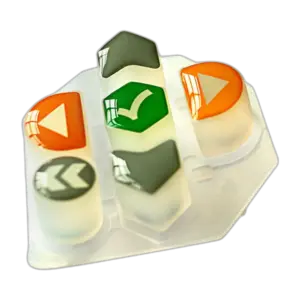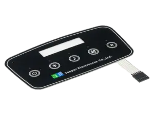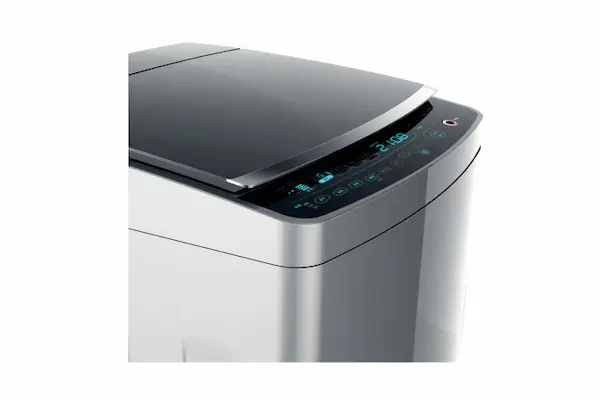
Start backlit capacitive touch panel design with an icon-state map, then coordinate the graphics, electrodes, optical path and LED drive around that map. Approve the installed assembly with lighting both on and off—not simply a panel that lights up on a bench.
This guide addresses fixed-function touch keys. Its acceptance records concern touch detection, press/release events and host commands, not the coordinate accuracy or multitouch performance of a projected-capacitive touchscreen. Keep any display qualification separate.
For a combined interface project, start with custom capacitive touch panels and define which physical parts and electronics belong in the quotation.
Define Which Icons Light Up in Each State
Specify what each illuminated symbol means before deciding how many LEDs to install. Separate an available command, an accepted command and a status-only indication.
Use the following illustrative map as a starting point. The modes are examples, not prescribed colors, timing or brightness levels.
| Icon | Equipment state | Lighting mode | Touch zone and behavior | Acceptance condition |
|---|---|---|---|---|
| Power | Standby | Steady standby level | T01; wake input enabled | Icon recognizable; wake event matches specification |
| Mode | Available | Steady available-state color | T02; selection enabled | Correct icon and channel mapping |
| Mode | Selection accepted | Change to selected-state color | T02; host-defined behavior | Change follows host acceptance within agreed delay |
| Lock | Cleaning lockout | Steady lock indication | Status only; operating commands rejected | Lock visible; rejected contacts do not show acceptance feedback |
| Service | Service required | Specified pulse pattern | Status only; no associated key | Pattern correct; neighboring icons remain within off-state limits |
| All icons | Power removed | Off | Electronics unpowered | Background, icon visibility and print match approved unlit reference |
Add boot, shutdown, sleep, rejected-input and fault states as relevant. For every row, record the LED channels, color reference, brightness setting, transition timing, initiating event and firmware revision. Specify any allowed simultaneous touches separately.
For illuminated capacitive touch buttons, also state whether feedback means “contact detected” or “equipment command accepted.” Do not use those meanings interchangeably. Define a powered-but-dark state separately from power removed, including whether a hidden wake target remains active.
Ordinary touch keys and their lighting should not be specified as substitutes for independently assessed safety functions.
Coordinate Graphics, Electrodes and Optical Layers
Develop the artwork, sensor and lighting geometry against one assembly datum. Record icon boundaries, touch targets, light openings and alignment tolerances as separate drawing layers.
TI’s CapTIvate design guidance cautions against copying decorative icon shapes into electrodes and against oversized backlighting holes that create sensing dead spots. A brighter opening is not automatically a better touch target.
Use this functional checklist when comparing constructions. It is not a mandatory stack order; some functions may share a component.
| Layer or feature | Role in the design | What to compare or record |
|---|---|---|
| Printed cover and translucent icon ink | Present graphics and define the light-transmitting image | Material, print revision, finish, lit color and unlit appearance |
| Opaque mask and optical partitions | Restrict unwanted light paths | Pinholes, border overlap, partition location and compressed height |
| Sensor with apertures or transmitting regions | Accommodate sensing and the required light path | Electrode geometry, openings, registration and local touch response |
| Light guide | Distribute light from its entry region toward the icons | LED coupling, extraction pattern, orientation and bonding keepouts |
| Diffuser | Redistribute incident light | Diffusion characteristics, orientation and assembled appearance |
| Reflector, where used | Redirect light within the optical cavity | Placement, material identity and electrical suitability |
| Adhesive and spacer system | Locate and support the assembly | Thickness tolerance, cutouts, compression and bond condition |
Boyd’s capacitive-touch guide identifies discrete LEDs and light-guide films as possible lighting approaches, with selection influenced by available space, power and illuminated area. Luminit’s diffuser documentation describes light redistribution and homogenization. These functions should be evaluated separately rather than treating every optical film as a light guide.
Trace the complete path from LED to icon. For an opaque PCB sensor, identify the actual opening through which light passes. For another sensor construction, confirm which regions transmit light. Adding a diffuser behind an opaque obstruction does not remove that obstruction.
Keep optical cavity depth distinct from sensor-to-cover spacing. Microchip AN2934 explains that increasing cover distance reduces touch coupling; TI also identifies unintended air gaps as a stack-up concern. Do not create extra sensor separation solely to make room for lighting without reassessing touch performance.
Document conductive inks or reflective films for sensor review; an optical reflector is not automatically an electrical shield.
Use the graphic overlays page for the printed-face portion of the project. Specify its optical requirements together with the sensor assembly rather than approving the artwork in isolation.
Place LEDs and Manage Light Leakage
Choose LED placement from the illuminated area and independently controlled states, then compare feasible constructions in the available enclosure depth.
For each candidate, prototype the real icon artwork and optical stack. Compare a direct lighting path with a guided path where both are feasible, recording LED part numbers, current, supply and mechanical dimensions. Judge the finished icon, not an exposed LED.
Start isolation checks with one icon illuminated and its neighbors commanded off. Repeat with adjacent colors, all permitted simultaneous icons, and the brightest specified mode. Inspect from the required viewing positions and examine the bezel, display window, seams and panel edges.
When leakage appears, identify the route before changing the drawing: through insufficiently opaque print, around a partition, through a shared optical region or along an assembly gap. Record the location and lighting state with the defect photograph.
Evaluate the permitted alignment extremes, not just nominal CAD geometry. Shift the mask, sensor and LED positions through the agreed tolerance combinations and check minimum partition compression. An acceptable centered prototype does not establish acceptance at every allowed assembly position.
A brief uniformity check
Define measurement locations within each icon, including narrow strokes and regions near and far from the LED. Record luminance with a suitable instrument under fixed viewing geometry, ambient light, drive state and stabilization conditions. Agree the measurement aperture and any excluded border before comparing results.
A project may define uniformity as U = Lmin / Lmax across that agreed measurement set. This is a declared calculation convention, not a universal acceptance limit. Record absolute luminance and color as well: equal uniformity ratios do not establish equal brightness or legibility.
Review Electrical Drive and Touch Performance
Specify the supply and drive conditions for every required lighting state, including startup and maximum simultaneous loading. Keep current regulation distinct from brightness modulation.
TI’s LED-driver design paper distinguishes resistor-limited and constant-current drive and explains analog and PWM dimming. A constant-current driver can still use PWM; these are not mutually exclusive choices.
Record the supply range at the panel connector, LED part and bin, channel current, driver headroom requirement, dimming method, logic interface and connector allocation. Check component operating limits, current demand and temperature in the intended enclosure. For RGB icons, approve the combined color through the actual printed stack, not separate bare LEDs.
TI’s CapTIvate guide warns that LED control using a high-impedance off state can change the capacitance seen by the touch system. Specify the driver’s off-state behavior and review LED routes alongside sensor traces rather than assuming that “off” is electrically irrelevant.
Assign lighting-specific ownership: the cover supplier controls print and mask revisions; the sensor designer controls sensing geometry; the LED/driver owner controls power and channel behavior; the controller owner provides acquisition settings and diagnostics; the firmware/host owner defines event-to-light timing. The display owner must identify display operating states used during integration checks. Use the custom capacitive touch panel design guide to organize the wider system package.
If touch faults coincide with PWM dimming or lighting transitions, capture synchronized timestamps for LED channels, current settings, PWM frequency/duty cycle, supply, raw touch data, baseline, press/release events and host responses. Compare off, steady-on and dimming states before changing settings. TI identifies LED and digital routing as potential interference sources; timing correlation starts the investigation but does not prove its cause.
Approve Lit and Unlit Production Samples
Approve production-representative assemblies against written conditions and retained evidence. A cosmetic proof, an electrical prototype and a production sample should have clearly stated approval purposes.
Use the actual cover, print, optical parts, adhesive, sensor, housing and electronics for combined approval. Define the sample count and tolerance coverage in the project plan. Set criteria before inspection and retain deviations rather than silently accepting them.
The following checklist is reusable. Fill the agreed-condition fields and actual-result column for each sample or identified sample group.
| Check | Agreed condition or acceptance reference | Actual result / evidence |
|---|---|---|
| [ ] Sample identity | Sample ID; material, artwork, assembly and firmware revisions: ___ | ___ |
| [ ] Power removed | Ambient light, viewing angle/distance; permitted icon visibility; unlit master: ___ | ___ |
| [ ] Powered but dark | Supply and controller state; permitted residual glow or unintended indication: ___ | ___ |
| [ ] Each icon individually lit | Color, luminance, legibility and adjacent-icon leakage limits: ___ | ___ |
| [ ] Combined lighting states | Approved combinations; uniformity grid, metric and limits: ___ | ___ |
| [ ] Dimming and transitions | Minimum/maximum settings; pulse timing; boot, shutdown and reset behavior: ___ | ___ |
| [ ] Touch-to-light behavior | Required target locations; press/release, host acceptance and feedback timing: ___ | ___ |
| [ ] Installed operating conditions | Enclosure, display mode, supply, temperature and required user conditions: ___ | ___ |
| [ ] Production variation | Alignment/compression extremes, sample coverage and approved deviations: ___ | ___ |
| [ ] Release record | Photographs, measurements, logs, retained reference IDs and sign-off: ___ | ___ |
For unlit approval, state whether icons must disappear, remain faintly visible or remain readable. Do not use “dead-front” without agreed viewing conditions and a physical appearance reference.
For touch approval, retain no-touch observations as well as intended input tests across lighting states. Record missed, unintended, repeated or stuck events and whether host feedback was correct. Carry project-specific wet/glove conditions into this matrix without redefining them; the separate water and glove tuning guide addresses that work.
After approval, require review of changes to LEDs, inks, optical films, adhesive thickness, partitions, driver settings or firmware. Identify which checks must be repeated before accepting a substitute.
Frequently Asked Questions
Use these questions to resolve retrofit, approval and purchasing decisions before releasing the design.
Can an existing non-backlit sensor PCB be reused?
Possibly, but first check whether it provides an unobstructed light path without unacceptable changes to the electrode, routing or cover spacing. Compare the modified assembly with the original touch baseline before approving reuse.
Should a hidden icon remain touch-active?
Only when the interaction specification deliberately requires it, such as a defined wake function. Record illumination and command acceptance separately. For a locked control, verify command rejection rather than treating an unlit LED as evidence of lockout.
Can one shared light guide provide independent icon states?
Do not assume so. Require a prototype showing one icon lit while adjacent icons remain within their agreed off-state appearance limits. Compare segmented guides, optical partitions or separate lighting paths when independent states are essential.
Should higher LED current be the first response to a dim icon?
No. First inspect alignment, obstructions, print transmission and the selected optical stack. Consider a current change only within the LED and driver operating limits, then repeat power, temperature, appearance and touch checks.
Are phone photographs sufficient for supplier approval?
Use photographs to communicate defects and sample identity, not as the sole approval basis. Require controlled viewing conditions, a physical reference where practical, and instrument measurements for specified luminance or color limits.
What needs rechecking after an ink or diffuser substitution?
Review both illuminated and unilluminated appearance, icon isolation and installed touch behavior. Update material identities and stack revisions, then repeat the affected acceptance checks before approving the substitution.
What must two backlighting quotations have in common?
Compare the same icon-state map, optical stack, LED and driver scope, controller and firmware responsibilities, quantities, assembly boundary and acceptance plan. Identify prototype tooling, inspection fixtures and customer-supplied items separately before comparing totals.
Prepare a Backlit Icon Layout for Review
Submit the icon-state map together with the drawings and operating conditions—not only a request to add LEDs.
Include vector artwork, touch-zone IDs, enclosure sections and available depth; the proposed cover, sensor and optical stack; supply and driver details; controller/firmware responsibilities; lit and unlit appearance targets; viewing and operating conditions; prototype quantity and expected production volume. Mark unresolved decisions on the drawings so competing proposals can address the same requirements.
Ready to Start Your Project?
Tell us about your membrane switch, keypad, or graphic overlay requirements. Our engineering team will review your specifications and provide a detailed quote.