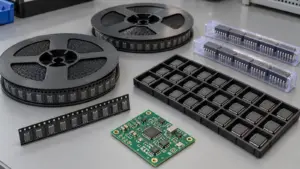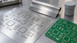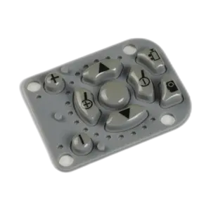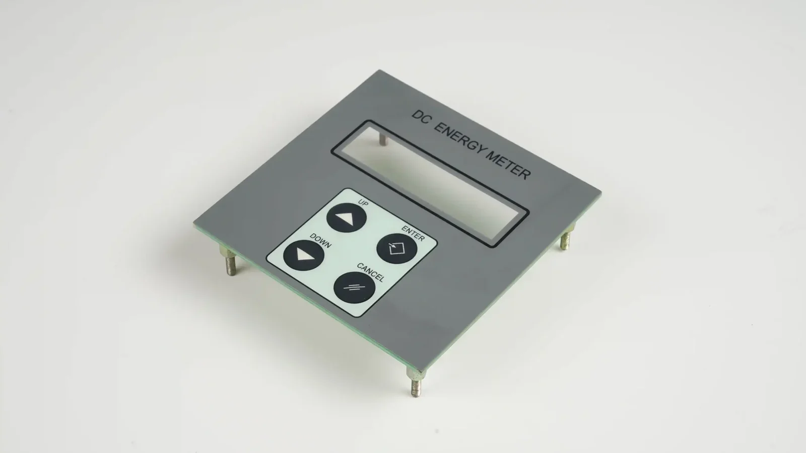
A graphic overlay prototype is ready for approval only when it answers named questions about artwork, color, opacity, windows, embossing, converted geometry, adhesive, liner, fit, and documentation. One attractive loose sample cannot answer all of them. Separate visual, functional, assembly, and production-intent evidence, then record which file and specimen state supports each decision. The approval output should be a controlled release package with closed items, accepted deviations, unresolved risks, and recheck triggers, not an email that says the sample looks good.
For an OEM panel project, JASPER’s custom graphic overlays page is the commercial route for reviewing a printed, cut, formed, and adhesive-backed construction. The quotation must still confirm the actual film, print process, colors, windows, embosses, adhesive, liner, tooling, inspection, and production scope. This checklist does not adopt the current product page’s numerical limits, named materials, compliance claims, or timing statements as a universal specification.
Start With an Open-Item Register, Not a Sample Request
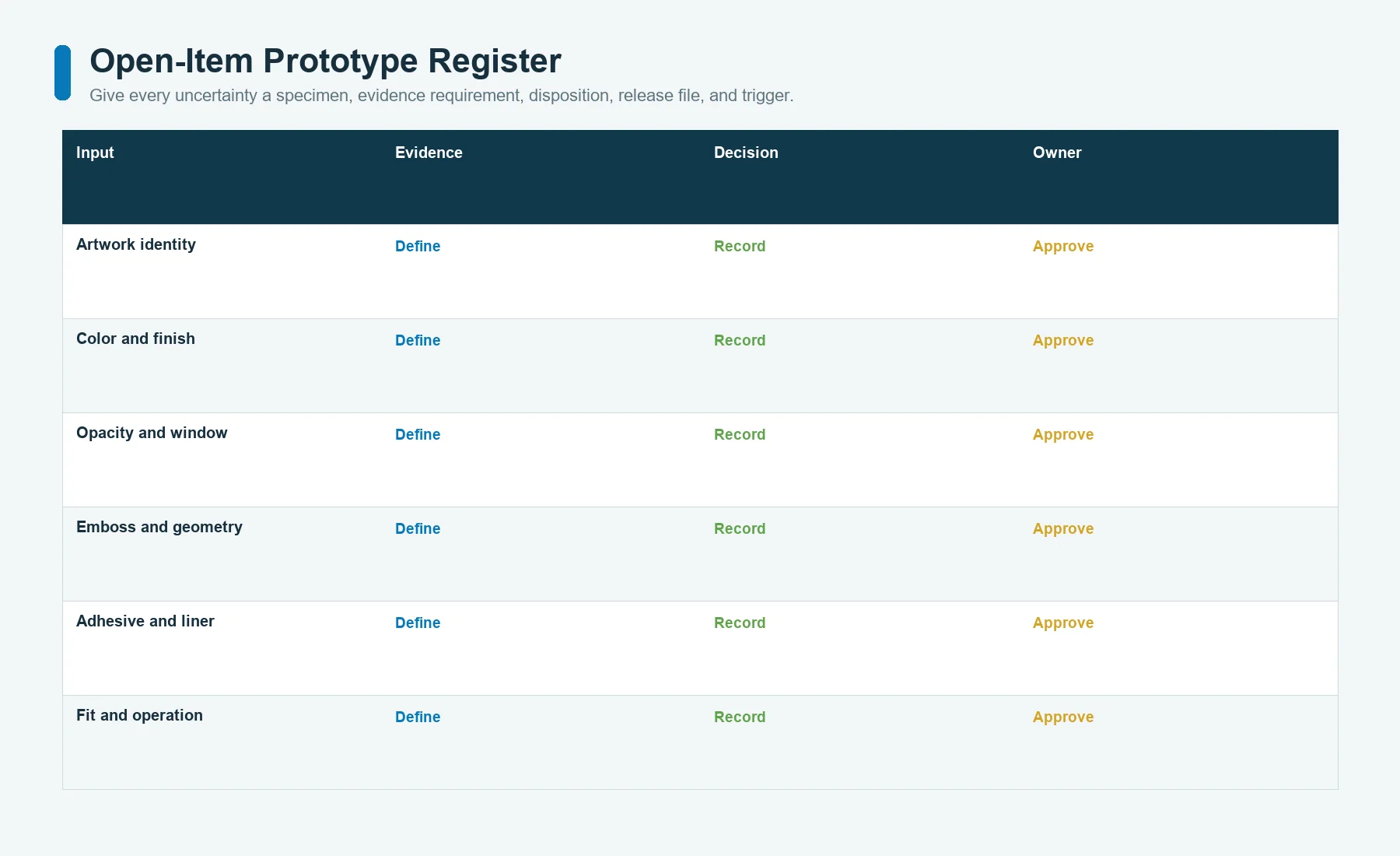
The most useful prototype request begins with uncertainty. List what is not yet proven, identify the specimen needed to answer it, and define how the result will change the release.
Use this record:
Open Item | Prototype Type | Reference | Specimen State | Evidence | Disposition | Release File | Recheck Trigger
An open item might be:
- whether the printed gray matches the adjacent molded enclosure;
- whether an inactive indicator remains hidden;
- whether a display window stays readable after bonding;
- whether an emboss aligns with the switch below it;
- whether the adhesive wets a textured production surface;
- whether the die-cut part sits inside a recess without lifting;
- whether the liner lets an operator place the overlay without stretching it.
The prototype type and specimen state matter. A color drawdown can answer a color-selection question but not fit. A loose die-cut overlay can answer outline and window registration but not adhesive edge behavior. A bonded and powered assembly can answer installed optical questions that a flat proof cannot.
The register prevents one sample from being approved for questions it was never built to answer.
Separate Visual, Functional, Assembly, and Production-Intent Evidence
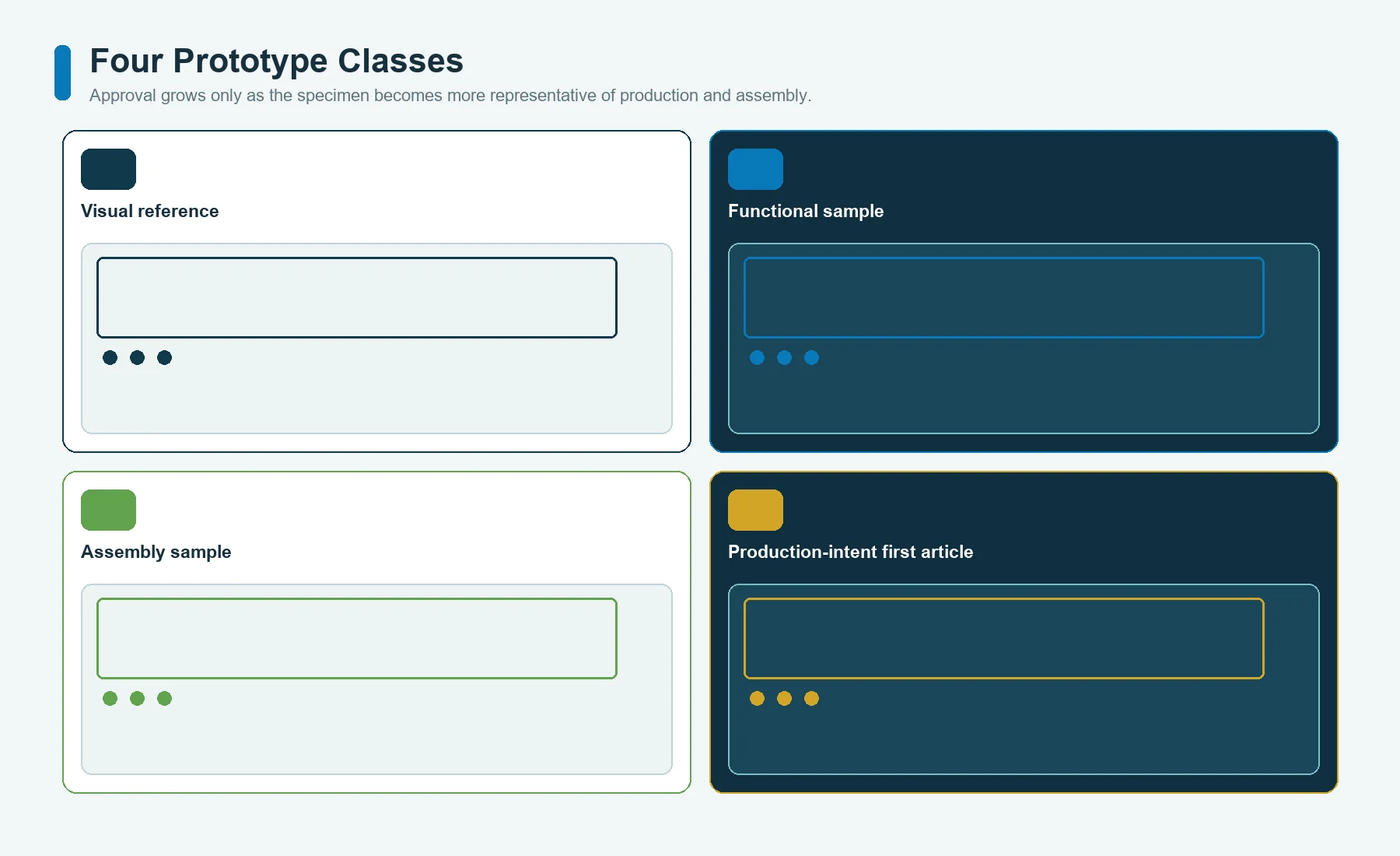
Four prototype labels help keep evidence honest:
| Prototype class | Main questions | What it cannot approve by itself |
|---|---|---|
| Visual reference | color, texture, gloss, print order, opacity, clear or tinted appearance | production die cut, adhesive bond, emboss function, assembly fit |
| Functional sample | emboss response, window operation, indicator visibility, repeated flexing or pressing where required | final appearance if materials or process differ |
| Assembly sample | outline, holes, recess fit, substrate bond, liner, placement, installed window and edge condition | repeat production if tooling, process, or released files are not final |
| Production-intent first article | released materials, artwork, tooling, converting, assembly state, inspection, records | future lots after an uncontrolled change |
These classes may use separate specimens or one combined sample. The important point is not the label. It is the question and the production relevance.
A fast visual sample made by one printing route may be valuable for layout review even when production will use another route. Record that limitation. A hand-cut fit sample may answer whether the outline works, but it cannot approve the final cutting tool or registration. A production-intent first article should use the released process and controlled files, yet it still needs measured and visual evidence rather than status by name alone.
Freeze the Reference Pack Before Making a Part
Prototype evidence is weak when the reference files continue changing while samples are being evaluated.
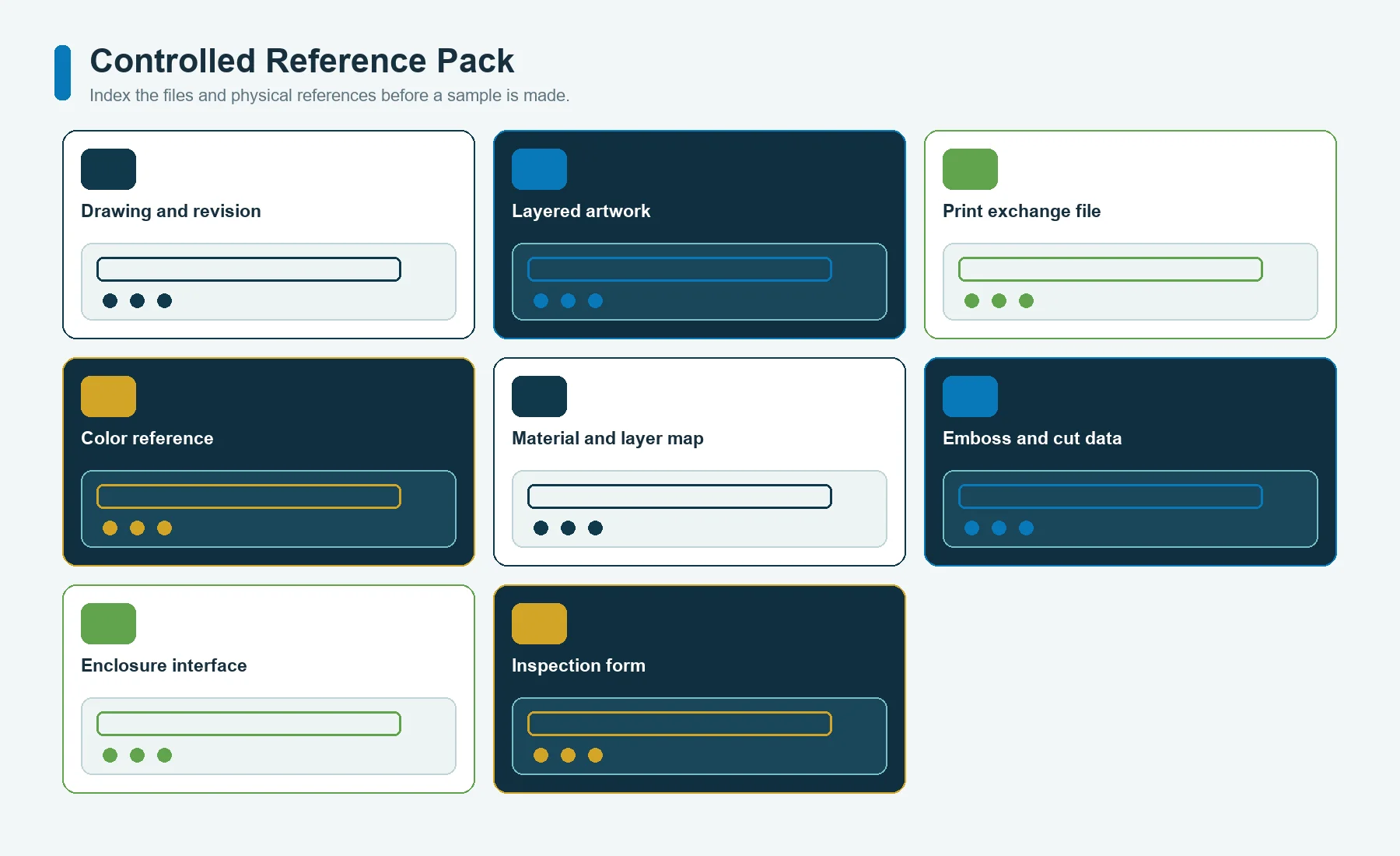
Create one indexed pack containing:
- dimensioned overlay drawing and revision;
- layered source artwork;
- print-ready exchange file;
- font, linked-image, and variable-data policy where relevant;
- color references and viewing condition;
- film and visible-finish identity;
- print-side and layer-order map;
- opacity, blocker, translucent, and clear-zone map;
- emboss or formed-feature drawing;
- cut line, hole, window, and adhesive geometry;
- enclosure and display interface drawing;
- substrate material and surface condition;
- adhesive and liner proposal;
- prototype question register;
- inspection and disposition form.
ISO 15930-7 defines PDF/X-4 for complete exchange of printing data using PDF. That kind of controlled exchange can reduce missing or ambiguous print data, but it does not replace the layered source, mechanical drawing, physical color reference, or final assembly evidence.
The prototype record should state exactly which revision was built. If artwork changes after printing, the existing sample can remain useful for material, finish, or fit questions, but it no longer approves the changed graphics.
Prove Artwork Meaning Before Evaluating Color
Artwork proofing starts with information identity, not color preference.
Check:
- part number and revision;
- language and legend text;
- symbol meaning and orientation;
- product and customer marks;
- warning hierarchy;
- variable and fixed data;
- print side and viewing side;
- mirror state for reverse printing;
- knockout and overprint intent;
- white, blocker, translucent, and clear separations;
- emboss, key, window, cut, and adhesive reference layers;
- hidden construction layers excluded from visible output.
The proof should show what the operator sees and how the printer builds it. Those are different views. A composite PDF may look correct while a white backing layer, blocker, or transparent zone is missing from the production separations.
Use the graphic overlay printing capability as a planning route for artwork, opacity, window, color, and registration questions. The page does not prove a particular print method, ink, cure, tolerance, or inspection result for the prototype.
Do not begin subjective color approval until the text, symbols, layers, orientation, and geometry are correct. Otherwise a later artwork correction invalidates time spent approving the wrong visual object.
Approve Color Under a Named Viewing Condition
Color approval needs a physical reference, specimen state, light condition, background, and observer rule.
ISO 3664 defines viewing conditions for reflective and transmissive media used in graphic technology. ISO 13655 defines spectral measurement and colorimetric computation for graphic-arts images. Those standards provide formal context; they do not select a JASPER color tolerance or substitute for a customer-approved reference.
Record:
- color identity and approved reference;
- instrument or visual method;
- illuminant and viewing environment where applicable;
- loose, adhesive-laminated, bonded, or illuminated specimen state;
- film surface and texture;
- white backing or substrate color;
- adjacent enclosure color;
- viewing angle and gloss sensitivity;
- allowed lot or location variation;
- disposition when instrument and visual results disagree.
A monitor screenshot is not a physical color standard. A loose reverse-printed film can also look different after white, blocker, adhesive, and enclosure layers are added. If color must match a molded or painted part, inspect the overlay beside a representative production surface.
The approval record should distinguish selected target, measured result, and visually accepted result. Those entries are not interchangeable.
Inspect Opacity and Layer Order in Every Required State
Opacity is a stack property. A printed color can match in ordinary room light yet allow an underlying rib, adhesive edge, display border, LED, or unused icon to show through.
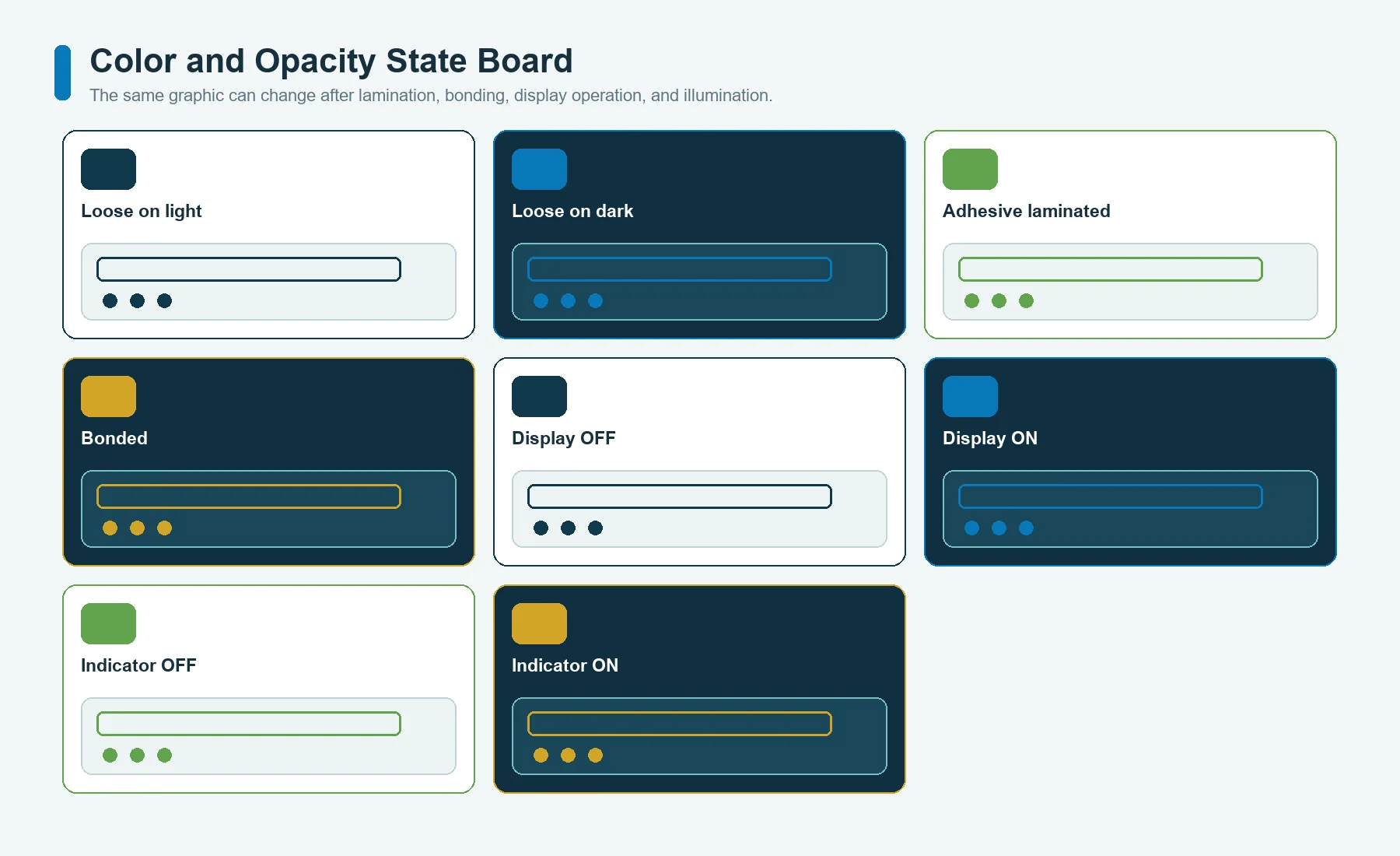
Define the required states:
- loose over a controlled light and dark background;
- adhesive laminated;
- bonded to the actual or representative enclosure;
- display off;
- display on;
- indicator off;
- indicator on;
- backlight at approved conditions;
- bright ambient and low ambient where relevant.
For each zone, identify whether it must:
- remain opaque;
- transmit an image;
- pass diffuse light;
- reveal a colored indicator;
- hide an inactive feature;
- match the surrounding printed field;
- remain free of adhesive or blocker.
Inspect layer order, white support, opaque blocker, translucent print, adhesive opening, and enclosure background as one stack. A heavier white or blocker may improve concealment but can change color, thickness, cure, flexibility, and print registration. The prototype should close those tradeoffs before the production artwork is frozen.
Do not use opaque as a pass condition without naming the state and the defect being controlled.
Treat Every Window as a Separate Optical Zone
A display or indicator window needs its own approval record. The visible result can be affected by film finish, coating, print edge, tint, adhesive, air gap, display bezel, surface contamination, scratches, particles, and local stress.
ASTM D1003 covers haze and luminous transmittance measurements for transparent plastics. Those terms can help define a window requirement, but the standard does not choose a universal value or prove display readability in the finished equipment.
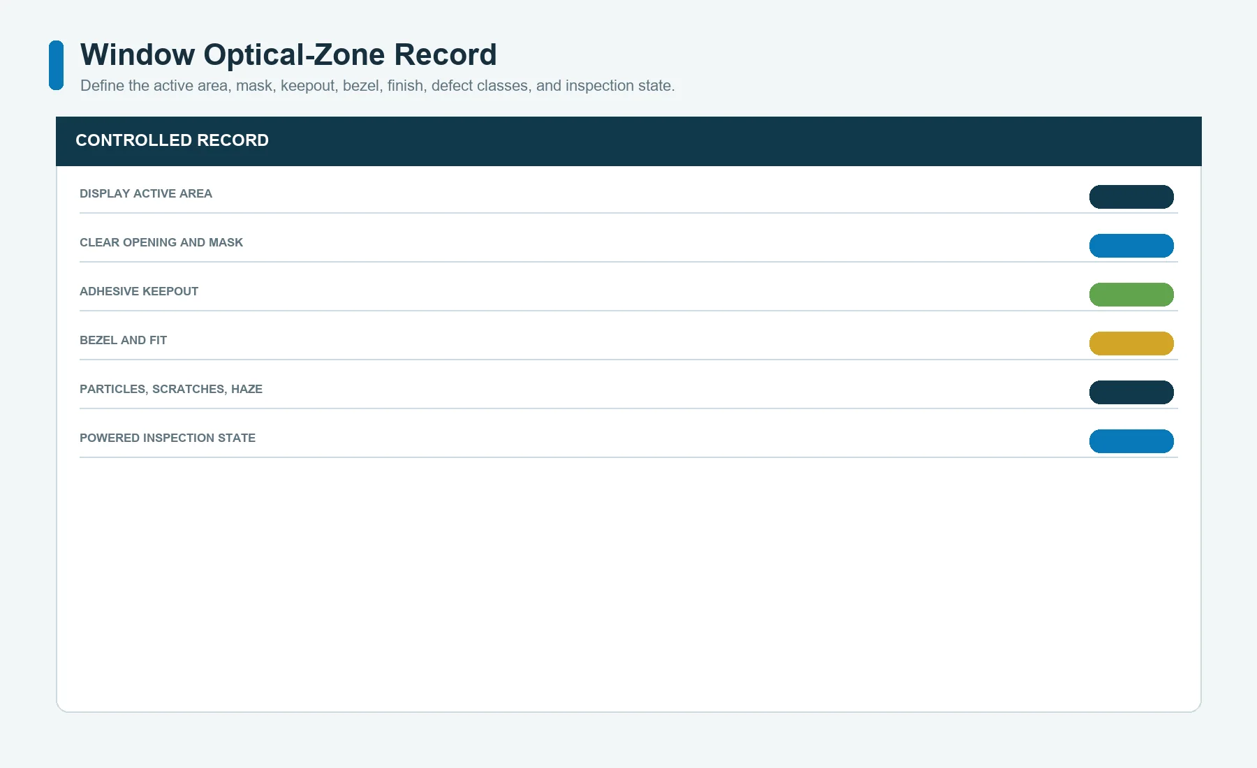
Record for each window:
- active display or indicator area;
- full clear or tinted opening;
- border and mask geometry;
- adhesive and blocker keepouts;
- loose and bonded appearance;
- display-off and display-on condition;
- allowed particle, scratch, haze, distortion, and edge defects;
- inspection background and lighting;
- protective mask and packing requirement;
- fit to bezel, gasket, or cover.
The graphic overlay display-window case study is useful for connecting window clarity, opacity, adhesive layout, cleaning exposure, and housing information. It remains a planning example, not proof that a proposed construction passed a named optical or chemical test.
Approve the real powered display state when readability matters. A clear-looking loose window can still show Newton-like fringes, trapped particles, adhesive intrusion, stress marks, or bezel mismatch after assembly.
Keep Emboss Approval Narrow and Measurable
An embossed feature can be visually attractive and still be wrong for the switch, enclosure, or operator.
The prototype record should identify:
- feature purpose;
- emboss type and orientation;
- location relative to the print and cut datums;
- plan and section geometry;
- flat-state and formed-state drawing relationship;
- switch, dome, spacer, or support below it;
- surrounding flat land;
- window, adhesive, and cut interactions;
- visible print distortion;
- functional press or flex observation;
- measured profile and location evidence;
- accepted deviation and correction scope.
Commercial overlay films differ by polymer, surface, hardcoat, print treatment, window behavior and emboss suitability. Evaluate these properties for the selected film; a material portfolio does not establish universal emboss geometry, process settings or manufacturing capability.
The detailed coordinate-chain and formed-profile method belongs in the planned embossed-overlay article. Until that route is live, keep the visible link absent and record the dependency in the deployment plan.
Prove Die-Cut Geometry Against Product Datums
The cut overlay must fit the product, not just the overlay drawing.
Inspect:
- outside profile;
- internal cutouts;
- holes, slots, notches, and vents;
- window and display relationships;
- key and emboss relationships;
- recess and bezel clearance;
- exposed edge condition;
- corner and narrow-feature behavior;
- protective-mask and liner edges;
- adhesive cutouts and split lines;
- orientation and assembly cues.
ISO 5459 provides formal context for datums and datum systems. ISO 1101 provides formal context for geometrical tolerancing of form, orientation, location, and run-out. The overlay drawing still has to choose the functional datum and inspection method.
A sample can pass its own outside dimensions and fail the enclosure because the overlay and housing were measured from different origins. Use the same product datums to relate visible graphics, windows, embosses, holes, and cut edges to the equipment.
Inspect the loose part and a correctly placed assembly. Placement error, recess clearance, adhesive stretch, and enclosure variation can create a different result from flat dimensional inspection.
Bond the Prototype to the Actual Substrate
Adhesive approval requires the actual overlay construction, substrate, surface condition, geometry, installation method, and exposure plan.
The substrate record should identify:
- resin, alloy, coating, paint, powder coat, anodizing, or other surface;
- supplier and grade when controlled;
- texture, curvature, flatness, recess, and edge;
- molding or processing additives that may affect the surface;
- cleaning, drying, storage, and handling;
- application temperature and environment where project specific;
- pressure application and dwell method;
- removability or service requirement;
- expected fluids, cleaners, heat, moisture, UV, or movement;
- changes that reopen review.
Adhesive bonding depends on the substrate and its surface condition. Select cleaning, priming, abrasion and any special-surface treatment from the instructions for the actual adhesive and substrate, then verify them in the assembly trial. No single preparation method applies to every overlay.
Use representative production parts whenever possible. A clean laboratory plaque can compare adhesive candidates, but it does not reproduce a textured recess, molded curvature, edge stress, contamination, or operator placement.
Separate Adhesive Selection From Installation Method
A suitable adhesive can fail through poor placement, contamination, trapped stress, incomplete pressure, or an uncontrolled liner. A marginal adhesive can also appear acceptable during a short room-temperature fit check.
Evaluate two evidence groups:
| Evidence group | Questions |
|---|---|
| Construction fit | Does the adhesive bond to the printed overlay back, avoid windows and moving features, convert cleanly, and remain compatible with the stack? |
| Installation fit | Can the operator position, tack, press, and finish the overlay on the actual enclosure without stretch, bubbles, wrinkles, trapped contamination, or edge lift? |
ASTM D3330/D3330M provides test methods for peel adhesion of pressure-sensitive tape. Peel data can support comparison under declared conditions, but it is not the same as overlay service life, edge resistance, curved-surface retention, or complete assembly validation.
Record the specimen width, substrate, preparation, application, dwell, pull condition, and failure mode if a peel method is used. A number without those conditions is difficult to compare.
The prototype approval should state whether adhesive selection is final, conditional on later exposure testing, or only a fit candidate.
Use the Liner and Peel Features in the Assembly Trial
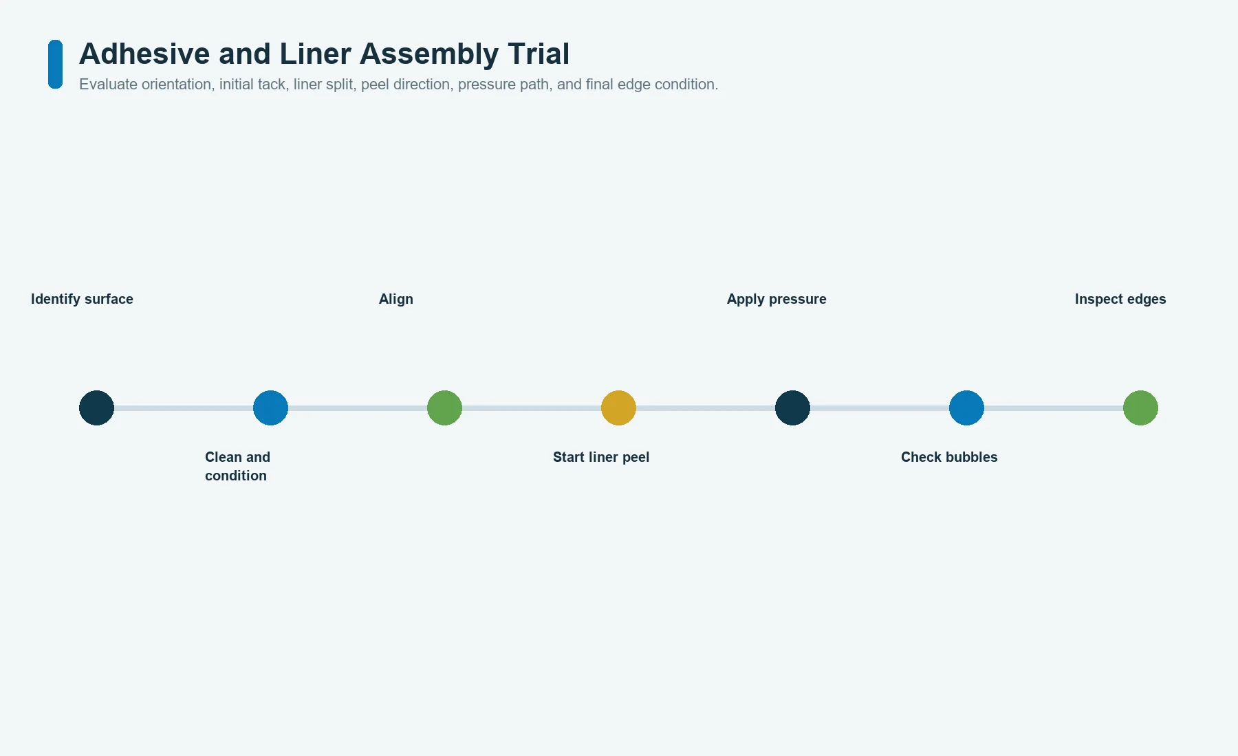
The release part includes the liner system. A full liner, split liner, peel tab, kiss-cut section, or exposed start edge can change placement quality and handling damage.
During the trial, observe:
- how the operator identifies orientation;
- where the first adhesive contact occurs;
- whether the part can be aligned before full tack;
- whether the liner forces an awkward peel direction;
- whether the overlay bends, stretches, or contacts itself;
- whether windows or glossy areas collect fingerprints;
- whether a peel tab damages print, film, or adhesive;
- whether the liner leaves debris or adhesive transfer;
- whether a fixture is needed;
- whether rework is allowed and how it is recognized.
Use the intended gloves, fixture, cleaning materials, and access conditions. An engineer applying one sample on an open bench may not reproduce the production operator’s reach, visibility, cycle, or enclosure constraints.
The assembly trial should produce a work-instruction redline and an inspection point, not only a bonded sample.
Inspect the Overlay Loose, Bonded, and Operating
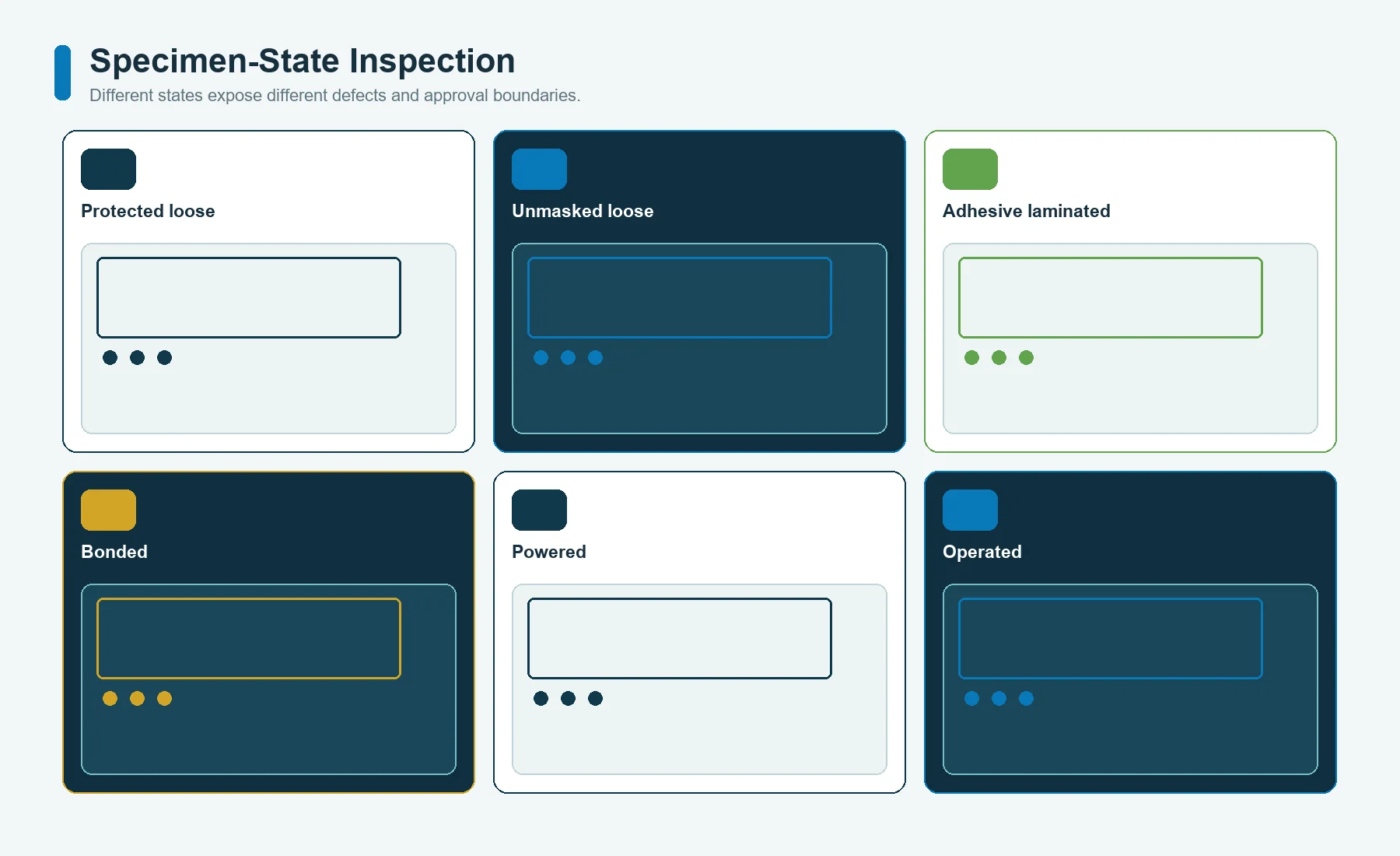
Different defects become visible in different states.
| State | Questions that state can answer |
|---|---|
| Loose, protected | print completeness, gross color, film finish, cut quality, surface defects |
| Loose, protection removed | gloss, texture, window scratches, particles, handling sensitivity |
| Adhesive laminated | adhesive outline, liner, local distortion, contamination, backing influence |
| Bonded to enclosure | fit, edge, recess, bubbles, wrinkles, color against substrate, bond contact |
| Powered assembly | display and indicator windows, opacity, light leakage, dead-front behavior |
| Operated assembly | emboss alignment, key accessibility, flexing, tactile or interface interaction |
Do not merge these into one visual inspection line. Name the state, reference, lighting, viewing distance or instrument method where relevant, and defect class.
If the panel is inspected immediately after bonding and again after a defined conditioning period, keep those results separate. The article does not prescribe a universal dwell time; the approved adhesive and project requirements must define it.
Record Defects by Information Class, Not “Looks Good”
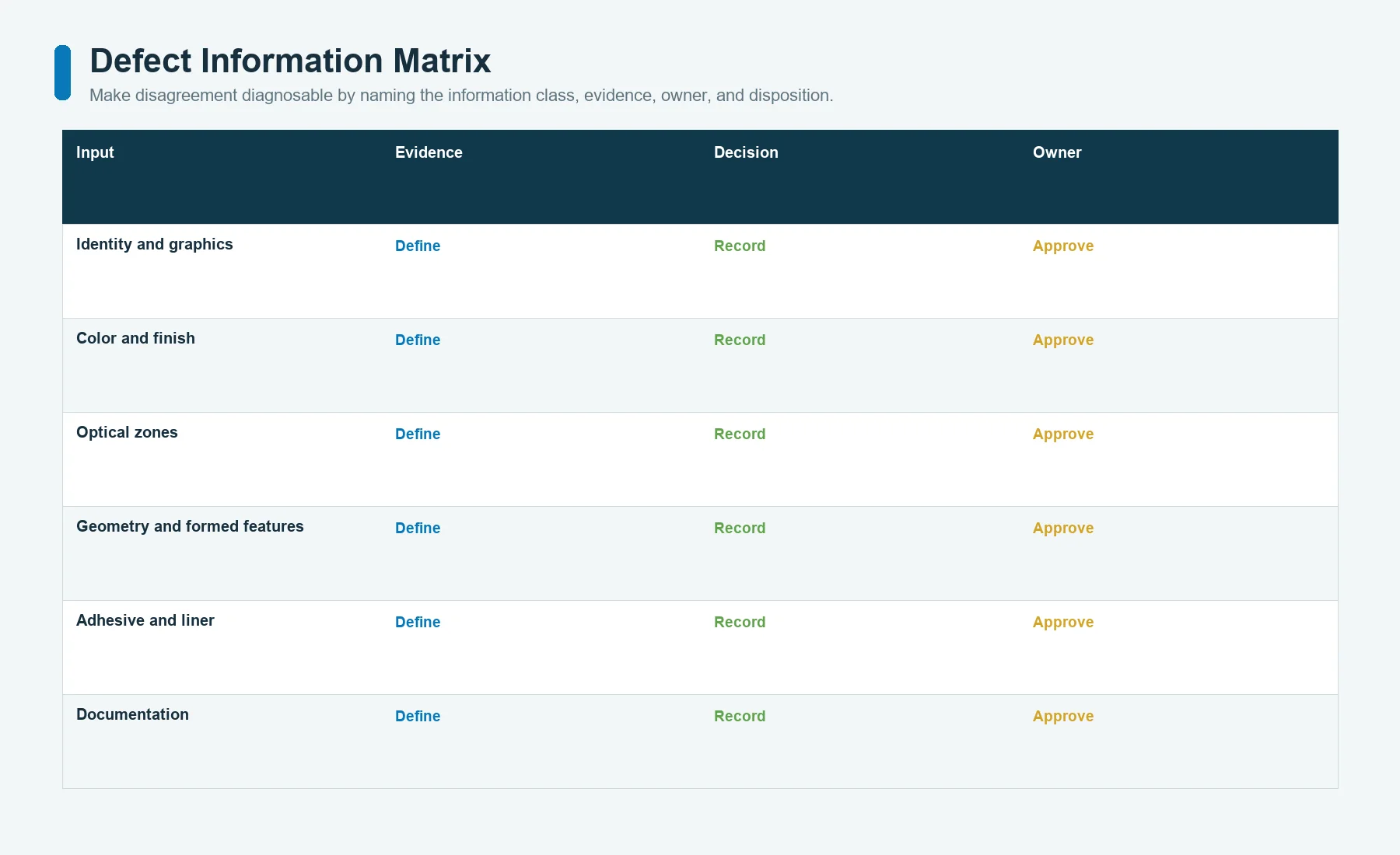
The prototype report should make disagreement diagnosable.
| Information class | Example observations | Release owner |
|---|---|---|
| Identity | part, revision, language, mark, orientation | document and product owner |
| Graphics | missing, shifted, broken, wrong layer, wrong symbol | artwork and print owner |
| Color and finish | target mismatch, gloss shift, texture mismatch, enclosure mismatch | industrial design and quality |
| Optical zones | haze, particle, scratch, leakage, blocker edge, tint, display masking | optical and product owner |
| Geometry | outside profile, hole, window, recess, datum, fit | mechanical and supplier quality |
| Formed features | location, profile, print distortion, function | mechanical and interface owner |
| Adhesive | coverage, keepout, contamination, lift, bubble, failure mode | materials and assembly owner |
| Liner and assembly | peel, orientation, handling, placement, fixture | manufacturing engineering |
| Documentation | missing reference, unrecorded deviation, wrong revision | document control |
Use photographs with scale and orientation, measured records where a dimension applies, and a clear disposition:
- accept;
- accept with recorded deviation;
- rework prototype;
- revise file and rebuild;
- defer to a named later test;
- reject the construction.
Looks good does not identify what was inspected, what reference was used, or what can change without another sample.
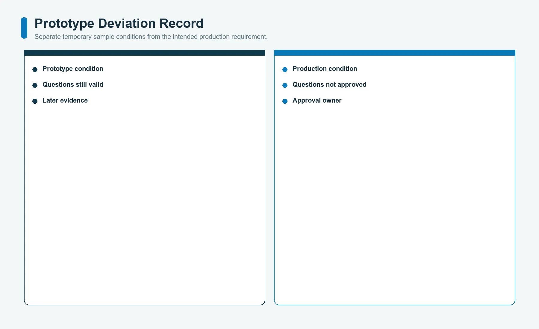
Distinguish a Prototype Deviation From a Production Requirement
Prototype processes often differ from production in tooling, print setup, cutting method, quantity, handling, or material availability. Those differences must be declared before approval.
For each difference, record:
- prototype condition;
- intended production condition;
- reason for the difference;
- questions the prototype can still answer;
- questions it cannot answer;
- evidence required from the production-intent first article;
- approval owner.
Examples include hand cutting instead of final tooling, temporary material for layout only, digital color sample before production print, adhesive applied by a non-production method, or a manually formed emboss.
A prototype deviation should never disappear inside the approved sample. If the buyer signs the sample without the deviation record, the supplier may treat a temporary feature as the visual target or assume it was accepted as production representative.
Conversely, do not require an early concept sample to meet every production criterion when its declared purpose is only artwork orientation or fit. The open-item register keeps the approval proportional to the sample’s purpose.
Build a Golden Reference Without Freezing a Defect
A retained approved sample can help align future visual judgment, but it is not a complete specification.
Pair the sample with:
- unique sample ID;
- part and revision;
- build date and process state;
- material and print record;
- measured color or dimension records where used;
- signed deviations;
- photographs of critical zones;
- storage and handling rule;
- replacement or revalidation rule;
- links to controlled drawing and artwork.
The retained sample should not override an updated drawing or hide a known defect. Mark accepted deviations directly in the release record. If color, gloss, window clarity, or adhesive appearance can change during storage, identify which measured or digital records remain authoritative.
NIST’s measurement-process guidance separates repeatability, reproducibility, calibration, gauge studies, and process control. That distinction matters when a golden sample is used across observers, instruments, sites, and time. A sample can align judgment, but the organization still needs a controlled measurement and disposition process.
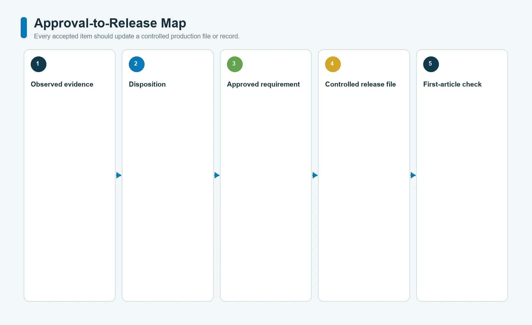
Convert Every Approval Into a Release File
The prototype closes only when evidence changes a controlled file.
| Approved item | Release file that should change or close |
|---|---|
| text, symbols, orientation | master artwork and artwork proof |
| color and finish | color standard, measurement record, visual approval |
| opacity and layer order | separation map and print construction |
| window | optical-zone map, cut/adhesive keepout, inspection criteria |
| emboss | formed-feature drawing, tool record, inspection plan |
| die cut and fit | dimensioned drawing, datum map, cutting-tool revision |
| adhesive | bill of materials, adhesive pattern, substrate and installation record |
| liner | liner drawing and work instruction |
| prototype deviation | deviation and disposition record |
| final sample | first-article report and retained-sample identity |
Keep file ownership explicit. A PDF proof may own visible layout while the dimensioned drawing owns geometry. The material record owns film and adhesive identity. The inspection plan owns method and acceptance. The prototype report owns what was observed.
Conflicting files must be resolved before production. A print operator should not have to decide whether the artwork, an email screenshot, a mechanical drawing, or the physical sample is authoritative.
Define Recheck Triggers Before Production
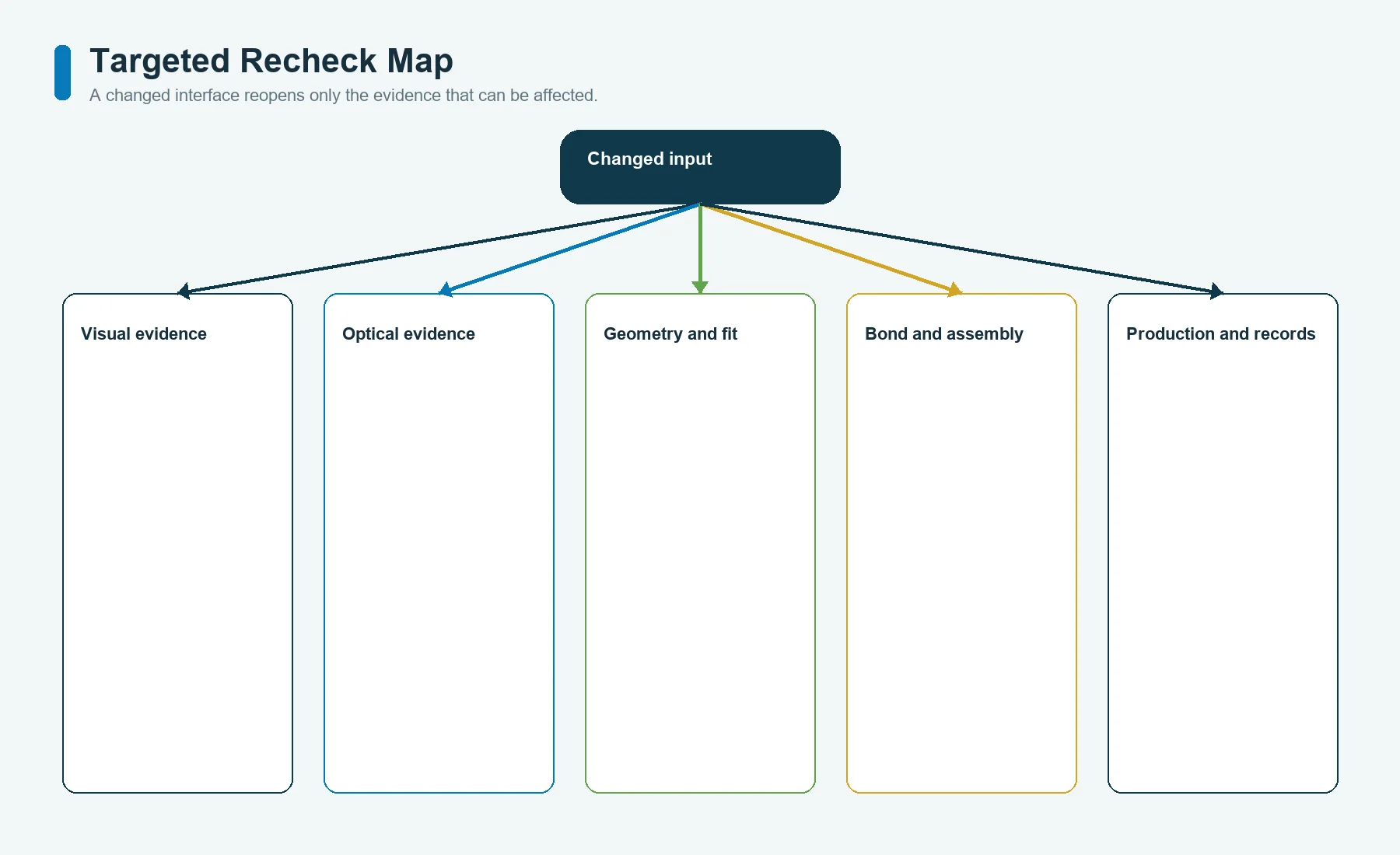
Approval should expire for the affected evidence when a relevant input changes.
Recheck examples:
- film supplier, grade, gauge, surface, coating, or print treatment;
- ink, white, blocker, translucent layer, cure, or print sequence;
- color reference or adjacent enclosure color;
- display, indicator, diffuser, air gap, or light source;
- adhesive, primer, substrate, coating, texture, cleaning, or installation;
- emboss geometry, tool, forming route, or support;
- cutting tool, datum, outline, hole, window, or recess;
- liner, peel tab, assembly fixture, or work instruction;
- supplier, site, process, inspection method, or software used for output;
- artwork, language, logo, variable data, or regulatory mark.
ASTM D1204 provides a method for examining linear dimensional change in nonrigid thermoplastic film at elevated temperature. It can support one material-screening question, but it does not replace print, form, cut, bond, and assembly revalidation after a construction change.
The recheck scope should follow the changed interface. An adhesive change may reopen bond, liner, assembly, and optical appearance without requiring a new text proof. A display change may reopen window and opacity evidence without changing the cut outline. Name the affected evidence rather than rebuilding everything by habit.
Stop When the Prototype Cannot Answer the Question
Do not approve the prototype when:
- the built revision cannot be identified;
- the reference pack contains conflicting files;
- the sample uses an undeclared non-production process;
- color has no physical or measured reference;
- window approval omits the installed and powered state;
- opacity is judged over the wrong background;
- emboss and cut features use unrelated datums;
- the substrate or surface preparation is not production representative;
- adhesive evaluation has no failure mode or assembly trial;
- the liner and placement method were not tested;
- deviations are accepted only in email or conversation;
- the retained sample is expected to override controlled files;
- a material, process, or product change has no recheck rule.
The correct decision may be to approve only a subset of questions. For example, approve text and layout while holding color, adhesive, and fit open. Partial approval is more useful than a broad approval that has no evidence boundary.
Prepare a Graphic Overlay Prototype Package
Use JASPER’s prototyping capability to review the planned evidence after the project files and questions are assembled. Use the graphic overlay materials resource to identify film, surface, adhesive, window, and exposure inputs that must be confirmed before the prototype construction is fixed.
Submit through the JASPER request-for-quote form:
- part number, revision, application, and approval owners;
- layered artwork and print-ready proof;
- dimensioned drawing and product datums;
- enclosure, display, indicator, switch, and recess interfaces;
- physical color and finish references;
- opacity, window, and illumination states;
- formed-feature and cut requirements;
- film, print, adhesive, substrate, and liner constraints;
- cleaning, environment, handling, and service conditions;
- visual, functional, assembly, and production-intent questions;
- allowed prototype deviations;
- inspection, disposition, retained-sample, and recheck requirements;
- prototype and annual quantities.
The quality and testing framework can connect each open item to the specimen, method, result, acceptance, and retained record. The first output should be the open-item register and reference-pack index. That gives the prototype a defined job before artwork, tooling, material, or schedule decisions are treated as approved.
Frequently Asked Questions
Can one attractive graphic overlay sample approve production?
No. A loose visual sample cannot by itself approve adhesive bonding, enclosure fit, powered windows, emboss function, liner handling, production tooling, or repeatability.
What prototype classes should be separated?
Separate visual references, functional samples, assembly samples, and production-intent first articles, then state what each specimen can and cannot approve.
Can color be approved from a monitor or screenshot?
No. Use a named physical or measured reference, viewing condition, specimen state, background, surface finish, and disposition rule.
Why should adhesive be checked on the actual enclosure surface?
Bonding depends on the complete overlay, substrate material, coating, texture, contamination, curvature, installation method, and exposure, not the adhesive name alone.
What belongs in a graphic overlay prototype release package?
Include controlled artwork, drawing, color reference, layer map, material and adhesive record, emboss and cut data, work instruction, deviations, first-article evidence, and retained-sample identity.
What changes should trigger a prototype recheck?
Recheck the affected evidence after changes to film, print stack, color, display, adhesive, substrate, emboss, cutting tool, liner, artwork, inspection method, or assembly process.
Ready to Start Your Project?
Tell us about your membrane switch, keypad, or graphic overlay requirements. Our engineering team will review your specifications and provide a detailed quote.