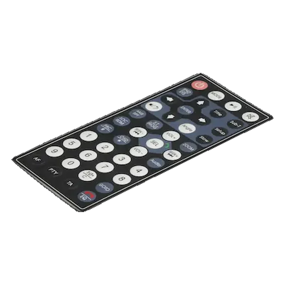
Graphic overlay printing opacity is the percentage of light a printed ink layer blocks on a polyester or polycarbonate facesheet, governing color fidelity, dead-front legend hiding, and the suppression of backlight bleed. It is measured by TAPPI T 425, ISO 2471, and ink pass-count, not by eye.
For an OEM graphic designer or HMI engineer writing the print spec inside an RFQ, opacity is the single variable that decides whether a control panel reads cleanly under shop-floor sodium lamps or looks washed-out on the first production batch. The 7-line section below defines opacity in the overlay context, walks through three concrete ways inadequate opacity fails in the field, and ties each failure mode back to a measurable spec a buyer can write into a print drawing.
- 1. Opacity in Graphic Overlay Printing — A Working Definition
- 2. Why Opacity Decides Whether the Overlay Passes Incoming Inspection
- Failure mode 1 — Color shift from substrate show-through
- Failure mode 2 — Backlight bleed on dead-front graphics
- Failure mode 3 — Inconsistent LCD window framing
- 3. Printing Methods and Substrate Variants — Where Opacity Comes From
- 4. How Opacity Is Measured and Specified
- Standards an RFQ can name
- Pass-count guidance for the two dominant ink layers
- Optical density vs. percent opacity — quick conversion
- 5. Where Opacity Specs Matter Most
- 7. Related Reading
1. Opacity in Graphic Overlay Printing — A Working Definition
In a graphic overlay, opacity is the fraction of incident light that fails to pass through a printed ink layer, expressed either as a percentage on the 0–100 % TAPPI T 425 / ISO 2471 scale or as optical density (OD) on a log10 scale. A reading of 99 % opacity equals roughly OD 2.0; 99.9 % equals OD 3.0. The same number can be printed in ink, but only the substrate-plus-ink stack determines the final value a viewer actually perceives.
Overlay printing differs from poster or label printing in one structural detail: the artwork is almost always second-surface. Ink is deposited on the underside of a clear PET (polyester) or polycarbonate film — Macdermid Autotype Autotex XE, Bayer Makrofol DE 1-1, and Tekra Marnot are three named substrates used industry-wide — then the film is laminated face-up onto the membrane-switch circuit. The user sees the print through the film. Every ink pass must therefore deliver opacity from the backside, against a substrate that itself is 70–250 µm thick and slightly hazed by the hardcoat.
That single fact — second-surface viewing — drives every opacity decision that follows.
2. Why Opacity Decides Whether the Overlay Passes Incoming Inspection
Opacity matters in graphic overlay printing because three distinct failure modes appear on first-article inspection when the ink stack is too thin, and each maps to a separate physical cause. Designers who treat opacity as “a printing detail the vendor handles” tend to discover the gap only after the first 500-piece pilot run reads inconsistently under the customer’s lighting.
Failure mode 1 — Color shift from substrate show-through
A single-pass red printed on clear PET reads orange or pink, not red. The clear substrate plus any ambient light bouncing off the bonded circuit below shifts the perceived hue. The fix is an opaque-white blocker printed behind every colored area — typically 2 to 3 passes of a high-opacity white ink such as Marabu MaraSwitch SR-070 or Pröll NORIPAN HF 089. Without the blocker, Pantone Solid Coated color targets cannot be hit on PMS C; ΔE values run 4–8 against the standard, and the overlay fails any color spec tighter than ΔE ≤ 3.
Failure mode 2 — Backlight bleed on dead-front graphics
A dead-front overlay hides an icon (warning triangle, on/off legend) until the LED behind it turns on. The icon appears only when illuminated. This requires the surrounding area to be near-fully opaque to LED light — typically OD ≥ 2.5, or 99.7 % opacity, on the blocked region. A 2-pass black layer over a 1-pass dark grey base typically lands around OD 1.5; the icon then ghosts visibly even with the LED off. The industry rule of thumb is 4 passes of opaque black for a true dead-front, with the icon area masked from one of the passes.
Failure mode 3 — Inconsistent LCD window framing
Where the overlay frames a clear LCD viewing window, the surrounding ink stack must block side-lit reflections that would otherwise bleed into the LCD area and reduce contrast. Insufficient opacity around the window produces a halo under fluorescent lighting and a visible ink-shadow under sunlight. Spec: opaque black ≥ OD 3.0 (99.9 %), measured at the edge of the window cutout, before lamination.
In all three modes, the engineer writing the RFQ cannot specify “make it look good.” The specifiable parameters are pass count, optical density, and the named ink/substrate combination — covered in §4.
3. Printing Methods and Substrate Variants — Where Opacity Comes From
The overlay industry uses two dominant print processes and two surface orientations. Each combination yields a different attainable opacity ceiling per pass.
| Variant | Distinguishing feature | Typical opacity per pass | Where it is used |
|---|---|---|---|
| Screen printing, second-surface | Thick ink film, 8–15 µm wet | High — opaque white reaches 96–99 % at 2–3 passes | Membrane switches, industrial HMI |
| Screen printing, first-surface | Same ink film, applied on the user-facing side | Same, but exposed to abrasion | Rarely used alone; combined with overprint varnish |
| Digital UV (inkjet), second-surface | Thin ink film, 3–6 µm wet | Lower — opaque white needs 4–6 passes for equivalent OD | Short runs, photo-realistic graphics |
| Digital UV, first-surface | Same | Same, with hardcoat overprint required | Prototypes, low-volume HMI |
| Dead-front layer (special) | Stacked opaque black over opaque grey | OD 2.5–3.0 at 3–4 passes | Backlit icons, LCD framing |
A few non-obvious consequences affect the specification. First, digital UV cannot match screen-print opacity at the same pass count; teams that switch from screen to digital to cut tooling cost often discover the ink stack now needs twice the passes to hit the same OD — eroding the cost saving. Second, the second-surface orientation almost always wins on durability because the ink is shielded from abrasion by the substrate itself; the trade-off is that every color the designer specifies must sit on top of an opaque-white blocker, doubling the layer count for any printed area.
For the specific case of second-surface printing on a membrane switch, the canonical stack from substrate down to circuit is: hardcoated PET (front) → primer → spot colors → opaque white blocker (×2 or ×3) → optional dead-front black (×3 or ×4) → dielectric / adhesive → top circuit. Designers should reference this stack explicitly in their artwork files, calling out which areas need the blocker and which need the dead-front.
4. How Opacity Is Measured and Specified
Opacity in graphic overlay printing is specified against four named standards plus an ink-pass-count guideline that ties the standard back to a printable instruction.
Standards an RFQ can name
| Standard | What it covers | How to use it in an overlay print spec |
|---|---|---|
| TAPPI T 425 | Opacity of paper, 0–100 % diffuse-reflectance scale | Substitute ink-on-clear-film for paper; require ≥ 98 % for blocker layers |
| ISO 2471 | International equivalent of TAPPI T 425 | Cite when the customer’s QA system is ISO-aligned |
| ASTM D2805 | Hiding power of paint at complete obliteration | Apply to opaque-white inks; specify “complete hiding per ASTM D2805” |
| ASTM D589 | Opacity of pigmented printing inks | Direct match for screen-print and digital-UV overlay inks |
| Pantone Solid Coated (PMS C) | Spot-color reference + dot-gain and opacity guidance | Use the ΔE ≤ 3 target on the printed overlay measured with a spectrophotometer |
| ASTM D7027 / ISO 2813 | Surface gloss measurement | Pair with opacity in QA: gloss change > 5 GU at 60° indicates ink-film thickness drift |
Pass-count guidance for the two dominant ink layers
| Layer | Target opacity | Screen-print passes | Digital-UV passes | Named ink reference |
|---|---|---|---|---|
| Opaque white blocker behind any color | ≥ 98 % (OD ≥ 1.7) | 2–3 | 4–5 | Marabu MaraSwitch SR-070, Pröll NORIPAN HF 089 |
| Dead-front opaque black | ≥ 99.7 % (OD ≥ 2.5) | 3–4 | 5–6 | Marabu MaraSwitch SR-960, Pröll NORIPAN HF Black |
| LCD-window frame black | ≥ 99.9 % (OD ≥ 3.0) | 4 | 6 | Same as above, plus edge mask |
| Single spot color (Pantone) over white blocker | ΔE ≤ 3 vs PMS C | 1–2 | 2–3 | Any vendor with Pantone formulation |
The pass-count is not a substitute for the standard — it is a predictor a designer can write into the spec (“opaque white per ASTM D2805, achieved by ≥ 2 screen-print passes of Marabu MaraSwitch SR-070 or equivalent”). On incoming inspection, the QA team verifies with a transmission densitometer (X-Rite 361T or equivalent) against the OD target, not by counting passes. The pass count is the manufacturing instruction; the OD is the acceptance criterion.
Optical density vs. percent opacity — quick conversion
| Percent opacity | Optical density (OD) | Common overlay layer |
|---|---|---|
| 90 % | 1.0 | Light spot color over blocker |
| 99 % | 2.0 | Standard opaque-white blocker |
| 99.7 % | 2.5 | Dead-front black |
| 99.9 % | 3.0 | LCD-window frame black |
| 99.99 % | 4.0 | Specialty optical mask (rare) |
5. Where Opacity Specs Matter Most
Four overlay use cases drive almost every opacity-related rejection in incoming inspection. The print spec language for each is different.
Medical infusion-pump and patient-monitor faceplates demand dead-front legends so that warning icons appear only when a fault triggers them; spec OD ≥ 2.5 on the dead-front area and reference IEC 60601-1 third-edition labeling rules for the icon contrast ratio.
Industrial HMI panels on CNC and PLC enclosures sit under fluorescent or LED ceiling lighting that throws a 45° glare across the overlay; spec ≥ 99 % blocker behind every color and a matte hardcoat (Autotex XE or equivalent) with 60° gloss between 8 and 15 GU.
Backlit appliance keypads (induction cooktops, espresso machines) frequently use a 3-pass black plus 1-pass white legend visible in the LED-on state; specify dead-front OD ≥ 2.5 with the legend masked out of one black pass.
Outdoor instrument overlays (irrigation controllers, EV charging stations) require both opacity and UV stability; the spec adds an ASTM G154 cycle test on top of the opacity target, and the ink choice typically locks to Marabu MaraSwitch SR-FU or Pröll NORIPAN HF UV-stable variants.
6. Frequently Asked Questions
Why does ink opacity matter for graphic overlay printing?
Opacity determines whether the printed legend reads its specified Pantone color, whether dead-front icons stay hidden until illuminated, and whether LCD windows display without halo. Without an opaque-white blocker behind each color, the clear PET substrate lets light through and shifts hue by ΔE 4–8 against PMS C targets.
How many ink passes are needed for a fully opaque black overlay?
Three to four screen-print passes of Marabu MaraSwitch SR-960 or Pröll NORIPAN HF Black reach OD ≥ 2.5 (99.7 % opacity) — the dead-front threshold. Digital UV needs five to six passes for the same OD because the ink film is thinner (3–6 µm wet vs. 8–15 µm for screen). LCD-frame black needs one additional pass to reach OD 3.0.
What is the opacity standard for second-surface overlay printing?
There is no single ISO standard for “second-surface overlay opacity,” but the industry references four: TAPPI T 425 and ISO 2471 for percent opacity, ASTM D2805 for hiding power at complete obliteration, and ASTM D589 for pigmented-ink opacity. RFQs typically write “opacity per ASTM D2805, OD ≥ 2.5 on dead-front, ≥ 1.7 on blocker layers.”
How is opacity measured on a finished overlay?
A transmission densitometer (X-Rite 361T, Techkon SpectroDens, or equivalent) reads optical density through the printed area. For percent-opacity readings, an opacimeter following the TAPPI T 425 method is used with the printed film backed alternately by black and white standards.
What is a dead-front overlay, and what opacity does it require?
A dead-front overlay hides a backlit icon until the LED behind it activates. The surrounding ink stack must block ambient and LED light by OD ≥ 2.5 (99.7 % opacity). This is typically achieved by 3–4 passes of opaque black, with the icon area masked from one of the passes so it lights up cleanly.
Can digital UV printing match the opacity of screen printing?
Yes, at higher pass count. Digital UV deposits 3–6 µm wet per pass versus 8–15 µm for screen, so reaching the same OD requires roughly twice the passes. For a 99.7 % dead-front black, screen takes 3–4 passes; digital UV takes 5–6. Cycle time and ink cost rise correspondingly.
Does the substrate affect perceived opacity?
Yes. A hardcoated PET (Autotex XE, 178 µm) reads slightly more opaque than a clear polycarbonate (Makrofol DE 1-1, 175 µm) at the same ink layer, because the hardcoat scatters incident light by ~3 %. On critical color matching, request a printed sample on the production substrate before approving the artwork.
What pass count is typical for opaque white on clear film?
Two to three screen-print passes of Marabu MaraSwitch SR-070 or Pröll NORIPAN HF 089 reach 98 % opacity (OD ~1.7), the standard blocker spec behind colored areas. Digital UV requires four to five passes for the same value. A single pass typically reads 70–80 % — visibly translucent.
7. Related Reading
For a designer about to send artwork into production, the opacity spec lives alongside material selection (PET vs. polycarbonate), color management (Pantone Solid Coated workflow), and durability testing (ASTM G154 UV cycling). Most overlay manufacturers — including [graphic overlay](/graphic-overlay/) suppliers serving the membrane-switch market — accept artwork with explicit pass-count and OD callouts and reject artwork that specifies only Pantone numbers.
This explainer was published by JASPER Electronics, a Shenzhen-based graphic-overlay and membrane-switch manufacturer. The opacity standards, ink references, and pass-count guidance above apply industry-wide, not only to JASPER’s process.
Ready to Start Your Project?
Tell us about your membrane switch, keypad, or graphic overlay requirements. Our engineering team will review your specifications and provide a detailed quote.