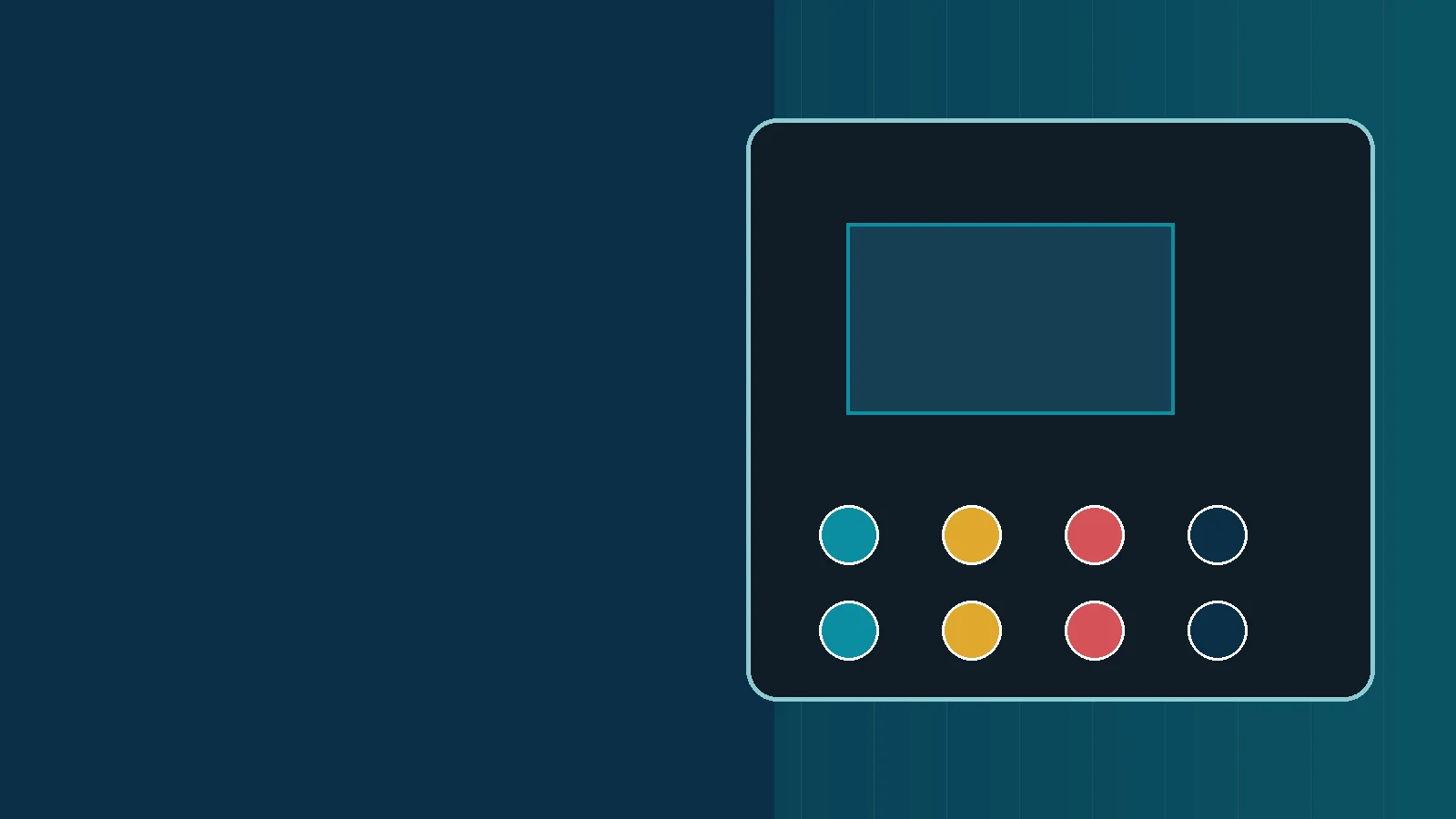
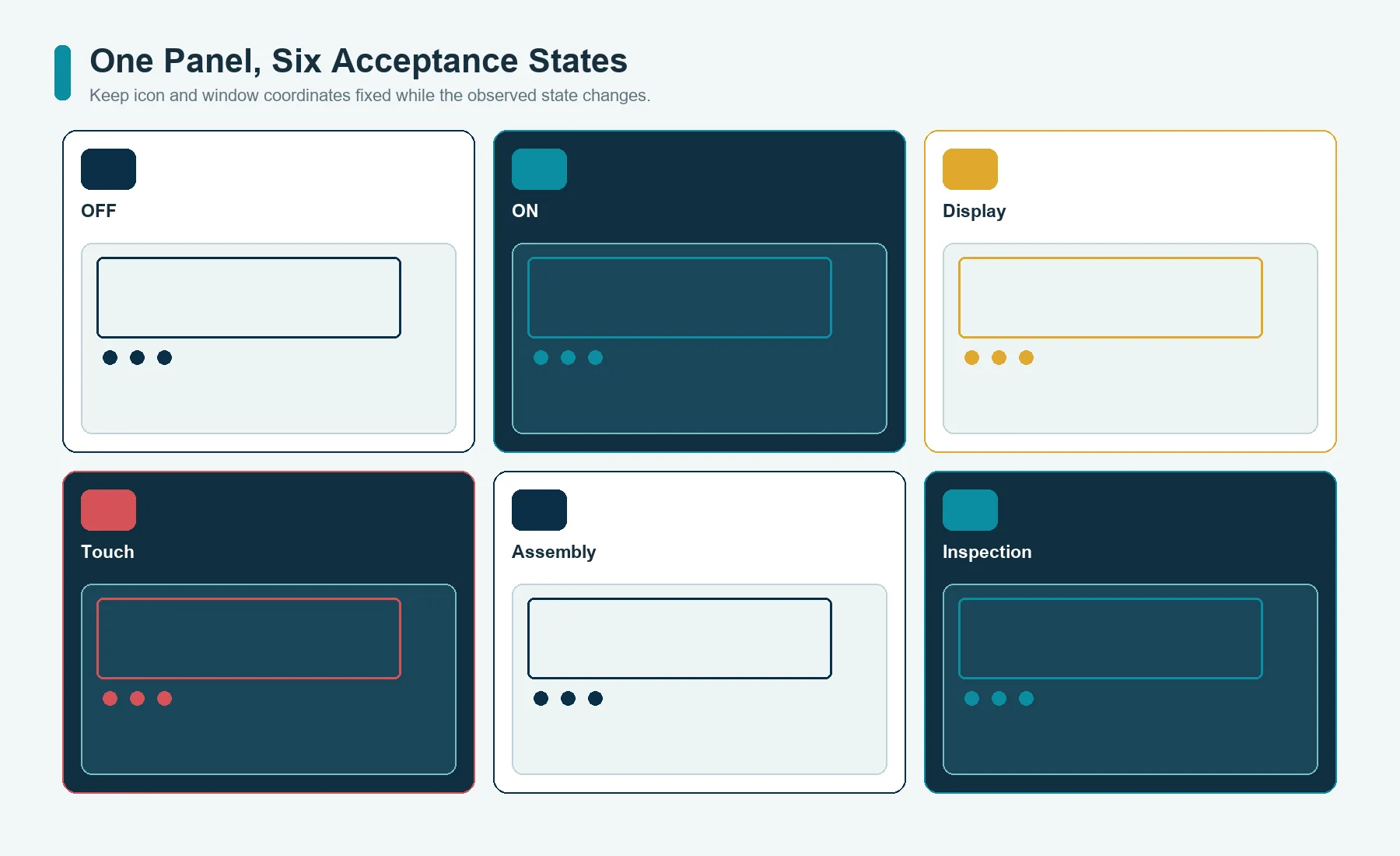
Dead-front glass panel printing succeeds only when the same panel is approved in every state in which the user and the electronics will see it. An icon that disappears on an unpowered sample may bloom, shift, or show pinholes when illuminated. A display window that looks clean against a white inspection card may tint blacks or clip pixels over the actual display. A touch key can align visually while the sensor, controller, adhesive, and printed stack produce weak or uneven response. The design authority must therefore connect OFF, ON, display, touch, assembly, and inspection states to one coordinate system.
JASPER’s glass nameplates and dead-front glass panels page is the commercial route for an OEM front surface that may combine hidden icons, printed masks, display windows, touch graphics, finished edges, and mounting features. This article defines the optical-zone and registration evidence that should accompany the artwork. It does not confirm a particular glass, ink, strengthening process, transmission target, touch performance, or manufacturing route.
One Panel Has Six Acceptance States
The phrase dead front usually describes one visual effect: selected graphics are difficult to see until light behind the panel is active. That effect is useful, but it is not a complete specification. The panel may also contain a display window, a touch sensor, status indicators, an opaque border, decorative color, holes, edge features, adhesive, and an enclosure aperture. Each of those elements changes what should be inspected.
Use six named states:
| State | What the observer should evaluate | Typical hidden failure |
|---|---|---|
| OFF | icon concealment, surface match, ambient reflections, print defects | icon ghost, color patch, pinhole, edge halo |
| ON | icon shape, brightness, uniformity, color, spacing | bloom, hot spot, dim edge, layer misregistration |
| Display | active image, black level, color, window edge, masked pixels | tint, haze, print intrusion, parallax, clipped image |
| Touch | key location, sensitivity distribution, false activation, recovery | weak key, adjacent-key coupling, drift, dead zone |
| Assembly | glass-to-LED, glass-to-display, glass-to-sensor, and glass-to-housing position | stack offset, tilted light source, unsupported glass |
| Inspection | fixture datum, lighting, camera or instrument, software, sample state | a measurement that cannot reproduce the product condition |
Do not approve one state and infer the others. A powered icon photo does not prove OFF-state concealment. A glass-only color reading does not approve the display view. A controller demonstration on a bench does not approve the installed touch stack.
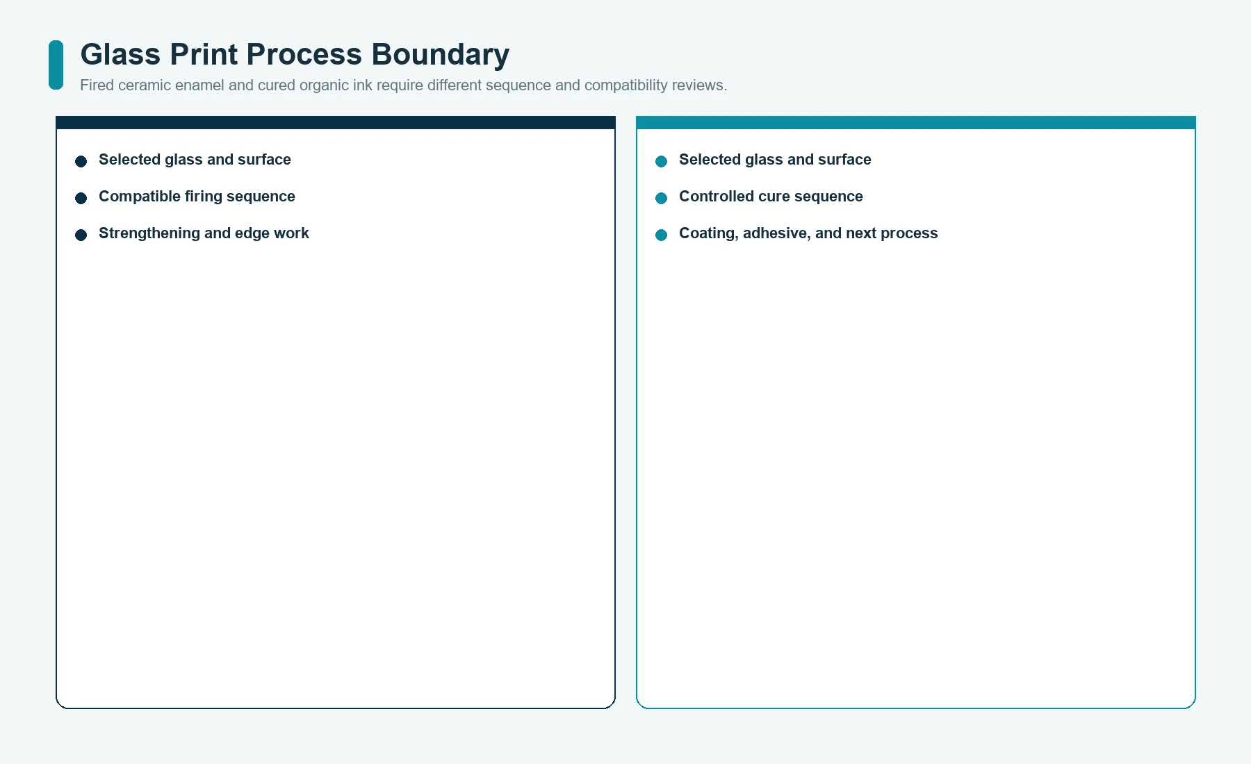
Ceramic or Organic Ink Is a Process Boundary
Ceramic enamel and organic ink are not interchangeable names for colored material on glass. They represent different process routes, thermal histories, layer behavior, and change controls.
Vibrantz describes automotive glass enamels as inorganic materials that are printed and fired so the enamel matures and bonds to the glass.[1] Nazdar’s 59000 series is an organic, solvent-based screen ink formulated for substrates that include glass.[2] Those supplier records support a narrow conclusion: both inorganic enamel and organic ink routes exist for printing glass, but they do not establish that either route fits a specific JASPER panel.
The selection record should identify:
- glass manufacturer, family, product form, and surface;
- whether the glass is annealed, heat treated, chemically strengthened, coated, or otherwise processed;
- whether printing occurs before or after the strengthening or coating step;
- exact ink or enamel family, color, medium, catalyst or hardener where applicable;
- print side, layer order, cure or firing route, and rework rule;
- compatibility with holes, edges, coatings, adhesive, optical bonding, and cleaning;
- required optical and adhesion evidence after the final process sequence.
Do not write ceramic ink merely because the part is glass. Do not write epoxy ink or organic ink without the selected grade and cure record. The process sequence must be agreed with the glass and ink suppliers before the drawing makes it a production requirement.
OFF State Means Controlled Leakage, Not Absolute Black
An OFF-state requirement should describe the viewing condition in which an inactive icon is judged. Invisible is not measurable by itself. The result changes with ambient illuminance, viewing angle, observer distance, panel color, surface reflection, icon size, neighboring graphics, and the light or bright structure behind the glass.
Define the condition:
- panel installed or placed over a representative dark backing;
- internal sources off and residual light controlled;
- stated ambient lighting geometry;
- stated observation direction and viewing cone;
- clean surface with the approved coating and handling condition;
- comparison against an approved master or an instrumental limit;
- separate rules for icon center, edge, pinholes, and print transitions.
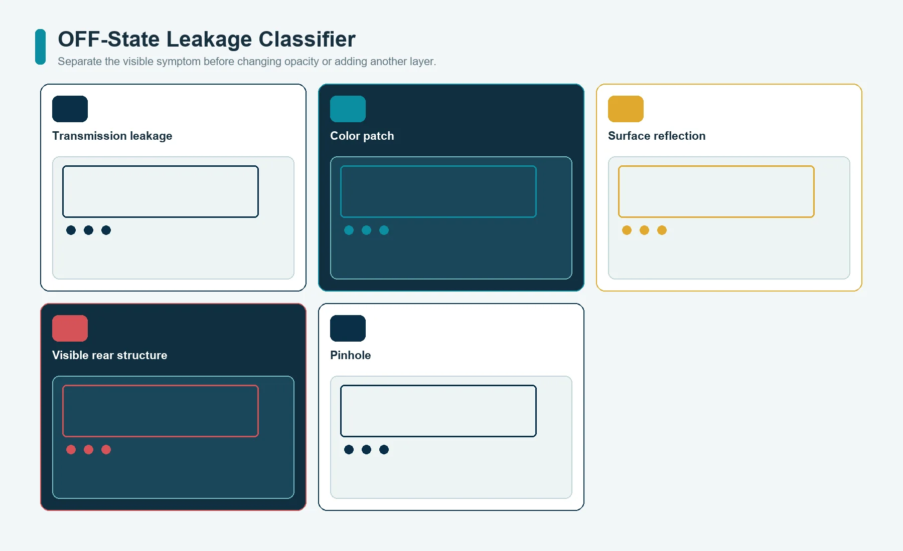
An icon can fail OFF state in more than one way. The opening may transmit too much ambient light from behind. The printed stack may have pinholes. A white support layer can create a visible patch even when transmission is low. A clear adhesive, sensor pattern, LED package, or display edge can outline the zone. Surface gloss may reveal the icon boundary at an oblique angle.
The OFF record should distinguish:
leakage through the zone | color mismatch around the zone | surface reflection | visible rear structure | print defect
Treating all five as opacity sends corrective work to the wrong layer.
ON State Belongs to the Complete Light Path
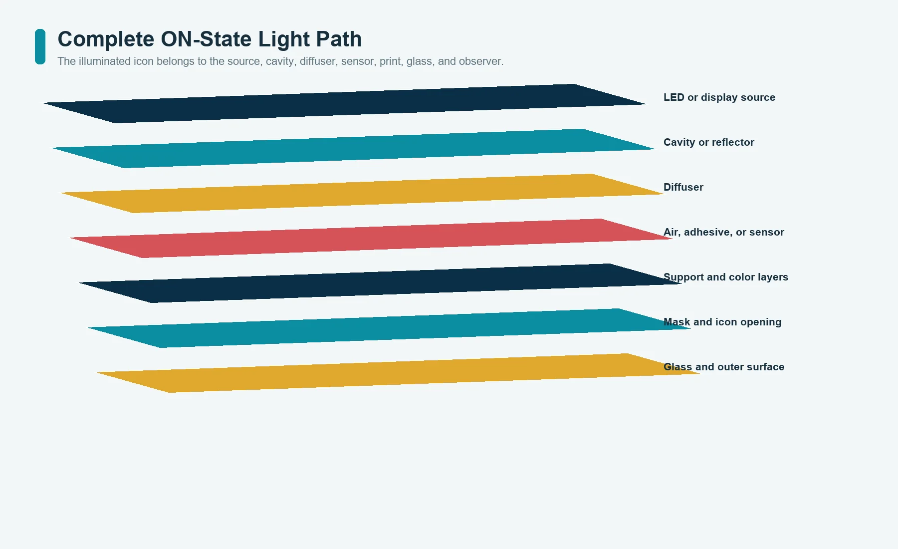
The printed opening does not create the illuminated result by itself. The result comes from the LED or display, optical cavity, reflector, diffuser, air gap or adhesive, sensor stack, glass, print layers, surface finish, and observer.
Draw the light path:
LED or display source
        |
reflector, cavity, light guide, or diffuser
        |
air, spacer, adhesive, or touch sensor
        |
glass-side printed support and color layers
        |
dead-front mask and icon opening
        |
glass and outer surface treatment
        |
operator viewing position
The ON-state inspection should identify the actual source part number or controlled optical equivalent, its position and orientation, drive condition, diffuser, housing color, and panel mounting. Replacing a diffuse source with a point source during inspection can create a hot spot that will not exist in the product. The reverse can hide a product hot spot.
Judge icon center, edge, internal fill, color, neighboring-zone leakage, and appearance across the required viewing cone. If brightness is measured, record the instrument, geometry, aperture, stabilization, background, and location. If a camera is used, lock exposure and image processing. Automatic phone-camera exposure is useful for communication but weak as acceptance evidence.
Display Windows Need Their Own Optical Contract
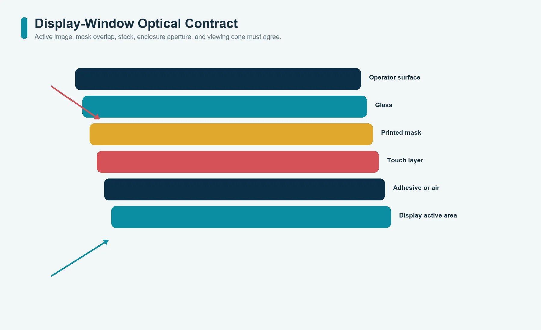
A display window is not simply a larger transparent opening. It carries displayed information, so the window must preserve the parts of the image that matter: black level, color relationship, fine text, segment edges, viewing cone, and border position.
The window contract should identify:
- display active area and mechanical outline;
- visible image area allowed by the enclosure and print mask;
- nominal glass, touch, adhesive, and display stack;
- mask overlap needed to hide the display edge without clipping valid pixels;
- clear, tinted, smoked, or selectively printed zones;
- acceptable contamination, haze, pinholes, streaks, and edge transition;
- required powered screens used during inspection;
- viewing angles and ambient conditions;
- any service or replacement alignment requirement.
ASTM C1649 covers instrumental determination of visible transmittance for glazing materials.[3] ASTM E1164 addresses obtaining spectrometric data for object-color evaluation, while ASTM E308 covers the calculation of color coordinates from spectral data.[4][5] These methods can help define a measurement chain. They do not choose the viewing condition, instrument setup, aperture, backing, acceptance limit, or display screen for an HMI.
Do not reduce a display-window approval to one transmittance value. Two windows can produce a similar aggregate transmission while differing in spectral tint, haze, local print intrusion, edge quality, or display readability.
Touch State Includes Ink, Adhesive, and Air
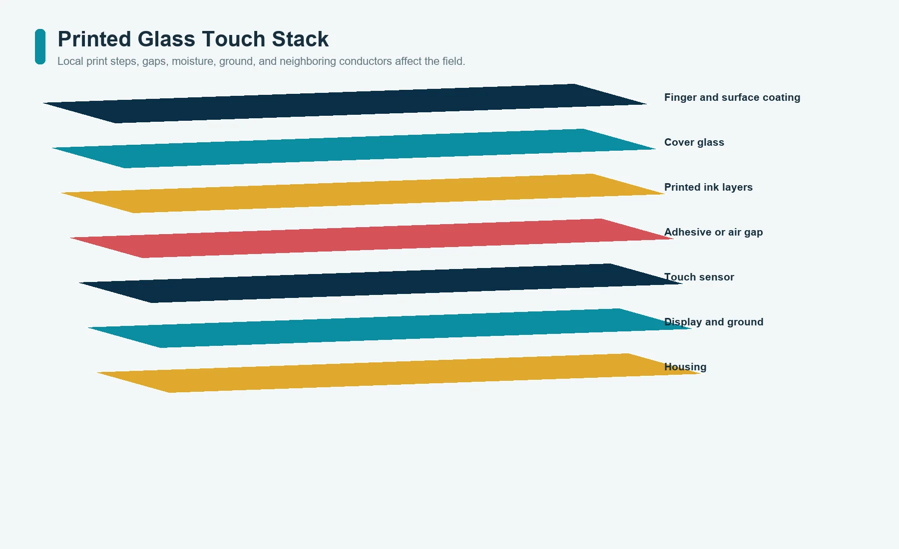
A capacitive touch key sees the complete dielectric and electrical environment above and around the electrode. The relevant stack can include cover glass, surface coating, printed layers, adhesive, sensor substrate, air pockets, enclosure ground, display, neighboring conductors, moisture, and the controller configuration.
Texas Instruments’ CapTIvate design guide treats overlay material, ink, adhesive, air gap, moisture, grounding, sensor geometry, and controller settings as connected design variables.[6] That supports a system boundary, not a universal glass thickness or sensitivity rule.
For every touch zone, record:
- electrode center, shape, neighboring electrodes, and routing reference;
- cover, print, adhesive, and sensor layer order;
- local air gaps, print steps, spacers, and unsupported regions;
- display, frame, fastener, shield, and ground proximity;
- controller and firmware identity;
- baseline, signal, noise, threshold, drift, and recovery evidence;
- dry finger, required glove, moisture, contamination, and cleaning states;
- false-touch and adjacent-key checks;
- installed housing, cable, power, and display operating condition.
The custom capacitive touch panel page is the commercial context for the complete cover, sensor, tail, controller, and enclosure interface. GO-03 stays narrower: it controls how the printed glass and optical zones share the touch coordinate system.
One Datum Chain Must Reach Every Hidden Component
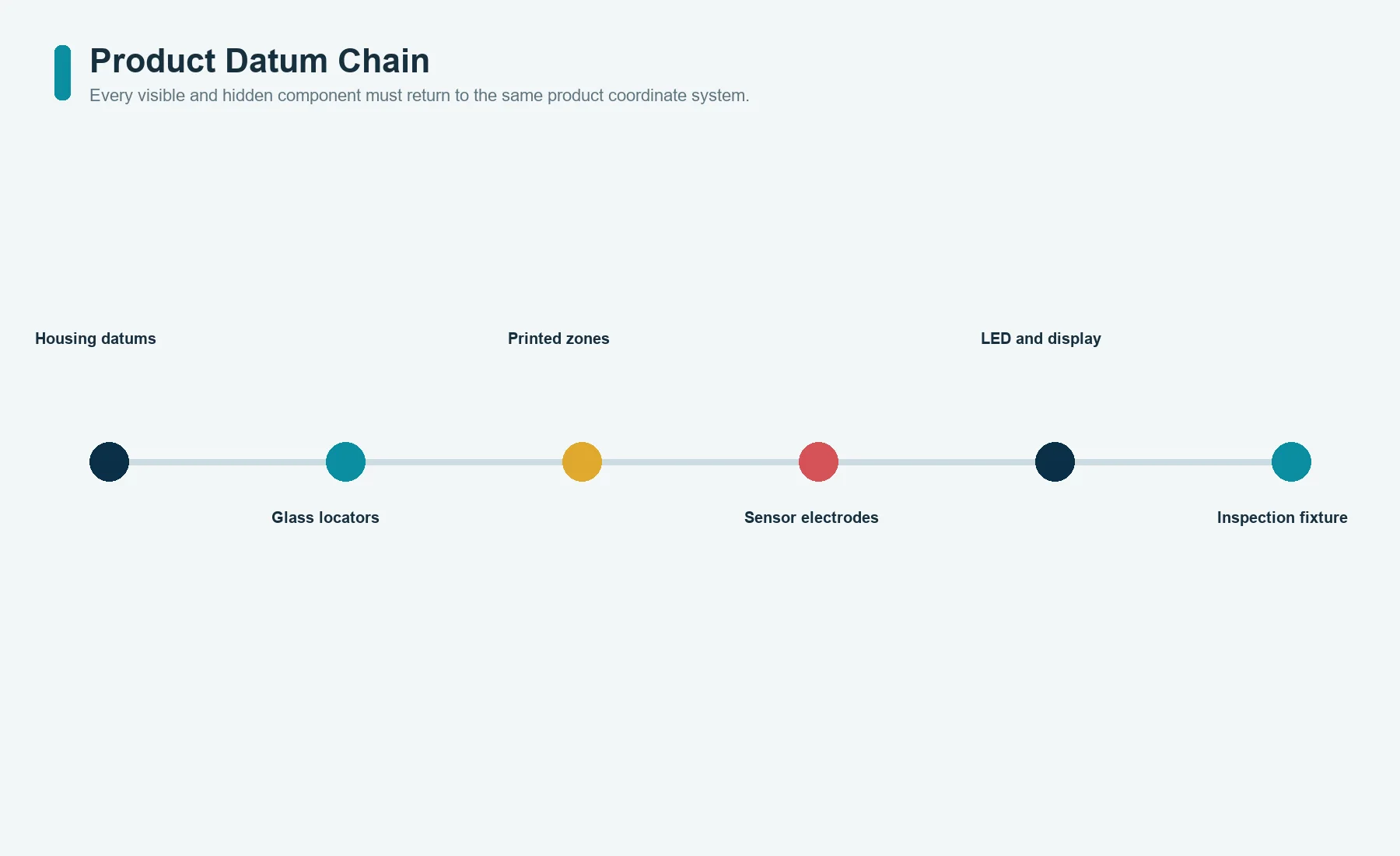
The operator sees icons on the glass, but the functional centers can live on several different parts. A printed key may need to align with a sensor electrode. An illuminated symbol may need to align with an LED and diffuser. A display window must align with the active image and enclosure aperture. The glass itself may locate from edges, holes, a nest, or adhesive features.
Use one explicit chain:
product housing datums
        |
glass locating features
        |
printed optical-zone coordinates
        |
sensor and electrode coordinates
        |
LED, diffuser, and display coordinates
        |
inspection-fixture coordinates
Nominal artwork can begin from an origin that has no direct physical role in the product. A screen frame mark, camera fiducial, glass corner, enclosure boss, display bracket, and sensor-tail datum can all use different coordinate frames. The release package must state how each frame returns to the product requirement.
The capacitive touch control panel case study provides related complete-stack planning context for overlay, sensor, grounding, display proximity, adhesive, enclosure, electronics, and inspection. It is not proof that an unnamed glass panel passed a touch or optical test.
Build an Optical-Zone Register Before Separating Artwork Layers
The zone register is the bridge between industrial design, electronics, glass printing, assembly, and inspection. Create it before the artwork is divided into print colors and production layers.
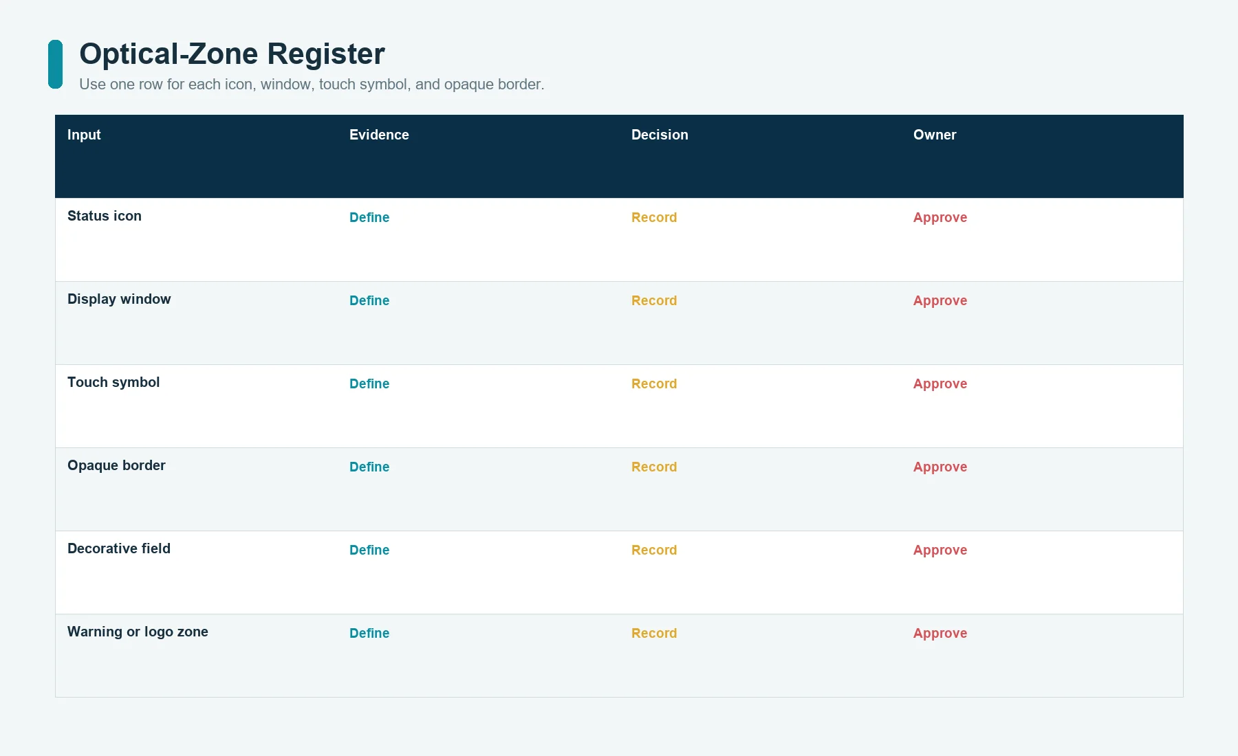
Use one row for every icon, display window, indicator, decorative field, touch key, logo, warning, and masked border:
| Optical Zone | OFF Requirement | ON Requirement | Datum | Measurement | Limit | Owner | Change Trigger |
|---|---|---|---|---|---|---|---|
| status icon | concealment and no edge ghost | uniform lit shape and color | product key center | approved fixture and image method | project-defined | HMI owner | LED, diffuser, ink, glass, gap |
| display window | surface and mask appearance | image readability and border | display active area | powered display screens plus optical method | project-defined | display owner | display, tint, print, bond |
| touch symbol | appearance and position | optional illumination result | sensor electrode center | visual plus touch validation | project-defined | touch owner | sensor, controller, cover stack |
| opaque border | uniform face and hidden structure | no unwanted edge leakage | housing aperture | visual and dimensional method | project-defined | mechanical owner | housing, adhesive, print |
Project-defined is not a final acceptance value. It is a stop sign that prevents the supplier from inventing one. Replace it before approval.
The register also prevents one owner from changing a zone without seeing another function. A wider black mask may hide a display edge but clip the image. A brighter LED may improve ON appearance while revealing pinholes or increasing adjacent leakage. A thicker support print may improve opacity while changing local touch response or print-step bonding.
Artwork Coordinates and Illuminated Coordinates Are Different Evidence
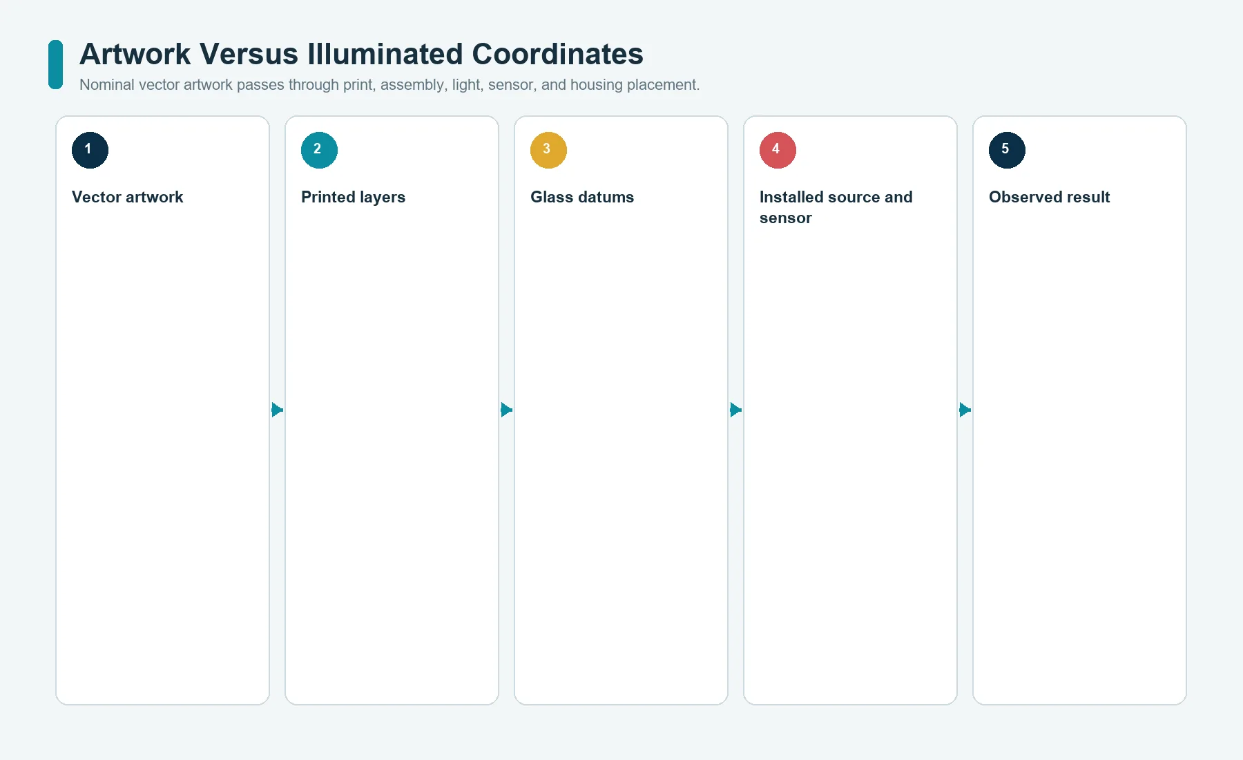
The artwork file describes nominal boundaries. The illuminated result can move because of screen registration, glass location, layer-to-layer placement, LED position, diffuser geometry, display position, sensor assembly, adhesive flow, housing fit, and viewing angle.
Separate at least these relationships:
- icon artwork to glass datum;
- color layer to blocker or support layer;
- icon opening to LED or light-guide center;
- display mask to display active area;
- touch symbol to electrode center;
- printed border to enclosure aperture;
- glass edge or hole to housing locator;
- finished assembly to inspection fixture.
A single print-to-print registration result does not prove the icon-to-LED relationship. An LED centered under the artwork on a bench does not prove it remains centered after the sensor and adhesive are assembled. A display mask can be dimensionally correct on glass while the bracket locates the display from another part.
The graphic overlay printing capability page remains the owner of broad color, opacity, window, artwork, and printing-process context. GO-03 uses printing only as one node in the installed optical coordinate chain.
Release the Print Stack Layer by Layer
The visible face may be generated by several printed layers. A dead-front icon can use a dark mask, color, translucent or white support, blocker, clear area, or other project-specific combination. The exact stack must come from supplier review and representative samples; it must not be inferred from a screenshot or a competitor sample.
For each layer, identify:
| Field | Required record |
|---|---|
| function | decorative color, concealment, support, transmission control, border, window, or process mark |
| print side | operator side or second surface |
| artwork authority | file, layer name, revision, scale, orientation |
| material identity | ink or enamel family, color, catalyst or hardener where applicable |
| process | print method, cure or firing route, handling and rework rule |
| registration | datum, neighboring layer, controlled boundary |
| optical check | OFF, ON, display, or all applicable states |
| compatibility | glass, coating, adhesive, sensor, bond, cleaner, and next process |
| change trigger | any item requiring renewed evidence |
Do not let color names carry process authority. Black, white, and smoke do not identify chemistry, opacity, spectral behavior, gloss, layer thickness, cure, or compatibility. Likewise, a Pantone reference can communicate a color target but cannot define the full appearance of a transparent or illuminated stack.
ASTM D2244 describes calculation of color tolerances and color differences from instrumentally measured coordinates.[7] Use it only after the project defines the specimens, instrument geometry, illuminant, observer, surface condition, backing, location, and permitted difference.
Glass Processing Order Can Override the Artwork Plan
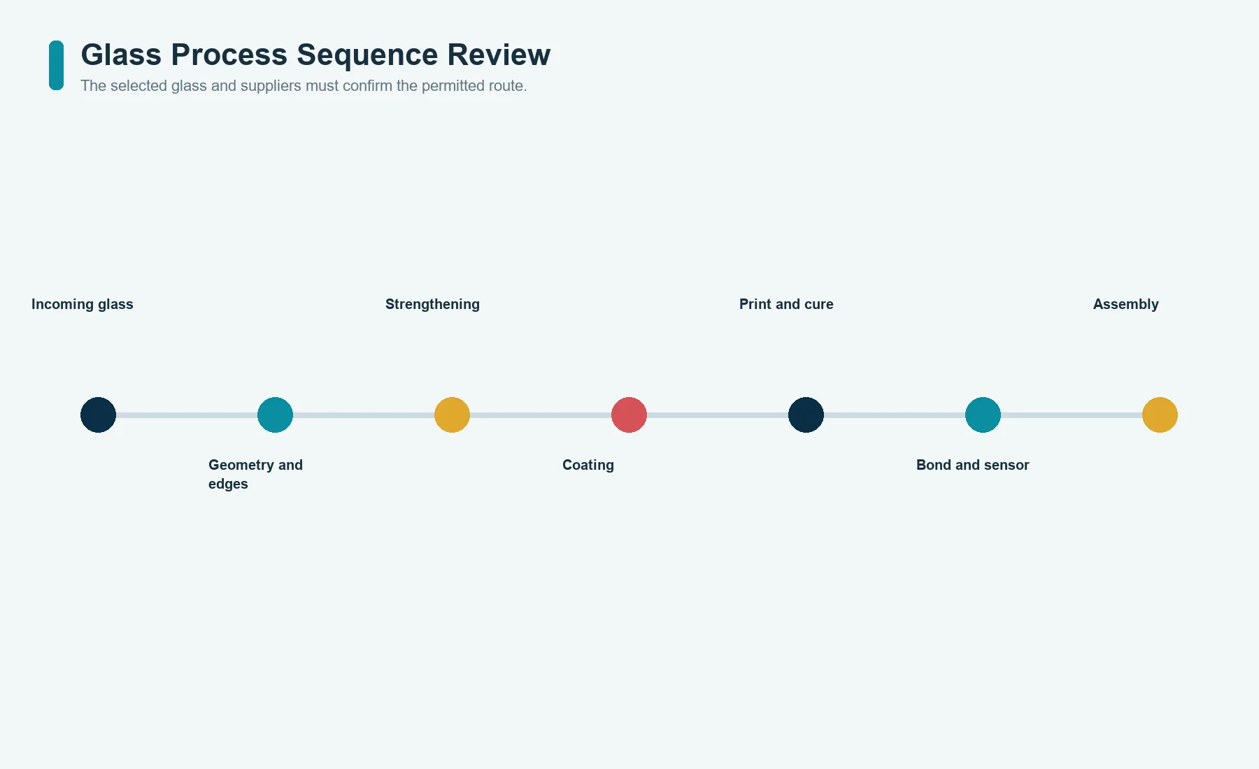
The drawing may request printed graphics, strengthened glass, holes, edge finishing, coatings, and adhesive as if they were independent line items. They are not. The permitted order depends on the selected glass and processes.
ASTM C1036 is a specification for flat glass, and ASTM C1048 covers heat-strengthened and fully tempered flat glass.[8][9] ASTM C1954 addresses decorative enamels on flat glass used in architectural applications.[10] These standards can clarify material and process vocabulary. They do not release an HMI cover, define JASPER capability, or determine the correct sequence for a small control panel.
Before tooling, confirm:
- which geometry must be completed before a heat-treatment step;
- whether later cutting, drilling, grinding, coating, or rework is permitted;
- whether the selected print survives or participates in the thermal process;
- whether a coating or strengthened surface changes adhesion or printing;
- which face receives print, coating, adhesive, and touch sensor;
- how edge, hole, notch, and corner quality will be inspected;
- how glass orientation and surface identity remain traceable.
The correct answer may force an artwork, material, or assembly change. That is better than approving attractive artwork that cannot follow the intended glass process route.
The Inspection Fixture Is Part of the Optical Definition
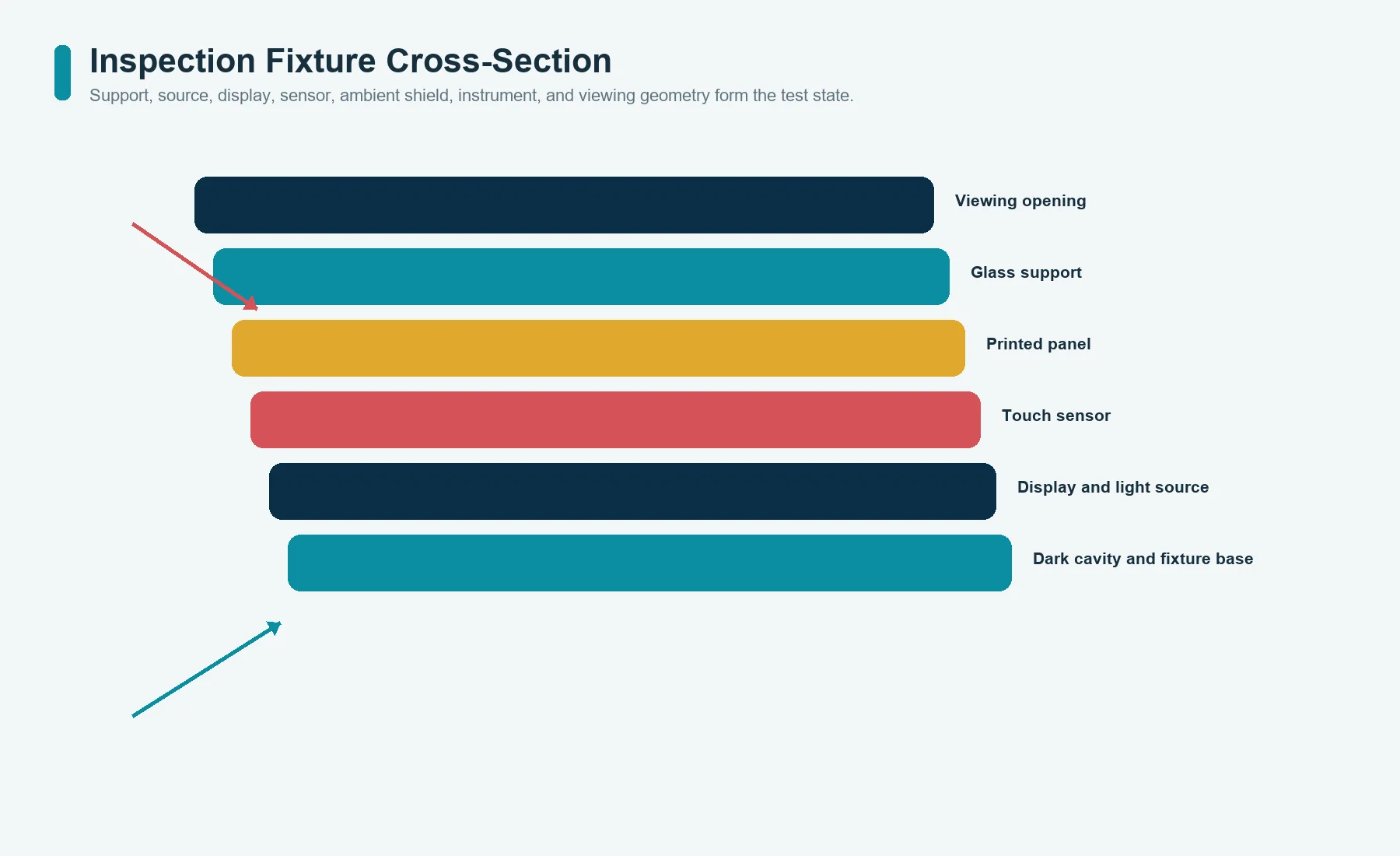
Flexible films can often be placed over a light box. A rigid glass control panel still needs a fixture that reproduces the meaningful support, backing, light location, display location, and viewing geometry.
The fixture record should show:
- product datums and locating method;
- glass support points and allowed clamping;
- dark cavity, reflector, diffuser, LED, and display geometry;
- sensor and controller configuration where touch is checked;
- ambient shield and controlled viewing opening;
- instrument or camera location;
- powered test patterns and stabilization sequence;
- surface cleaning and handling method;
- fixture revision and calibration or verification record;
- master, limit sample, or digital reference authority.
Avoid a fixture that bends or stresses the glass differently from the product. Avoid opaque supports that cover leakage paths. Avoid a generic white light box for a panel whose product uses colored indicators, segmented light guides, or a display with a particular black level.
The fixture is not merely factory equipment. It is a physical interpretation of the acceptance requirement. Its drawing and revision belong with the panel record.
Inspect OFF Leakage Before Turning Anything On
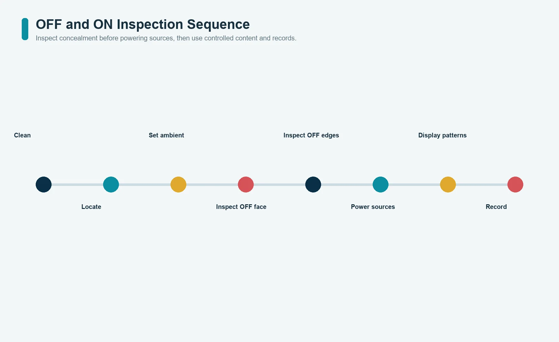
Starting with the powered panel can adapt the observer’s vision and hide weak OFF-state contrast. Inspect the unpowered condition first.
A useful sequence is:
- clean and condition the approved glass stack;
- install it on the defined fixture or representative assembly;
- verify internal sources are off;
- set the ambient and viewing geometry;
- inspect or measure the full face;
- inspect icon centers, edges, corners, and neighboring transitions;
- record pinholes, patches, rear-structure visibility, and surface artifacts;
- compare against the approved limit method;
- preserve the sample identity before powering the unit.
Do not correct OFF leakage only by adding more ink. First determine whether the failure is transmission, color, pinhole, rear structure, reflection, or layer misregistration. More ink in one region may change cure, print step, adhesion, ON brightness, touch behavior, or display-window balance.
Inspect ON and Display States With Controlled Content
The powered check should use known source states. Random production screens and changing LED drive make comparisons unreliable.
For illuminated icons, use a controlled sequence that reveals:
- full-icon uniformity;
- individual zone isolation;
- adjacent-zone leakage;
- lowest required drive state;
- highest required drive state;
- color or bin changes if the product permits them;
- viewing-cone behavior;
- interaction with nearby display content.
For a display window, use selected screens such as black, white, primary or diagnostic colors, fine text, edge markers, and any critical product graphics. The exact set depends on the display and application. The purpose is to expose tint, haze, trapped contamination, mask intrusion, clipped pixels, edge bloom, nonuniform bonding, and parallax rather than to produce a flattering demo.
Record source identity, electrical condition, display settings, warm-up or stabilization, ambient condition, viewing geometry, and image-processing settings. A stored reference image should identify its fixture and software revision.
Touch and Assembly Validation Must Use the Powered Product Stack
Touch approval should follow optical inspection on the representative assembly, not on loose glass placed over a laboratory sensor. The installed housing, display, cable, grounding, power supply, and neighboring electronics can change the result.
Use the zone register to connect each printed symbol to:
- sensor electrode;
- controller channel;
- firmware function;
- displayed or illuminated feedback;
- housing aperture or mechanical locator;
- inspection result.
Check both intended activation and unintended response. A panel can pass every target key while producing adjacent-key coupling, false touches during display operation, drift after cleaning, or a weak edge zone. Where moisture, gloves, contaminants, or grounded objects are relevant, define those states and the recovery expected after they are removed.
The project should also decide whether a visual offset is acceptable when touch remains functional, and whether a functional offset is acceptable when the icon appears centered. In most HMIs, those are separate defect classes and need separate limits.
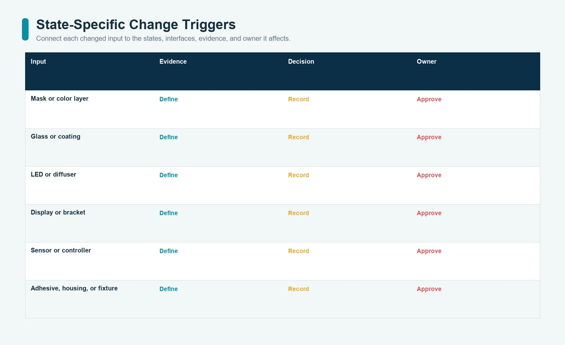
Change Control Must Follow the Affected State
Once a sample is approved, future changes should not trigger the same generic retest. They should trigger the states and interfaces the change can affect.
| Changed item | First affected states | Additional review |
|---|---|---|
| dark mask or support layer | OFF, ON, display | touch, bond step, cure |
| color or translucent layer | ON, display | OFF patch, camera method |
| glass family or surface | OFF, display, touch | edge, strength process, adhesion |
| LED, diffuser, or cavity | ON | OFF rear structure, thermal behavior |
| display module or bracket | Display, assembly | touch noise, mask overlap |
| sensor or controller | Touch | icon alignment, display proximity |
| adhesive, spacer, or optical bond | Display, touch, assembly | bubbles, stress, service |
| housing locator or aperture | Assembly | all optical alignments |
| inspection fixture or software | Inspection | correlation to approved sample |
The release record should use:
Changed Item | Affected Optical Zone | Affected State | Required Evidence | Approval Owner
This format stops a supplier substitution from being treated as paperwork only. It also stops the team from repeating unrelated tests while missing the state that changed.
For the evidence record, use the framework on JASPER’s quality and testing page to connect requirement, specimen, method, result, acceptance, and record. That framework does not prove that a particular glass, ink, light source, display, touch stack, or assembly has already passed.
Dead-Front Glass Is Sometimes the Wrong Construction
Do not force dead-front glass into a project when its main effect conflicts with the operating requirement.
Review another route when:
- the icon must remain visible without power;
- very low available light cannot support the required ON appearance;
- the display needs a clearer optical path than the concealment stack permits;
- the service plan requires frequent removal and the rigid bonded stack creates unacceptable risk;
- the enclosure cannot hold the optical and touch alignment;
- a flexible overlay better fits the weight, impact, curvature, or replacement requirement;
- a direct display with software graphics removes the need for a fixed hidden symbol;
- touch performance cannot be stabilized through the selected cover and assembly.
The existing dead-front membrane-switch article owns the flexible-overlay version of hidden-until-lit icons. GO-03 does not replace it. The choice should follow the complete interface architecture, not a preference for glass appearance.
Send the Optical Zone Package for Review
Submit the glass drawing, layered artwork, optical-zone register, OFF and ON requirements, display active area, touch electrode map, LED and diffuser layout, housing datums, proposed glass and print route, coating, adhesive or bond stack, viewing conditions, inspection method, validation states, quantities, and revision history.
Use JASPER’s request-a-quote page after the package identifies:
- which zones disappear when off;
- which zones illuminate and from what source;
- which window carries display content;
- which graphics align to touch electrodes;
- which datums connect glass, sensor, light, display, and housing;
- how OFF, ON, display, touch, assembly, and inspection states will be accepted;
- what changes require renewed evidence.
That information gives engineering a reviewable optical system. A flattened artwork PDF alone does not.
Frequently Asked Questions
What does dead-front glass mean?
It describes graphics intended to remain difficult to see until a rear light or display is active. It does not by itself specify opacity, transmission, touch, glass, print, or inspection limits.
Can an unpowered glass sample approve the finished panel?
No. OFF, ON, display, touch, assembly, and inspection states expose different failures and need separate acceptance evidence.
How should icons, touch zones, LEDs, and display windows be aligned?
Use one explicit datum chain from the product housing through glass locators, printed zones, sensor electrodes, lights, display, and inspection fixture.
Is ceramic enamel always better than organic ink for glass panels?
No. They are different process routes with different materials, thermal histories, compatibility limits, and change controls. The selected stack and sequence must be confirmed.
What should an OEM send for a dead-front glass review?
Send the glass drawing, layered artwork, optical-zone register, OFF and ON requirements, display active area, touch map, light layout, housing datums, process proposal, assembly stack, inspection method, and quantities.
Sources
- Vibrantz,
Automotive Glass Enamels, official product technical data: https://vibrantz.com/wp-content/uploads/2023/02/Vibrantz_PC_Automotive-Glass-Enamels_AUT04_TDS_012023.pdf - Nazdar Ink Technologies,
59000 Series Enamel Plus Screen Ink, official technical data: https://www.nazdar.com/Portals/0/NAZDAR_59000_Series_Enamel_Plus_Screen_Ink.pdf - ASTM International, ASTM C1649,
Standard Practice for Instrumental Transmittance Measurement of Color for Flat Glass, Coated Glass, and Glazing Materials with Diffuse and Specular Transmittance: https://store.astm.org/c1649-25.html - ASTM International, ASTM E1164,
Standard Practice for Obtaining Spectrometric Data for Object-Color Evaluation: https://store.astm.org/e1164-23.html - ASTM International, ASTM E308,
Standard Practice for Computing the Colors of Objects by Using the CIE System: https://store.astm.org/e0308-18.html - Texas Instruments,
CapTIvate Technology Guide - Design Guide, official controller-manufacturer documentation: https://software-dl.ti.com/msp430/msp430_public_sw/mcu/msp430/CapTIvate_Design_Center/1_83_00_08/exports/docs/users_guide/html/CapTIvate_Technology_Guide_html/markdown/ch_design_guide.html - ASTM International, ASTM D2244,
Standard Practice for Calculation of Color Tolerances and Color Differences from Instrumentally Measured Color Coordinates: https://store.astm.org/d2244-16.html - ASTM International, ASTM C1036,
Standard Specification for Flat Glass: https://store.astm.org/c1036-25.html - ASTM International, ASTM C1048,
Standard Specification for Heat-Strengthened and Fully Tempered Flat Glass: https://store.astm.org/c1048-25.html - ASTM International, ASTM C1954,
Standard Specification for Decorative Enamels on Flat Glass: https://store.astm.org/c1954-26.html
Ready to Start Your Project?
Tell us about your membrane switch, keypad, or graphic overlay requirements. Our engineering team will review your specifications and provide a detailed quote.