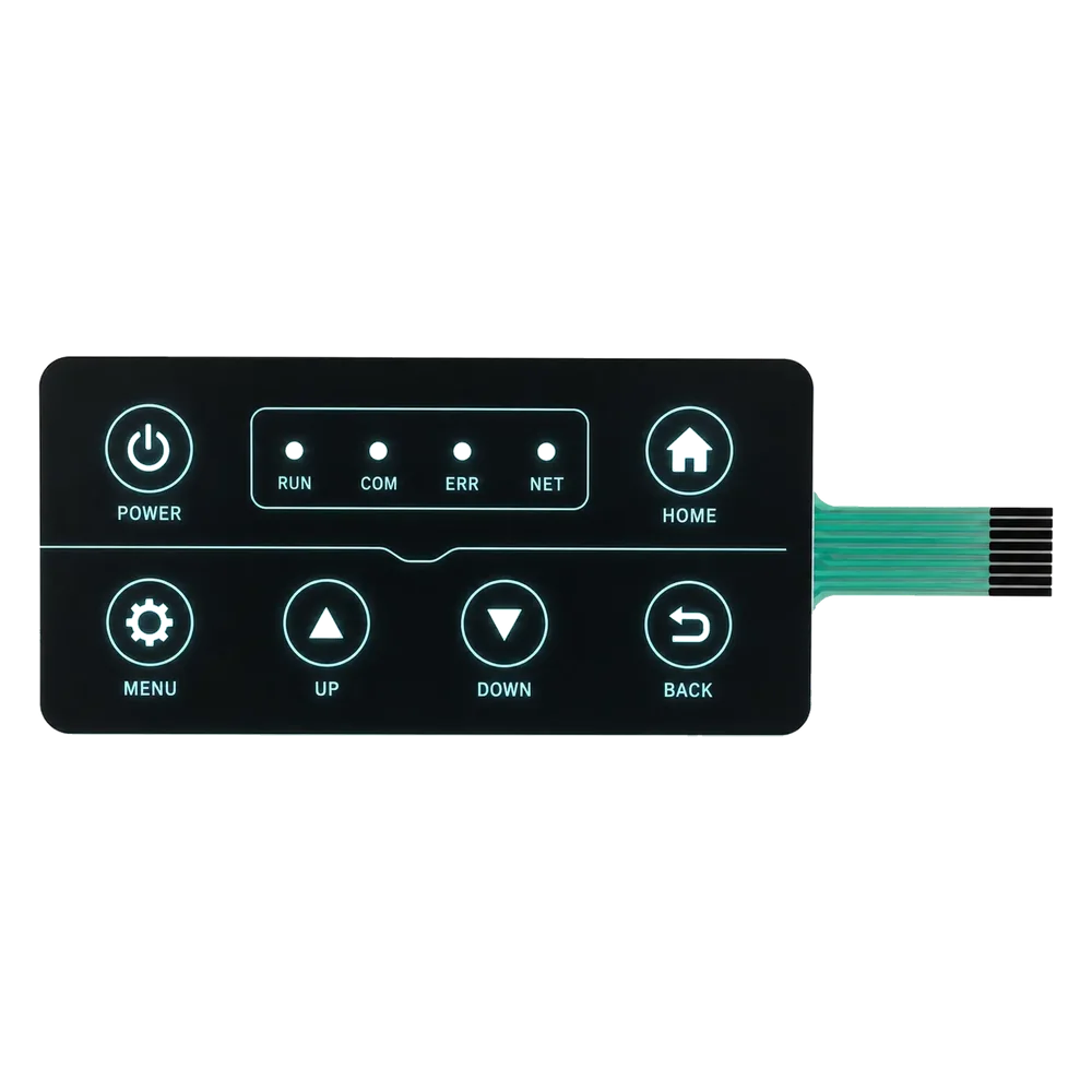
A dead-front membrane switch is a thin-film keypad whose printed icons stay invisible against an opaque overlay until an LED behind the panel switches on, revealing them through a deliberately engineered window of partial light transmission.
1. What a Dead-Front Membrane Switch Is
A dead-front membrane switch is a layered polyester or polycarbonate keypad. Printed graphics (icons, legends, segment cutouts) sit hidden behind an opaque overlay surface. They appear only when an LED behind the panel is energized. The term “dead front” comes from the panel-instrument trade. A dead-front meter face shows a blank surface until its needle or digit is illuminated. That same idea was adapted to flexible membrane assemblies in the late 1990s, once high-output surface-mount LEDs became cheap enough to put behind individual icons on a printed overlay.
One footnote on terminology: “dead-front” also names a separate product family in the electrical-utility business. Eaton and ABB use it for pad-mounted fluid-filled switchgear rated up to 38 kV. Unrelated to the keypad technology described here.
The canonical layered structure of a dead-front membrane switch is five films bonded with pressure-sensitive adhesive:
- Hardcoat or anti-glare top layer — a thin abrasion-resistant coating, typically 5–10 µm.
- Printed graphics layer — second-surface silk-screened icons in translucent vehicle ink.
- Dead-front masking layer — an opaque overprint that hides the icon zone when the backlight is off.
- Spacer + printed circuit — die-cut polyester spacer above a silver-conductive trace on a polyester flex film.
- Rear adhesive — 3M 467MP-class transfer adhesive that bonds the stack to the host enclosure.
Cross-section diagram alt-text: a five-layer membrane stack viewed edge-on, the dead-front mask drawn as the third layer, an LED light source positioned behind the circuit substrate, and the icon outline visible only as a controlled opening in the mask.
2. How Hidden-Until-Lit Icons Are Printed
The dead-front effect is not magic. It comes from a controlled imbalance of light transmission across two regions of the same overlay. The icon shape lets enough light through to read when lit. The surrounding background blocks almost everything. Setting that imbalance takes a five-step silk-screen sequence on the production floor.
Step 1 — Print the icon graphics in translucent vehicle ink on the second surface of the overlay. Second-surface printing is shop terminology for putting the ink on the underside of the clear film. The overlay protects the ink from cleaning chemicals and finger abrasion. Pigment choice is neutral grey, smoke, or white. Transmission lands between 15 % and 25 % when measured against a calibrated white. Marabu MIP, Coates AT, and the Nazdar 9700 family are the screen inks usually cleared for use on PET overlays.
Step 2 — Overprint a dead-front masking layer in opaque ink. The recipe is a dense black or charcoal grey loaded with carbon-black or titanium-dioxide pigment. This mask covers everything except the icon outline. Its light transmission target sits at 3–5 %. So the contrast ratio between the 15–25 % icon zone and the 3–5 % background is what makes the icon visible to the eye under backlight, and invisible when the LED is off.
Step 3 — Add a diffuser layer behind the masked icon zones. Two ways to do this. Print a white diffuser ink as a third silk-screen pass. Or laminate a thin film such as 3M Vikuiti BEF / DBEF, die-cut to match the icon shapes. Either way, the diffuser scatters the LED light so the icon reads as a uniform shape rather than a hot spot over the diode.
Step 4 — Apply the hardcoat or anti-glare top finish to the first surface of the overlay. Industrial keypads get a matte hardcoat with 60° gloss between 4 GU and 12 GU. Consumer appliances tend to take a glossy hardcoat instead.
Step 5 — Cure, register, and laminate. Each ink pass is UV-cured at roughly 200–400 mJ/cm². Registration tolerance between layers must hold within ±0.1 mm or the masking layer will creep over the icon edges and the print becomes scrap. The finished overlay is then laminated to the printed circuit using 3M 467MP, 468MP, or an equivalent acrylic transfer adhesive.
A common shortcut is to add a diffuser film instead of printing a diffuser ink. That moves the dead-front effect off the silk-screen line and into a die-cut converting step. Trade-off: wider viewing angle, but tighter icon-edge definition is harder to hold.
3. Materials Needed for a Dead-Front Keypad
Five material categories drive cost and performance. The overlay film. The ink system. The diffuser. The LED light source. The adhesive. Of those, the overlay film carries the largest single material spec, because it sets surface durability, chemical resistance, and how cleanly the printed image registers.
| Material | Common choice | Typical use case |
|---|---|---|
| Overlay film, autotex / hardcoat PET | Autotex F200 or equivalent, 0.18 mm | Industrial, medical, restaurant — most common |
| Overlay film, polycarbonate | Makrofol DE 1-1 or Lexan HP92W, 0.20–0.50 mm | Higher impact resistance, automotive interiors |
| Overlay film, PMMA / acrylic | Plexiglas 8N, 0.5–2.0 mm | Premium appliance, glossy capacitive panels |
| Translucent icon ink | Marabu MIP, Coates AT, Nazdar 9700 series | UV-cured, screen-printed at 305 mesh |
| Dead-front masking ink | Black PET-compatible UV ink (carbon-black loaded) | Opaque overprint, 3–5 % transmission target |
| Diffuser | Printed white diffuser ink or 3M Vikuiti BEF / DBEF | Scatters LED light into a uniform icon glow |
| LED light source | SMT LED, 3.0–3.4 V Vf, 10–20 mA If | Direct under-icon mount on the FPC or PCB |
| Light-guide film (optional) | Polycarbonate LGF, 0.3–0.5 mm | Edge-lit panels where LEDs cannot sit under each icon |
| Circuit substrate | Polyester FPC + silver-conductive ink | Flex circuit for shallow profile assemblies |
| Adhesive | 3M 467MP (2.0 mil) or 468MP (5.0 mil) | Acrylic transfer, bonds overlay to spacer and assembly to enclosure |
The translucent-ink-and-opaque-mask combination accounts for roughly 60 % of the visual quality. The diffuser and the LED placement together account for the remaining 40 %. Overlay film choice rarely affects the dead-front effect itself. What film choice does set is chemical resistance and abrasion life. A PET overlay cleaned with isopropanol survives roughly 50,000 wipes before hardcoat wear becomes visible. A polycarbonate overlay without an autotex finish survives closer to 10,000.
For medical applications subject to ISO 10993 biocompatibility review, both Autotex F200 and Makrofol DE 1-1 carry supplier-issued biocompatibility declarations. Confirm the specific lot grade in the RFQ before the first PPAP build.
4. Backlight Engineering and Light Transmission
A dead-front panel only looks right when every illuminated icon reads at the same brightness. The industrial target is 100–300 cd/m² across the icon area, measured perpendicular to the surface with the LED running at its nominal forward current. Drop below 80 cd/m² and the icons get hard to read under ambient daylight. Push above 400 cd/m² and the dead-front effect washes out, because light bleed-through around the masking layer becomes visible at the icon edge.
Two LED layouts dominate the production catalog. Direct under-icon mounting places one SMT LED on the FPC behind each icon. Straightforward to drive. Risk is a hot spot if the diffuser layer is too thin. The other approach is edge-lit, which routes LEDs along the panel edge into a polycarbonate light-guide film. The LGF fans light across the entire icon array. It adds about 0.3 mm of stack height. Edge-lit is the preferred choice when icon density is high or the host PCB cannot dedicate space to per-icon LEDs.
LED color on most industrial panels follows ANSI Z535.1-2017 safety semantics. Red means stop or fault. Amber means caution. Green means ready or safe. Blue signals mandatory action. The forward voltage for SMT LEDs in those colors sits between 1.9 V (red) and 3.4 V (white or blue). Each diode draws 10–20 mA. Constant-current drivers are the convention; constant-voltage with current-limiting resistors works for low icon counts under about 12 LEDs total.
Brightness uniformity across icons should hold within ±15 %. Outside that band, the panel reads as inconsistent. One icon “shouts” over its neighbors and the deliberate calm of the dead-front effect breaks.
5. Dead-Front Variants and Design Choices
Four production-grade variants of the dead-front technique exist. Each one trades cost against visual quality or environmental tolerance, in a slightly different way.
| Variant | How icons hide | Best for |
|---|---|---|
| Printed-ink dead front | Translucent icon ink plus opaque mask | General industrial, lowest cost |
| Diffuser-film dead front | Translucent ink with a laminated 3M Vikuiti film replacing the diffuser print | Wide viewing angles, premium readability |
| Smoked-PC dead front | A tinted polycarbonate overlay (5 %–20 % transmission) provides the masking effect on its own | Sleek consumer aesthetic, no opaque overprint |
| Capacitive + dead front | Glass or PMMA overlay with capacitive sensor traces under the dead-front print | High-end appliance, automotive interior trim |
A smoked-PC overlay shortens the print stack to one or two passes. Only the translucent icon ink is needed, because the overlay tint replaces the opaque mask. The trade-off is a slightly muddier black background under direct daylight, plus a higher film cost. Capacitive-plus-dead-front is the configuration that Miele, Jura, and Bosch use on premium coffee machines and induction cooktops. It carries the longest tool-up time, because the capacitive sensor pattern and the printed icon stack must register against each other within a few hundred microns.
For design engineers spec’ing a new program, printed-ink dead front remains the default. Pull toward one of the other three only when a specific aesthetic requirement (uniform smoked surface, capacitive sensing, ultra-wide viewing angle) demands it.
6. Specifications and Industry Standards
Dead-front membrane switches sit at the intersection of label permanence, polymer flammability, environmental durability, and safety color coding. Every serious RFQ should list the standards below.
| Standard | What it covers |
|---|---|
| UL 969 | Marking and labeling system permanence, legibility, adhesion |
| UL 50 / UL 746C | Polymer enclosure flammability and weatherability |
| IEC 60068-2 | Environmental test methods — temperature cycling, humidity, chemical exposure |
| IEC 60529 | Ingress protection rating (IP54 / IP65 / IP67) |
| ANSI Z535.1-2017 | Safety color code semantics for icon backlighting |
| ASTM D3359 | Cross-hatch adhesion test for printed inks on polyester |
| Pantone Matching System | Color specification convention for graphic overlays |
| ISO 10993-1 (medical) | Biocompatibility evaluation for medical-device-contacting surfaces |
A buyer should ask the supplier for three documents up front. One: the UL 969 declaration of conformity. Two: a sample test report against ASTM D3359, with 4B rating or better as the industry-typical pass line. Three: a specific IP rating backed by the corresponding IEC 60529 test report. Where the device touches skin or sits in a sterile environment, also request the ISO 10993-1 biocompatibility statement, written against the overlay material grade actually used in production. A generic supplier letter is not enough.
7. Frequently Asked Questions
How do dead-front icons stay hidden when the backlight is off?
The opaque mask printed over the overlay reflects ambient room light at 95–97 % opacity. Behind that mask sits the icon, printed in translucent ink at 15–25 % transmission. With no rear illumination, the eye reads one uniform dark surface. Icon contrast is too low to detect against the ambient reflection coming back off the mask.
What materials make the best overlay for a dead-front keypad?
Autotex F200 hardcoated polyester is the default for industrial and medical work. Polycarbonate films such as Makrofol DE 1-1 take over where higher impact resistance is required. PMMA and glass are used for capacitive premium-appliance panels. On all three film families, the standard ink systems are UV-cured screen inks from Marabu, Coates, or Nazdar.
Can dead-front icons be printed in full color?
Yes. Color dead-front uses separate translucent ink passes for each color channel, all printed under a single shared opaque mask. Three to five colors is the typical band. Beyond five, registration tolerance becomes the cost driver. Photo-realistic icons need digital UV-curable inks, not silk-screen.
How bright should the backlight be for a dead-front panel?
Industry-typical is 100–300 cd/m² measured perpendicular to the icon. Uniformity should hold within ±15 % across every icon on the panel. Below 80 cd/m², icons get hard to read in daylight. Above 400 cd/m², the masking layer starts to bleed light around icon edges and the dead-front effect breaks down.
Is a dead-front overlay waterproof?
The overlay itself is a continuous polyester or polycarbonate film, so liquid ingress is not the failure mode. A complete dead-front assembly typically reaches IP54 with a basic adhesive seal. With a recessed-bezel gasket configuration, IP65 is the practical ceiling. For IP67, the build needs both a sealed connector exit and a tightly controlled adhesive perimeter. Doable, but the bill of materials grows.
What’s the difference between dead-front and standard graphic overlay?
A standard graphic overlay shows its icons all the time. The icons are printed in opaque ink on a contrasting background. A dead-front overlay flips that arrangement: icons sit behind an opaque mask and only appear when a rear LED switches on. Switching behavior is identical. The visual experience is opposite when the panel is dark.
Can dead-front icons fade over time?
UV-cured inks on PET typically hold icon legibility through 50,000 cleaning cycles with isopropanol. They also survive 1,000 hours of accelerated UV exposure per ASTM G154 without measurable fade. In real-world service, the dominant fade mechanism is not the ink itself. It is hardcoat abrasion. An autotex matte hardcoat will dull visibly long before the printed icon ever fades.
What’s the typical lead time for a custom dead-front membrane switch?
For a brand-new custom dead-front overlay, allow 4–6 weeks from approved artwork through tooling and first-article approval. After first-article, production runs sit at 14–25 days for batches between 500 and 5,000 units. Adding a photo-tool change mid-run usually costs another 7 working days on top.
Technical note
JASPER Electronics, a custom membrane switch and graphic overlay manufacturer, wrote this explainer. The materials, standards, and process sequence above apply to dead-front overlays from any supplier. No payment or competitive consideration shaped the technical content.
Ready to Start Your Project?
Tell us about your membrane switch, keypad, or graphic overlay requirements. Our engineering team will review your specifications and provide a detailed quote.