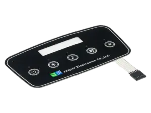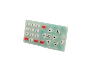

A molded silicone keypad does not automatically include a circuit tail or connector. The silicone part creates the key surface, elastic return, sealing or guiding features, and—depending on the design—the contact or actuator. The electrical tail belongs to the circuit underneath it: a rigid PCB, flexible printed circuit (FPC), printed PET circuit, membrane switch layer, or wire harness.
That distinction matters because “silicone keypad with connector” can describe very different supply packages. JASPER’s silicone keypad assemblies page identifies PCB, FPC, PET circuits, connectors, spacers, adhesives, and testing as possible assembly elements. For quotation and release, define five things explicitly: what is included, where the tail routes, what the pinout is, how the connection is retained and serviced, and how the interface will be tested.
- Define Exactly What Is Included in the Assembly
- Specify Tail Location and Routing Space
- Agree the Pinout and the Mating Connector
- Make pinout approval a controlled interface
- Review Retention, Strain Relief, and Service Access
- Include Connection Tests in Acceptance
- Put the Supply Boundary on the Drawing and RFQ
- Discuss a Hybrid Keypad Assembly
Define Exactly What Is Included in the Assembly
Draw a supply boundary around the parts that will arrive under one purchase order. Do not use “keypad” as shorthand for an unspecified stack.
A loose silicone keymat may have carbon pills or molded actuator features but still rely on the customer’s separate PCB. In that case, there may be no tail or connector on the silicone part. A keypad module, by contrast, can include the rubber, circuit carrier, LEDs, connector, spacers, adhesive, and functional test.
| Circuit structure | Tail / connector interface | Main assembly constraints | Supply boundary to define | Who should verify |
|---|---|---|---|---|
| Silicone keymat over customer PCB | No keymat tail; customer PCB carries connector | Key-to-pad alignment, board support, housing compression | Supplier: keymat; customer: PCB/connector | Supplier: molded/contact geometry; OEM: installed function |
| Silicone keymat + supplied rigid PCB | Board connector, solder pads, or harness | Connector position, component height, mating access | Keymat + PCBA + connector may be one module | Assembly supplier: module; OEM: mating system |
| Silicone keymat + FPC | FPC tail to board connector or another interface | Tail length, bend zone, stiffener, contact side, insertion direction | Keymat + FPC may be supplied; mating connector ownership must be stated | Supplier: tail construction; OEM: mating connector/routing |
| Silicone keymat + printed PET/membrane circuit | Printed tail with exposed contacts or termination | Tail exit, trace routing, contact geometry, fold/handling limits | Supplier may provide complete keypad/membrane subassembly | Supplier: circuit; OEM: host interface |
| Module + discrete wire harness | Header/crimp/soldered pigtail to harness | Wire exit, strain relief, latch access, service removal | Supplier may provide terminated module if agreed | Harness/assembly supplier: termination; OEM: mating half/system |
This is a release checklist, not a promise that every construction is available on every project. Each selected interface needs a drawing, BOM ownership decision, and acceptance method.
For the general taxonomy of ZIF, LIF, crimp, solder-tail, IDC, and related options, use JASPER’s existing membrane switch connector guide. The silicone-specific question is which circuit creates the tail and where the supplied assembly stops.
Specify Tail Location and Routing Space
Tail design is both electrical and mechanical. A correct pinout can still fail at assembly if the tail is trapped by a housing rib, pulled sideways at the connector, or routed through space needed for a gasket, screw boss, battery, or display.
The released drawing should define the tail from a controlled datum and identify:
- exit edge and position;
- tail envelope, length, width, construction, and thickness;
- stiffener and exposed-contact geometry;
- contact side and insertion direction;
- intended bend/fold zone;
- keepout around the contact end and stiffener;
- connector actuator or latch access; and
- routing space for installation and service.
Do not apply a universal bend-radius rule. Flex capability depends on circuit build, layer count, materials, copper layout, and whether the bend is static or repeated. The referenced supplier’s flex-circuit design guide, for example, distinguishes bend guidance by construction and treats dynamic flexing separately. The project drawing should use the actual circuit fabricator’s qualified rule.
Also review the real installation path: how the module is held, whether the connector can be operated after seating, whether the tail must twist to reach the contact side, and how a service technician would remove it. JASPER’s tail-exit design article covers generic exit direction; a silicone assembly additionally needs the three-dimensional relationship among the rubber, circuit carrier, housing compression, connector, and service path.
Agree the Pinout and the Mating Connector
“8-pin ZIF” is not a complete specification.
When the connector is known, record the exact manufacturer family or part number plus the properties that affect the tail: position count, contact pitch, accepted flex thickness, top- or bottom-contact orientation, insertion direction, exposed-contact geometry, stiffener requirement, plating where relevant, and the electrical/environmental ratings required by the product.
Check the exact connector’s drawing and specifications for accepted flex thickness, contact orientation, pitch, position count, FPC/FFC construction and rated mating durability. These details vary by series and part number. Values from one connector must not be copied to another merely because both are described as ZIF.
Make pinout approval a controlled interface
The OEM or system electrical owner should approve the functional signal assignment because the host controller determines what each conductor means. The keypad supplier can implement and test that approved assignment in the PCB, FPC, PET circuit, or harness.
Use the same pin names across the schematic, tail drawing, connector drawing, test fixture, and production test record.
Illustrative example only — not a JASPER production pinout:
| Pin | Signal |
|---|---|
| 1 | ROW1 |
| 2 | ROW2 |
| 3 | ROW3 |
| 4 | ROW4 |
| 5 | COL1 |
| 6 | COL2 |
| 7 | COL3 |
| 8 | COL4 |
A real release should also state connector reference designator, mating part number, pin-1 orientation, contact side, circuit revision, and test-net mapping. If LED power, ground, shielding, data, or other functions share the interface, identify them explicitly.
The PCB and FPC membrane switch route is relevant when the interface needs an etched-copper carrier, denser routing, or integrated circuit structure. The final connector still follows the actual tail and host-board requirements.
Review Retention, Strain Relief, and Service Access
A connector creates electrical contact; it does not automatically provide strain relief for the whole keypad assembly.
Review loads that can reach the interface during assembly, shipping, enclosure closure, vibration, and service. Avoid transferring those loads into exposed traces, the flex-to-stiffener transition, solder joints, or a connector actuator. Depending on the architecture, the design may use a service loop, cable guide, clamp, carrier feature, adhesive restraint, or harness latch.
Check four questions before release:
- Can the tail be inserted without pulling the keypad out of position?
- Can the actuator or latch be operated with the intended tools?
- Does enclosure closure leave the tail untensioned?
- If service is expected, can the connection be released without damaging the tail or silicone part?
For a customer-owned mating connector, the customer should provide the approved manufacturer part number or connector drawing. For a supplier-installed connector or harness, place it inside the supplier boundary on the assembly drawing and BOM. Define ownership of any clip, clamp, or strain-relief feature the same way.
Include Connection Tests in Acceptance
Test the interface that is actually being purchased.
A loose keymat can be inspected for geometry, contact location, force behavior, and rubber-specific requirements, but it cannot prove a customer connector that is absent from the supplied part. A keypad-plus-circuit assembly should add circuit checks; a terminated module should add end-to-end checks through the connector or harness.
Useful acceptance categories include:
- pin mapping and continuity from connector pin to intended net;
- short/open checks using the released circuit criteria;
- key function in the production-intent fixture;
- contact resistance or switch threshold when required by the contact architecture;
- connector orientation and seating, including pin 1 and latch/actuator condition;
- LED or auxiliary circuit function when included;
- routing and retention inspection against the approved installed condition; and
- post-environment function after agreed vibration, thermal, humidity, cleaning, or lifecycle exposure when the product requires it.
JASPER’s carbon-pill guidance already emphasizes measuring the closed switch system under the specified circuit and support condition instead of treating a loose conductive element as proof of system performance. The same boundary rule applies here: do not claim verification of an interface that was not present in the test fixture.
Put the Supply Boundary on the Drawing and RFQ
Mark each item supplier-supplied, customer-supplied, or TBD: keymat, conductive contact, PCB/FPC/PET circuit, connector, mating connector, harness, LEDs, spacer, adhesive, carrier, and final test fixture.
For quotation, provide the keypad drawing, enclosure/routing section, circuit or sample, connector part number or requirements, pinout and pin-1 orientation, tail geometry, service sequence, environmental requirements, acceptance tests, quantities, and any unresolved items. Unknowns can remain TBD as long as they are visible and assigned before tooling or release.
Frequently Asked Questions
Does a silicone rubber keypad normally include a tail and connector?
Not necessarily. A molded keymat may be supplied alone and operate directly on a customer PCB. A tail appears when the assembly includes a flexible or printed circuit, and a connector is included only when the agreed scope includes that interface.
Is the flexible tail molded as part of the silicone?
Usually, no. The signal-carrying tail normally belongs to an FPC, printed PET/membrane circuit, FFC-style circuit, or wire harness used with the silicone keymat. The silicone may provide locating, sealing, or retention features around it.
What is needed to match a keypad tail to a ZIF connector?
Confirm the exact connector family or part number, position count, pitch, accepted flex thickness, contact side, insertion direction, exposed-contact geometry, stiffener requirement, and relevant ratings. Do not assume two ZIF connectors accept the same tail.
Who should own the keypad pinout?
The OEM or system electrical owner should approve the functional assignment because it must match the controller. The keypad or circuit supplier can route, manufacture, and production-test that approved pinout.
Should the keypad supplier also supply the mating connector?
It depends on the purchasing boundary. A supplier can provide a terminated module when that scope is agreed, while many products keep the host-board connector on the OEM PCB BOM. The drawing should identify the division and verification responsibility.
How should a terminated keypad assembly be tested?
Use end-to-end tests that match the purchased scope: pin mapping, continuity, isolation as specified, key actuation, connector orientation/seating, and included LED or auxiliary functions. Add post-environment or lifecycle checks when required.
Discuss a Hybrid Keypad Assembly
If your project combines a molded silicone keypad with a PCB, FPC, printed circuit, LEDs, connector, or wire harness, send the available drawings through the JASPER request a keypad engineering review.
Include the keypad layout, circuit or pinout, host-connector information, enclosure section, quantities, device application, environmental requirements, acceptance tests, and open items. Unresolved decisions can be marked TBD for review before tooling and production release.
Ready to Start Your Project?
Tell us about your membrane switch, keypad, or graphic overlay requirements. Our engineering team will review your specifications and provide a detailed quote.