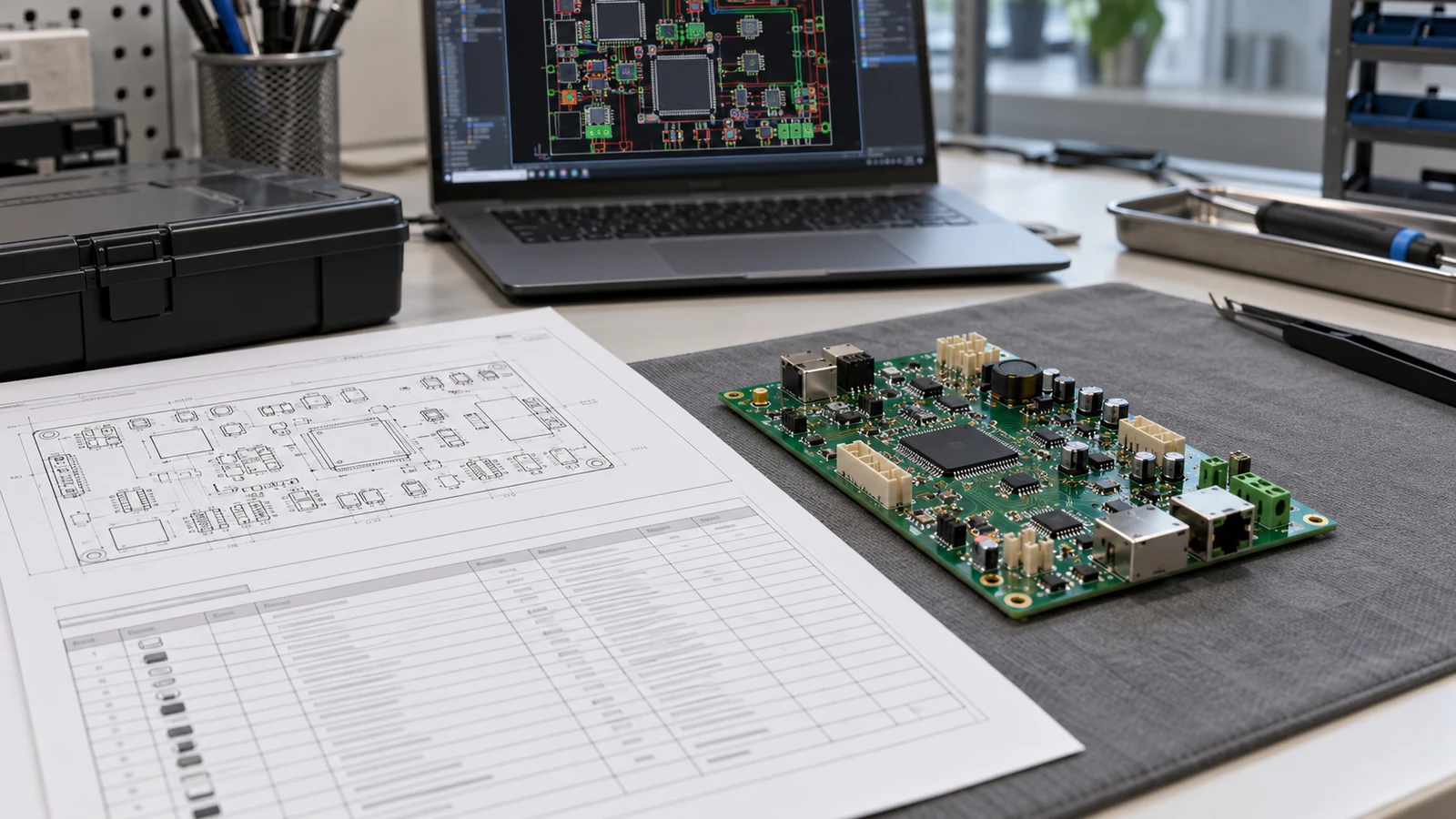
A PCB assembly DFM checklist is a release review that connects each manufacturing concern to evidence, an owner and a decision. Use it to check footprints, orientation, component access, panel handling, soldering, inspection and rework before committing the affected operation. Release only the configuration and build stage supported by the evidence. A corrected drawing can close an orientation conflict; a thermal concern may require a controlled pilot before production approval. A completed checklist is not a guarantee of supplier capability, process yield or product reliability.
- Why a Superficial DFM Approval Can Be Expensive
- Separate Assembly DFM and DFA Questions from Bare-Board Checks
- 1. Review One Configuration and One Agreed Process Scope
- Review Footprints, Spacing and Component Orientation
- 2. Match Every Critical Footprint to the Ordered Package
- 3. Check Working Space, Not Only Body-to-Body Distance
- 4. Resolve Polarity, Pin 1 and Placement Rotation Together
- Check Panel Handling, Fiducials and Board Support
- 5. Review Handling and Separation in the Populated State
- 6. Confirm Alignment Features for the Actual Equipment
- Identify Thermal, Soldering and Hidden-Joint Risks
- 7. Identify the Thermal Window and Its Validation Gate
- 8. Treat Paste, Exposed Pads and Hidden Joints as Linked Questions
- Confirm Inspection, Test and Rework Access
- 9. Connect Acceptance Requirements to Reachable Evidence
- 10. Review the Complete Rework Envelope
- Use the PCB Assembly DFM Checklist as a Review Matrix
- Close Release-Blocking Issues with a DFM Action Register
- Step 1: Freeze the Review Inputs and Define the Gate
- Step 2: Review the Design with the Actual Process Owners
- Step 3: Assign the Risk, Owner and Closure Requirement
- Step 4: Approve Corrections in the Controlled Source
- Step 5: Verify the Disposition Against the Evidence
- Step 6: Issue a Bounded Release Decision
- Worked Action-Register Example
- Eight Signals That Require a Hold or Specialist Escalation
- Prepare the Next Release Review
Why a Superficial DFM Approval Can Be Expensive
A superficial PCB assembly review leaves purchasing and production working from assumptions. Evaluate the proposed manufacturing route, not simply whether a supplier returns a report marked “pass.” Ask what was reviewed, which revision was reviewed and which operations remain conditional.
Consider a connector whose body fits the board but prevents a fixture from reaching a required programming interface. Approving that layout commits the team to a later access change, a different fixture or an altered programming sequence. None of those decisions belongs in an undocumented production workaround.
The commercial question is therefore specific: what expenditure becomes difficult to reverse at the next gate? Separate authorization to buy components, fabricate boards, manufacture tooling, assemble a pilot and release production. A finding may block one operation without blocking every independent activity. Put the affected commitment in the action register so procurement knows exactly what to hold.
Separate Assembly DFM and DFA Questions from Bare-Board Checks
Assembly DFM evaluates whether the populated design suits the intended manufacturing processes. DFA concentrates on how parts are handled, oriented, positioned and assembled. The two overlap; use them as complementary review lenses rather than competing approval certificates. Bare-board review concerns fabrication of the unpopulated PCB and remains a separate workstream.
For example, a fabricator can evaluate a hole against its drilling and plating process. Assembly reviewers must also compare that finished hole with the actual component lead and intended insertion method. Likewise, an electrically connected land pattern still needs review against the selected package and assembly process. Package-specific guidance addresses considerations beyond connectivity alone.
Keep responsibilities explicit. The OEM design authority approves circuit intent and design changes. The assembler confirms the proposed process and its limitations. Quality and test engineering define acceptance evidence. Procurement controls the commercial commitments. A supplier recommendation should return to the responsible design owner rather than silently becoming a new design requirement.
1. Review One Configuration and One Agreed Process Scope
Identify the PCB revision, bill of materials (BOM), component placement list (CPL), assembly drawing and fitted variant as one review baseline. State the planned sequence, including operations performed after the main soldering process. Separate a preliminary feasibility review from authorization to manufacture.
Good signal: The review identifies its input files, intended build stage, included operations and approval owners.
Red flag: A generic DFM report is attached to a quotation without identifying the files or configuration examined.
Keep document-format and variant-management details in their specialist reviews. This checklist needs their resolved outputs, not a second version of the manufacturing-data manual.
Review Footprints, Spacing and Component Orientation
Footprints, spacing and orientation should be reviewed against the exact fitted parts and the operations required around them. Treat a library name, component outline or placement rotation as an input to verification, not as proof that the assembly is correct.
2. Match Every Critical Footprint to the Ordered Package
Compare the manufacturer part number and package code with the land pattern, terminal arrangement, exposed pad, hole requirements and relevant keepouts. Include approved alternate components where they change physical geometry. Treat QFN/SON example footprints as application starting points, and review package-specific features that can affect the layout.
Good signal: The reviewer can trace a critical footprint to the applicable package drawing and explain any intentional departure.
Red flag: The BOM names one package variant while the layout uses a footprint selected only by pin count or nominal body size.
Ask the component or layout specialist to resolve the mismatch before the wrong package or board becomes a purchasing commitment.
3. Check Working Space, Not Only Body-to-Body Distance
Review component envelopes together with placement, inspection, connector mating and rework access. A nominal gap between bodies does not describe every operation. The referenced supplier distinguishes the component boundary, placement courtyard and manufacturing zone; its published clearances belong to its own service context, not to every assembler.
Good signal: The assembler evaluates the actual tool and access requirements, including tall neighbors and parts near the board edge.
Red flag: One minimum distance is applied to every component without checking the operation it must accommodate.
Use the specialist review, Component Clearances for PCB Assembly and Rework, to resolve detailed dimensions. Keep the release register focused on the affected locations, required evidence and decision owner.
4. Resolve Polarity, Pin 1 and Placement Rotation Together
Compare the package drawing, assembly drawing, PCB markings and placement interpretation. Check polarized surface-mount parts, through-hole parts and connectors. The referenced supplier recommends orientation markings that agree with the component datasheet rather than relying on visual symmetry alone.
Good signal: A reviewer can identify the intended orientation from controlled data and confirm the imported placement view.
Red flag: The supplier is asked to infer polarity from a photograph or choose between conflicting drawing and placement instructions.
Correct the authoritative source and regenerate affected outputs. A placement-program edit alone leaves the same ambiguity waiting for the next order.
Check Panel Handling, Fiducials and Board Support
Panel handling must be reviewed for the populated assembly, not just for efficient bare-board nesting. Confirm how the panel will be transported, aligned, supported and separated at the operations that actually use it. Record any required tooling as part of the manufacturing scope.
5. Review Handling and Separation in the Populated State
Check overhanging connectors, heavy components, underside obstructions and access for the intended separation method. The referenced supplier specifically identifies component overhang and panel sagging under heavy components as panel-design considerations.
Request a review of conveyor or carrier engagement, support contact locations and the sequence of operations. Confirm that support does not bear on fitted components or interfere with the planned process. Review the separated board’s handling requirements as well as the intact panel. Assign any required deformation check during heating and separation; room-temperature fit alone should not serve as approval for the complete process.
Good signal: Manufacturing engineering identifies the handling approach, support concept and separation sequence on the panel drawing.
Red flag: Panel approval considers board quantity per panel but ignores fitted parts, support or the final separation operation.
Assign detailed rail, tab and separation decisions to PCB Panelization for Assembly: Rails, Fiducials and Separation. Do not copy another factory’s panel rules into the purchase specification without agreement.
6. Confirm Alignment Features for the Actual Equipment
Fiducials provide optical references for locating and orienting a board or panel during printing and placement. Their implementation must suit the manufacturing route. The referenced supplier describes both panel and individual-board alignment references within its assembly guidelines.
Ask whether the proposed design needs panel-level, board-level or component-local references, and who will approve their visibility and relationship to the placement data. Evaluate both sides when both sides undergo placement.
Good signal: The assembler accepts the alignment strategy in the released artwork and process plan.
Red flag: A reviewer assumes mounting holes, silkscreen dots or a machine specification automatically establish suitable optical alignment.
Use Fiducials in PCB Assembly: Global and Local Alignment Checks for the specialist review. Keep final dimensions and equipment-specific requirements out of a universal checklist.
Identify Thermal, Soldering and Hidden-Joint Risks
Thermal and soldering review should establish whether a workable process is plausible and what evidence must verify it. Do not approve a board solely because a supplier can name an oven setting or has assembled a superficially similar package.
7. Identify the Thermal Window and Its Validation Gate
Review component thermal limits, solder-paste requirements, handling conditions and the proposed operation sequence. Distinguish measured solder-joint temperatures from equipment settings, and establish a profile appropriate to the actual system and board.
Identify locations requiring measurement rather than assuming every component follows the same temperature history. For BGA assemblies, profile selection also depends on board geometry, component arrangement and loading conditions.
Flag layout asymmetry around small passive components for specialist review. Unequal wetting behavior can contribute to tombstoning; a schematic connection alone does not establish thermal balance.
Good signal: The process owner defines the limits, measurement locations and approval gate before a pilot is authorized.
Red flag: A generic reflow curve is presented as completed validation for an unbuilt design.
A new design may need a controlled pilot to establish its profile. Approve that activity explicitly, then retain the production hold until the required results are reviewed. Resolve known incompatible component or process limits before the trial; pilot authorization is not permission to ignore them.
8. Treat Paste, Exposed Pads and Hidden Joints as Linked Questions
Review copper lands, solder-mask openings, paste apertures and via treatment as an interacting system. For LFCSP attachment, board construction, pad geometry, vias, stencil design and soldering conditions all contribute to joint quality.
For bottom-terminated packages, determine which joints the inspection plan must evaluate. Distinguish conventional QFN terminals from side-wettable variants intended to form optically inspectable perimeter fillets. A visible perimeter feature does not make the entire underside visible; specify the evidence needed for the particular acceptance requirement.
Good signal: Package-specific recommendations are reconciled with the proposed stencil, board construction and verification method.
Red flag: An exposed-pad design is accepted because the outline matches, while paste deposition, via behavior and verification remain unassigned.
Escalate detailed stencil, thermal and hidden-joint questions to specialists. Do not turn a package example or a single voiding percentage into a universal acceptance rule.
Confirm Inspection, Test and Rework Access
Inspection, test and rework access must be reviewed before the layout becomes expensive to change. Evaluate access in the assembly state where each operation occurs, including any shields, connectors, fasteners or coatings already installed.
9. Connect Acceptance Requirements to Reachable Evidence
Define which features need inspection and which electrical or functional requirements need testing. Hidden-joint inspection requires an appropriate method; consider X-ray inspection for QFN/SON attachment rather than treating an external visual check as complete evidence.
Build a requirement-to-method map. For each agreed check, identify the observation or connection point, assembly stage, responsible operation and pass/fail record. Ask test engineering to review power connections, programming access, probe approach and fixture support before layout freeze.
Good signal: Every required acceptance check has a defined method and an accessible interface at the planned stage.
Red flag: “Electrical test included” appears in the quotation without identifying the functions, interfaces or acceptance limits covered.
Where access is intentionally unavailable, require an approved alternative or explicit coverage limitation. Do not quietly delete the requirement to match the finished layout.
10. Review the Complete Rework Envelope
Rework access includes more than fitting a tool beside a component. For LFCSP rework, review controlled heating, protection of neighboring parts, bottom-side heating and characterization of the actual board configuration.
Review removal, site preparation, replacement, inspection and retest as one sequence. Identify obstructions above, beside and below the target. Include the condition of the board when rework is expected, not just the uncluttered CAD view.
Good signal: The rework owner accepts a feasible method or the OEM explicitly accepts a non-reworkable location and its replacement strategy.
Red flag: Rework is promised without checking surrounding components, thermal exposure or access for post-rework verification.
Non-reworkable does not automatically mean unacceptable. It means the repair limitation and its commercial consequences require an intentional decision before release.
Use the PCB Assembly DFM Checklist as a Review Matrix
The PCB assembly DFM checklist below assigns each concern to evidence and an accountable owner. Use the specialist follow-up column to route unresolved details; keep the master review as the single record of release status. The rows are review prompts, not declarations that a supplier supports every listed operation.
| Review Area | Question Before Release | Evidence Needed | Responsible Owner | Specialist Follow-Up |
|---|---|---|---|---|
| Release baseline | Are reviewers using the same fitted configuration? | Revision manifest, BOM, CPL and assembly drawing | OEM configuration owner | Manufacturing-data consistency and variant review |
| Footprints and spacing | Do exact packages fit with access for required operations? | Package drawings, footprint comparison and access review | OEM layout lead; assembler consulted | Component Clearances for PCB Assembly and Rework |
| Polarity and orientation | Do drawings, markings and placement interpretation agree? | Pin-1/polarity reference and checked placement view | OEM electrical lead | Polarity and pin-1 review |
| Panel handling | Can the populated panel be transported, supported and separated? | Panel drawing, support concept and separation sequence | Assembly manufacturing engineer | PCB Panelization for Assembly: Rails, Fiducials and Separation |
| Fiducials | Can each relevant operation locate the board correctly? | Alignment-feature review and accepted artwork | Assembly process engineer | Fiducials in PCB Assembly: Global and Local Alignment Checks |
| Thermal balance | Are process limits identified and verification assigned? | Component limits, paste guidance and profiling plan or applicable results | Assembly process engineer | Thermal balance and deformation review |
| Solder-joint accessibility | How will required hidden and visible features be verified? | Joint map, inspection method and acceptance criteria | Quality engineer with process engineering | Hidden-joint and soldering review |
| Test and rework access | Can required checks and approved repairs be completed? | Interface map, fixture/access review and rework disposition | OEM test lead; rework specialist consulted | Test-access and component-clearance review |
Close Release-Blocking Issues with a DFM Action Register
A DFM action register closes the gap between noticing a concern and authorizing manufacture. Each finding needs an affected configuration, consequence, owner, due gate, disposition, verification evidence and approval scope. “Discussed with supplier” is not a closure criterion.
Use three project triage categories: Blocker, Validation risk and Advisory. These are workflow labels, not IPC defect classifications. A Blocker prevents the affected operation. A Validation risk requires defined evidence before its next gate. An Advisory records an improvement or accepted limitation that does not prevent the approved scope.
Step 1: Freeze the Review Inputs and Define the Gate
Record the source-file revisions, fitted variant and proposed route. Specify whether the decision concerns tooling, component purchase, prototype assembly or production. Name the person who can authorize each commitment; do not let a purchasing approval stand in for engineering release.
Step 2: Review the Design with the Actual Process Owners
Walk through the ten evaluation criteria with layout, manufacturing, quality and test representatives. Ask the assembler to distinguish an established process from work requiring tooling, trials or external support. Record exclusions and unresolved interfaces while the relevant owners are present.
Step 3: Assign the Risk, Owner and Closure Requirement
Describe the issue at identifiable reference designators or board locations. State what could go wrong and which operation is blocked. Choose the triage category and define the evidence that would support closure. Set the due gate before requesting a revised design or quotation.
Step 4: Approve Corrections in the Controlled Source
The responsible design authority approves changes to product definition. Update the source design and regenerate dependent manufacturing outputs. Process-only changes belong in controlled process documentation. Recheck affected interfaces; correcting one footprint should not leave the assembly drawing describing its previous orientation.
Step 5: Verify the Disposition Against the Evidence
Use a package comparison, revised drawing or checked import to close a data issue. Use the agreed measurements, inspection results or test records when closure depends on process performance. Assign a competent verifier. An accepted validation plan authorizes the planned investigation; it does not prove the result.
Step 6: Issue a Bounded Release Decision
Choose Hold, Controlled pilot only or Production release. State the revision, fitted variant, authorized operations and remaining restrictions. Production release requires closure or formally accepted disposition of the issues relevant to that gate. Reopen affected findings when the design, part, panel, tooling or process changes.
The decision flow is: controlled inputs → joint review → classified findings → approved corrections → verified evidence → bounded release. A failed verification returns to the responsible owner rather than becoming a purchasing exception by default.
Worked Action-Register Example
This hypothetical register illustrates the method; the identifiers and dispositions are examples, not JASPER manufacturing records. “Due gate” is the operation that cannot proceed without the required disposition. “Evidence” identifies a controlled record, while “approval scope” states what that record actually authorizes.
| Issue and Consequence | Risk and Due Gate | Responsible Owner | Disposition and Evidence | Status and Approval Scope |
|---|---|---|---|---|
| DFM-01: U7 pin 1 conflicts between drawing and placement data | Blocker; before placement programming | OEM electrical lead | Drawing AD-C corrected under ECO-012; checked placement view PNP-C01 agrees with package drawing | Closed by design lead; baseline C placement authorized |
| DFM-02: U9 soldering outcome needs board-specific validation | Validation risk; before production release | Assembly process engineer | Protocol VP-02 defines measurement locations, inspection criteria and production hold; quality lead approves protocol | Validation open; controlled pilot only, no production approval |
| DFM-03: Shielded U3 cannot be reworked after final integration | Advisory; before final design approval | OEM system lead | Service decision SD-03 approves board replacement; access review AR-03 confirms required production tests precede shielding | Accepted by system lead; repair limitation retained in service scope |
Keep the second example open until its results meet the agreed criteria. Protocol approval allows the trial to start; only accepted results can close the soldering concern. The third example is acceptable only because the OEM has deliberately accepted the repair limitation without removing required production verification.
Eight Signals That Require a Hold or Specialist Escalation
Release escalation should be tied to the affected operation and missing evidence, not to the number of warnings in a software report. The following signals warrant a specific hold or an explicitly bounded investigation under the action-register workflow.
| Signal | Required Response Before the Affected Gate |
|---|---|
| 1. Conflicting board, BOM or placement revisions | Hold dependent programming and manufacturing; reissue a coherent baseline. |
| 2. Unresolved package, pin-1 or polarity mismatch | Hold affected purchasing or placement; obtain design-authority resolution. |
| 3. Required placement, mating or repair access is obstructed | Obtain tool/access review and a design change or approved limitation. |
| 4. Populated-panel handling or support remains unproven | Hold the affected operation until manufacturing accepts tooling and handling. |
| 5. No plausible soldering window within component limits | Escalate to process and component specialists; do not substitute a generic profile. |
| 6. Required hidden-joint acceptance has no verification method | Hold production approval; define inspection, acceptance and any authorized trial. |
| 7. Required programming or test interfaces cannot be reached | Hold acceptance release; redesign access or approve a demonstrable alternative. |
| 8. A supplier proposes an unapproved design or material change | Stop affected commitments until the change is reviewed and traceable. |
A capability statement does not resolve these signals by itself. Ask for evidence connected to the proposed board and process. When a concern cannot be resolved within the chosen route, change the design, route or supplier scope rather than hiding the problem in an unconditional purchase order.
Frequently Asked Questions
These PCB assembly DFM and DFA questions address release decisions, approval boundaries and evidence. Apply the answers to the specific build stage under review; prototype authorization and production authorization are different decisions.
What is the difference between DFM and DFA for PCB assembly?
DFM asks whether the populated design suits the intended manufacturing processes; DFA focuses on handling, orientation, positioning and assembly operations. They overlap and should share one action register. Neither replaces the separate review of bare-board fabrication, circuit function, required testing or the OEM’s approval of product definition.
Which DFM issues should block manufacturing release?
Issues should block the affected operation when unresolved data, geometry or process limitations prevent a defined and acceptable build. Examples include conflicting revisions, wrong footprints, ambiguous polarity, obstructed required access and an unworkable soldering route. State the blocked gate explicitly rather than treating every warning as a total project stop.
Does a supplier DFM check replace the OEM’s design approval?
No. A supplier DFM check supports manufacturing decisions but does not replace the OEM’s approval of circuit intent, product requirements or design changes. Keep the responsibilities separate in the release record. A recommended change becomes part of the product only after the designated design authority approves and incorporates it.
How should access for rework be reviewed before layout freeze?
Review the complete removal, replacement and verification sequence around each critical location before layout freeze. Include neighboring components, tool approach, underside access, thermal protection and the board’s assembled state. Obtain the rework owner’s acceptance or record an intentional non-reworkable disposition with an OEM-approved replacement strategy and retained test requirements.
What evidence shows that a DFM concern has been closed?
Closure requires evidence that addresses the original concern and identifies the applicable revision or build. A data conflict may close through corrected files and an independently checked comparison. A process concern may need measured results against agreed criteria. Record the verifier, decision and approval scope; an email acknowledgment alone is insufficient.
Can one component-clearance rule cover the entire PCB?
No. A single distance cannot establish access for every package and operation on the board. Define the object being measured and have the assembler evaluate placement, inspection, mating and rework needs. Use package-specific information and the proposed process to resolve dimensions instead of copying another supplier’s published minimums.
Should DFM and DFA be completed before prototype assembly?
Complete the available design and process-feasibility reviews before authorizing prototype assembly. Resolve known data conflicts and physical blockers first. Where board-specific process evidence can only come from a build, authorize a controlled pilot with defined checks and restrictions. Keep its open validation items separate from closed design issues.
Is a completed thermal profile required before the first board exists?
No. The initial review should establish component limits, a plausible process route and a plan to verify the actual board. A controlled pilot can generate the required profile and attachment evidence. Keep production approval conditional until the designated reviewers accept the applicable results against the project’s agreed criteria.
When should an approved DFM review be reopened?
Reopen the affected review whenever a change can alter its evidence or assumptions. Triggers include a different package variant, revised layout, new panel, altered tooling or changed assembly sequence. Identify which findings require reassessment and retain the previous record, so the next release remains traceable to its actual configuration.
Prepare the Next Release Review
Prepare one controlled package containing the PCB data, BOM, placement file, assembly drawing, fitted variant, panel proposal and required inspection and test scope. Add the open action register and identify the next purchasing or manufacturing commitment. Ask the review team to return dispositions, owners and evidence requirements rather than an unqualified “DFM passed” statement.
For a project discussion with JASPER, use the PCB assembly services page and present that same review package. Confirm the accepted process scope, tooling, inspection, testing and remaining conditions against the proposed design. The useful deliverable is a bounded release decision that engineering, purchasing and production can all act on.
Ready to Start Your Project?
Tell us about your membrane switch, keypad, or graphic overlay requirements. Our engineering team will review your specifications and provide a detailed quote.