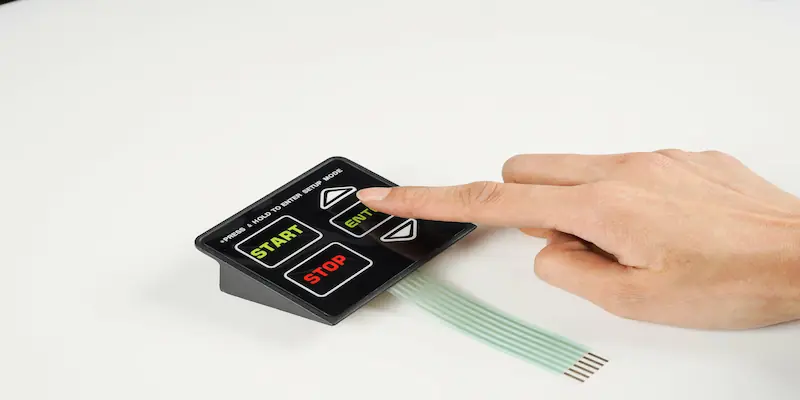
A membrane switch tail is the flat flexible conductor — screen-printed silver-ink on polyester or a copper-etched FPC — that carries every circuit trace from the keypad’s active area to the host PCB connector, making its exit point, direction, and length the first mechanical constraint an engineer must lock in.
- 1. What a Membrane Switch Tail Does — and Why Exit Direction Is the First Decision
- 2. Four Tail Exit Directions Compared
- 2.1 Bottom Exit
- 2.2 Top Exit
- 2.3 Side Exit (Left or Right)
- 2.4 Folded-Under Exit
- 3. Tail Length, Width, and Connector Interface
- 3.1 Tail Length
- 3.2 Tail Width
- 3.3 Connector Termination Options
- 4. Sealing the Tail Exit for IP65 / IP67
- 5. Design Checklist — Six Questions to Answer Before Fixing the Tail
1. What a Membrane Switch Tail Does — and Why Exit Direction Is the First Decision
The tail is the only physical link between a membrane switch and the rest of the electronics. It exits the laminated switch body as a flat ribbon — typically 0.125–0.250 mm thick — and terminates at a ZIF connector, crimp header, or solder pad on the host PCB.
According to Nelson-Miller’s 2012 Membrane Switch Design Guide, engineers have “a great deal of flexibility in selecting the exit point” — but that flexibility disappears once tooling begins. Exit direction matters early because it determines three downstream constraints simultaneously:
- Circuit routing — Silver-ink traces must run from each key position to the tail without crossing. Once the exit edge is chosen, the trace layout is locked.
- Enclosure geometry — The tail must pass through or around the mounting bezel. A bottom exit requires a slot in the chassis; a side exit needs clearance beside the keypad.
- Seal integrity — Every membrane switch rated IP65 or higher (per IEC 60529) must maintain a continuous perimeter seal. The tail exit is the one intentional break in that seal, so its position dictates where the sealing challenge concentrates.
Changing the exit direction after tooling — after steel-rule dies and screen-printing screens are cut — costs USD 800–3,000 in re-tooling and adds 2–4 weeks to the schedule. Specifying it correctly on the first drawing eliminates that risk entirely.
2. Four Tail Exit Directions Compared
Membrane switch tails exit from one of four orientations relative to the keypad’s active area. The System Label Membrane Guide (Version 1.2, August 2023) states that a tail “cannot exit under or within 5 mm (0.200 in) of the active keypad area.” OEM design engineers face these trade-offs at the drawing stage.
| Exit direction | Min clearance from active area | IP seal impact | Assembly complexity | Best-fit scenario |
|---|---|---|---|---|
| Bottom (straight down) | 5 mm (0.200 in) | Minimal — tail routes behind enclosure panel | Low | Rear-mounted PCB directly below keypad |
| Top (straight up) | 5 mm (0.200 in) | Moderate — seal must close above the keypad edge | Medium | Top-access ZIF on a vertical control panel |
| Side (left or right) | 5 mm (0.200 in) | Moderate — seal wraps a 90° corner at the exit | Medium | Horizontal PCB beside keypad in a wide chassis |
| Folded under | 10 mm (0.400 in) fold zone | High — fold creates stress riser and potential seal gap | High | Ultra-thin assemblies with no available edge space |
2.1 Bottom Exit
A bottom exit routes the tail straight down from the lower edge of the switch body. The tail passes through a slot or cutout in the mounting panel and connects to a PCB positioned behind the keypad. This is the most common configuration in industrial HMI panels — Siemens SIMATIC, Allen-Bradley PanelView, and Beckhoff CP-series terminals all use bottom-exit membrane keypads — because it keeps the tail hidden, minimizes bend stress, and preserves the full perimeter seal on the operator-facing side. Minimum recommended slot width: tail width + 1.0 mm clearance on each side.
2.2 Top Exit
A top exit sends the tail upward from the switch’s upper edge. It suits vertical-mount enclosures — such as Crane National Vendors vending machine interfaces or Otis Elevator Series 1 control panels — where the PCB connector sits above the keypad. The trade-off: the seal at the top edge must accommodate the tail passage, which typically requires a pressure-sensitive adhesive (PSA) gasket or a silicone bead around the exit point to maintain IP65 compliance per IEC 60529:2013.
2.3 Side Exit (Left or Right)
Side exits route the tail horizontally. They work well in wide enclosures — 19-inch rack-mount equipment, automotive center consoles (BMW iDrive, Tesla Model 3 HVAC panel) — where the PCB sits beside the keypad rather than behind it. The seal challenge is moderate: the tail must negotiate a 90° turn at the switch edge, and the perimeter adhesive must bridge the gap without creating a moisture path. A 5 mm minimum seal width on both sides of the tail is the industry standard cited by Nelson-Miller and System Label design guides.
2.4 Folded-Under Exit
A folded-under tail doubles back beneath the switch body. It eliminates any visible tail on the front panel and allows connection to a PCB mounted directly behind the keypad — without requiring a chassis slot. The penalty is a mandatory fold zone of at least 10 mm (0.400 in) to keep the bend radius above 1.5 mm for silver-ink tails (per DuPont 5025 silver conductor guidelines) or above 1.0 mm for copper FPC tails. Tight folds below these radii crack conductive traces and cause open circuits within 10,000–50,000 flex cycles.
3. Tail Length, Width, and Connector Interface
Once exit direction is fixed, three dimensions must be specified on the drawing: length, width, and termination style.
3.1 Tail Length
Tail length is measured from the edge of the active keypad area to the insertion point of the connector. The recommended approach: measure the actual routing path inside the enclosure — including any bends — then add 15–20 mm of service slack. Too short forces the assembler to strain the tail during connector insertion; too long creates a fold that can trap moisture or interfere with other components.
For ZIF (Zero Insertion Force) connectors, the tail must extend 4–6 mm past the enclosure wall to reach the connector’s contact zone. Standard ZIF insertion depths — per the Molex 5025 series datasheet (2023) and Hirose FH12 series datasheet (2022) — are 3.0 mm for 0.5 mm pitch connectors and 4.5 mm for 1.0 mm pitch connectors.
3.2 Tail Width
Tail width depends on the number of traces and the connector pitch:
| Connector pitch | Traces per mm of width | Typical tail width (12-pin) | Typical tail width (24-pin) |
|---|---|---|---|
| 1.27 mm (0.050 in) | 0.79 | 15.2 mm | 30.5 mm |
| 1.00 mm | 1.00 | 12.0 mm | 24.0 mm |
| 0.50 mm | 2.00 | 6.0 mm | 12.0 mm |
Silver-ink screen printing holds reliable trace widths down to 0.30 mm with 0.30 mm gaps (IPC-2221A Class 2, Table 6-1). Copper FPC etching achieves 0.10 mm traces with 0.10 mm gaps, enabling narrower tails for high-pin-count designs exceeding 20 traces.
3.3 Connector Termination Options
| Termination type | Mating cycles | Best for | Limitation |
|---|---|---|---|
| ZIF connector (FPC/FFC) | 20–50 insertions | Production volumes, field-replaceable keypads | Requires precise tail thickness (0.20 ± 0.03 mm for most ZIF) |
| Crimp-style header (e.g., Molex KK) | 100+ insertions | Prototyping, frequent disconnect | Adds 5–8 mm height; requires crimped pins on tail end |
| Solder pads (direct to PCB) | Permanent | Cost-sensitive, sealed assemblies | Not field-serviceable; rework requires desoldering |
| Hot-bar bonding | Permanent | High-reliability automotive / medical | Requires specialized equipment; highest connection strength |
4. Sealing the Tail Exit for IP65 / IP67
The tail exit is the single largest vulnerability in a sealed membrane switch. IEC 60529:2013 defines IP65 as “dust-tight + protected against water jets from any direction” and IP67 as “dust-tight + protected against temporary immersion to 1 m depth for 30 minutes.” Both ratings demand an unbroken perimeter seal — and the tail intentionally breaks that perimeter.
Three proven sealing methods at the tail exit:
- PSA gasket wrap — A 3M 468MP or equivalent pressure-sensitive adhesive strip (per 3M Technical Data Sheet, 2024) wraps the tail where it exits the switch body, bonding the tail’s top and bottom surfaces to the enclosure panel. Effective to IP65. Minimum overlap: 5 mm on each side of the tail.
- Silicone potting bead — A dispensed RTV silicone bead (Dow Corning 734 or Momentive RTV108) encapsulates the tail exit zone after assembly. Effective to IP67. Cure time: 24 hours at 25 °C. The bead must extend 3 mm beyond the tail edge on all sides.
- Molded rubber boot — A custom EPDM or silicone boot (Parker Hannifin, Freudenberg Sealing Technologies) clamps over the tail exit and compresses against the enclosure with a mechanical fastener. Effective to IP67+. Higher unit cost (USD 0.40–1.20 per boot in volumes of 5,000+), but allows field replacement of the membrane switch without breaking the seal permanently.
Exit direction affects seal difficulty directly. Bottom exits are easiest to seal because gravity assists adhesive contact and water drains away from the joint. Top exits are hardest — water pools at the seal line under rain or washdown conditions, demanding thicker gaskets or potting.
5. Design Checklist — Six Questions to Answer Before Fixing the Tail
Before locking the tail exit on a membrane switch drawing, the design engineer should confirm:
- Where is the host PCB connector located relative to the keypad mounting surface? (Determines exit direction.)
- What is the routing path length from keypad edge to connector insertion point, including bends? (Determines tail length + service slack.)
- What connector type and pitch will the PCB use? (Determines tail width and thickness tolerance.)
- What IP rating must the finished assembly achieve? (Determines sealing method and minimum seal width at the exit.)
- Will the membrane switch be field-replaceable, or is it a permanent bond? (Determines termination type — ZIF vs. solder vs. hot-bar.)
- What is the minimum bend radius the tail will experience during assembly and in service? (Determines whether silver-ink PET or copper FPC is required.)
Answering these six questions before the first drawing review prevents the most common tail-related re-tooling delays in membrane switch production.
6. Frequently Asked Questions
Where should the tail exit on a membrane switch?
The tail should exit from the edge closest to the host PCB connector. Bottom exits are most common in industrial panels because they hide the tail behind the mounting surface and simplify IP sealing. Side or top exits suit enclosures where the PCB sits beside or above the keypad.
How does tail exit direction affect membrane switch assembly?
Exit direction determines the slot or cutout location in the enclosure, the bend path the tail follows during installation, and the sealing method required to maintain the IP rating. A mismatched direction forces the assembler to fold or strain the tail, risking trace fracture.
What’s the recommended tail length for a membrane keypad with ZIF connector?
Measure the routing path from the keypad edge to the ZIF connector insertion slot, then add 15–20 mm of service slack. For a standard 0.5 mm pitch ZIF (e.g., Hirose FH12), the tail must extend at least 4 mm into the connector’s contact zone for reliable electrical engagement.
Can the tail exit from the bottom of a membrane switch?
Yes. A bottom exit is the default choice for rear-mounted PCBs. The tail passes through a slot in the mounting panel — slot width should equal tail width plus 1.0 mm clearance on each side. Bottom exits benefit from gravity-assisted sealing and minimal bend stress.
What is the minimum clearance between the tail and the active keypad area?
Industry practice requires at least 5 mm (0.200 in) between the nearest active key position and the start of the tail. This clearance prevents the adhesive seal from interfering with dome actuation and provides space for the perimeter seal to close around the tail exit.
Does tail exit direction affect IP65 or IP67 sealing?
Yes. Bottom exits are easiest to seal — water drains away from the joint. Top exits are hardest because water can pool at the seal line. Side exits fall in between. All directions can achieve IP67, but top and side exits require thicker gaskets or silicone potting to compensate for gravity working against the seal.
What’s the difference between a silver-ink tail and an FPC tail?
A silver-ink tail is screen-printed conductive ink on 0.125 mm polyester film — low cost, minimum trace width 0.30 mm, minimum bend radius 1.5 mm. An FPC (flexible printed circuit) tail uses etched copper on polyimide — higher cost, trace width down to 0.10 mm, bend radius down to 1.0 mm, and better suited for high-flex or high-pin-count applications.
Should the tail pin-out be decided by the OEM engineer or the membrane switch supplier?
The supplier should propose the pin-out after reviewing the full circuit layout. The OEM specifies the connector type, pitch, and mating PCB footprint; the supplier then routes traces to minimize crossovers and layer count. Fixing the pin-out before the supplier reviews the layout often forces unnecessary multilayer circuits that increase cost by 20–40%.
This explainer was authored by JASPER Electronics, a membrane switch manufacturer in Shenzhen. The engineering guidance above applies to any supplier’s tail design process; readers should verify connector specifications against the ZIF or header datasheet for their specific project.
Ready to Start Your Project?
Tell us about your membrane switch, keypad, or graphic overlay requirements. Our engineering team will review your specifications and provide a detailed quote.