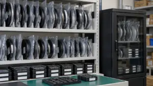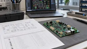
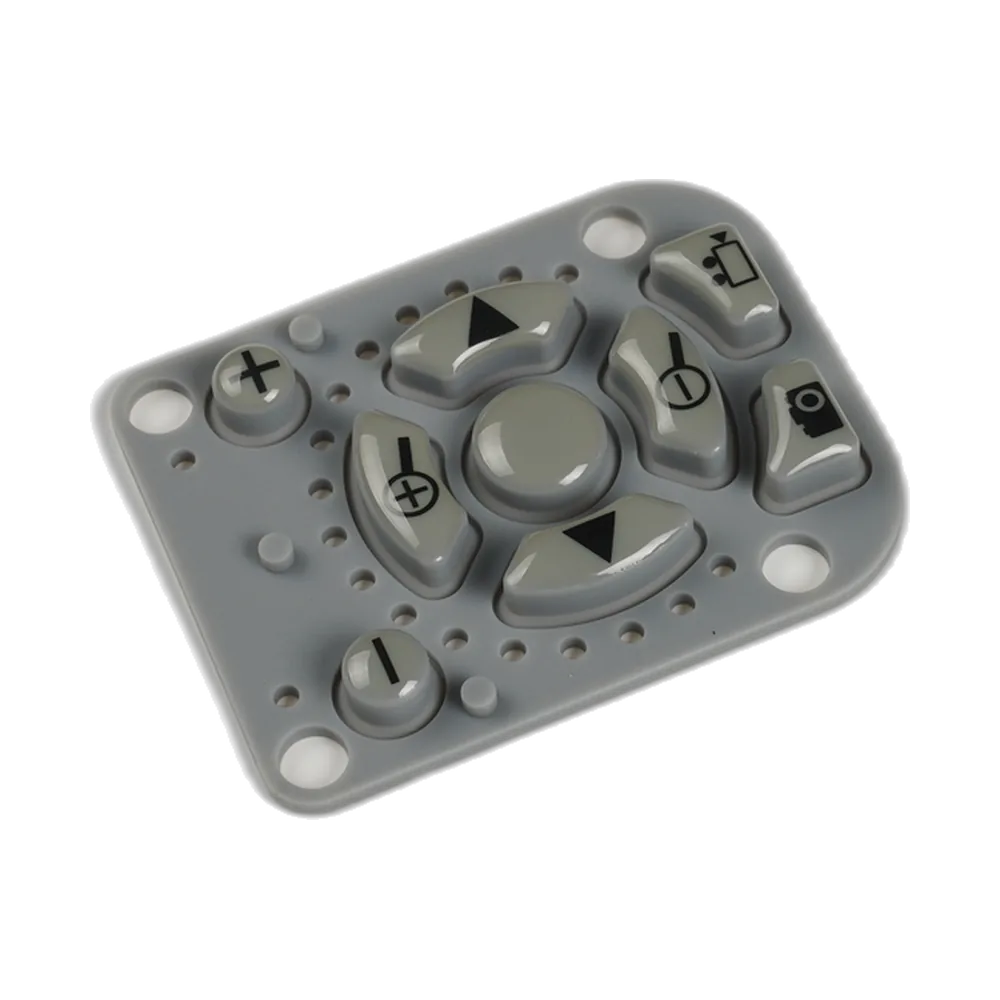
Silicone keypad bezel design should keep each key clear of unintended contact throughout its stroke, hold the stationary keymat without distorting the moving web, and maintain the intended relationship with the circuit. Treat key guidance, retention, sealing compression, and travel stops as separate functions. A keypad that works outside its housing still needs an installed check; JASPER’s silicone rubber keypad design guide provides the broader design framework.
- Define the Keypad, Bezel and Circuit Interfaces
- Review Openings, Clearance and Key Guidance
- Locate and Retain the Keypad without Distortion
- Mechanical retention
- Adhesive retention
- Identify Preload and Mechanical Stops
- Use an Assembly Review Sheet
- Test Return and Feel after Assembly
- Illustrative Example: A Key Becomes Stiff after Bezel Installation
- Request a Keypad Design Review
Define the Keypad, Bezel and Circuit Interfaces
Start with a section through the key, its surrounding opening, the circuit, and the support beneath it. Identify the moving web—the flexible spring section—and distinguish it from stationary mounting lands.
For the assembly review, mark three paths: finger force through the key to the supported circuit; retention force through stationary mounting features; and sealing force through the perimeter seal and mating lands. Show where these paths share a component.
Choose a common rigid datum for height measurements, then identify the features controlling lateral location and rotation. Record which supplier owns each mating dimension. Also identify the switching architecture: a conductive pill approaching PCB contacts needs a different interface review from a rubber actuator driving a discrete switch.
For projects involving several supplied components, review the scope of silicone keypad assemblies before allocating responsibility for the housing interface.
Review Openings, Clearance and Key Guidance
Manufacturer guidance includes bezel clearance, key draft, and air-channel recommendations. Use that guidance as a starting point for discussion, not as approval of your finished assembly.
Dimension the finished key against the finished opening. Specify whether a clearance is per side or a total size difference, and identify the height at which it applies. Check the opening entrance, narrowest guide section, corners, and any shoulder encountered during travel. Include the actual coating and permitted flash in the inspection boundary.
Check center presses and representative edge presses through the full operating stroke and release. A visible gap at the top does not establish clearance farther down the guide. Record where contact occurs and whether it is an intended guide surface or an unintended obstruction.
Do not solve visible key wobble by narrowing every opening. First review locator engagement and the intended guiding surfaces; then validate the proposed clearance against both movement and contact alignment.
Locate and Retain the Keypad without Distortion
Mechanical retention
For a captured flange, pull-through feature, or retaining frame, show the seating surface and assembly direction. Specify which features locate, which retain, and which may float. Consider clearance or a relieved secondary locator where multiple tight features would otherwise require stretching the keymat into position.
Place clamping surfaces on designated stationary lands. During assembly trials, check for lifted corners, trapped folds, and a change in key position as the retainer closes.
Adhesive retention
Treat adhesive mounting as a separate design choice. Differential tapes can combine a silicone-bonding face with a different adhesive on the mating side. Their availability does not establish compatibility with your compound, coating, or housing.
Define the bonding footprint, surface preparation, adhesive orientation, and installed thickness. Exclude removed release liners from the installed stack. Keep the specified bond area outside moving webs and contact cavities, and verify that assembly placement does not obstruct designed air channels.
Identify Preload and Mechanical Stops
Distinguish stationary retention compression, perimeter-seal compression, and an axial bias applied to the moving key. They are not interchangeable acceptance quantities.
To investigate key preload, compare unloaded shoulder and key-top heights with the available enclosure space, using the same rigid datum. Confirm that the keymat seat and circuit support have not moved. A height mismatch indicates geometric interference; it does not state the resulting preload force in newtons. Quantifying that force requires a fixture that isolates the relevant reaction rather than measuring the combined seal and fastener loads.
Separate two kinds of stop. An assembly-closure stop controls the spacing between mating structures. A key-travel stop limits key movement. Check that required electrical closure occurs before the travel stop, that any specified overtravel remains available, and that the stop transfers load through an approved supporting structure.
For a seal, record the unloaded profile and installed land spacing around the perimeter. Set compression limits from the chosen profile and material evidence, not a generic percentage. Assess recovery from compression and flex fatigue separately; material examples do not establish the life of your installed keypad.
Use an Assembly Review Sheet
Use this proposed worksheet during drawing review and again on a representative build. Add the drawing requirement to each row; a blank result is not approval.
Record header: assembly and part revisions; sample/key ID; datum; fixture; fastener condition; conditioning; operator; date. Enter the observation, disposition, and evidence reference in the final column.
| Review item | Check point and method | Acceptance question | Result / evidence |
|---|---|---|---|
| Rest clearance | Inspect opening gaps and contact/actuator position without finger load. | Is the intended rest position maintained without unintended contact or switching? | — |
| Guidance | Observe center and edge presses through travel and release. | Do intended guides work without unintended rubbing or binding? | — |
| Location and retention | Check datum engagement, seating, and orientation before and after fastening. | Is alignment retained without stretching, folding, or lifting the mat? | — |
| Circuit support | Measure local board/support position at rest and during actuation. | Does movement remain within the approved support requirement? | — |
| Key preload | Compare free shoulder heights with installed enclosure space from one datum. | Is any key bias intentional and separately specified? | — |
| Assembly-closure stops | Verify stop seating and local enclosure spacing at the approved fastener condition. | Is closure controlled without unintended local clamping? | — |
| Key-travel stops | Correlate electrical closure, travel, and stop engagement. | Is switching completed before the stop without exceeding approved travel or load? | — |
| Seal compression | Compare free seal profile with installed land spacing, including corners. | Is compression within the approved range without disturbing key motion? | — |
| Designed air paths | Inspect channels after installing retainers, adhesive, and seals. | Are required paths open within the approved sealing boundary? | — |
Test Return and Feel after Assembly
Force-versus-distance testing can record both compression and release strokes rather than only a maximum force when evaluating a keyswitch.
For this review, compare the keypad without its bezel, on its intended circuit/support, with the fully assembled configuration. Keep the probe geometry, press location, speed, conditioning, and travel endpoint controlled. Record force in N and displacement in mm, and document the displacement-zero method.
Log electrical closure and reopening alongside the mechanical record. Distinguish the actuation peak from a later bottoming load, and check final rest height after release. Monitor support movement separately so test-frame travel is not automatically treated as key deformation. Use the tooling and prototype approval guide to carry these records into sample approval.
Illustrative Example: A Key Becomes Stiff after Bezel Installation
All dimensions, forces, and outcomes in this example are hypothetical—not JASPER test results or design limits.
Assume the same key on the same supported PCB has a pre-bottoming actuation peak of 1.80 N without the bezel and 2.50 N after assembly. Edge presses sometimes produce incomplete return. The probe, speed, conditioning, and endpoint are unchanged.
First, preserve the assembled condition. Before loosening anything, record key rest height, circuit/support position, and gaps around the opening. Inspect the full travel path for rubbing. In this scenario, the observed side path remains clear and the support position is unchanged. These observations make a lateral obstruction or support shift less likely; they do not exclude every possible defect.
Next, measure the local retaining interface. Relative to the same rigid seating datum, an unloaded rubber shoulder is 2.40 mm high. With the enclosure on its closure stops, the opposing retaining-rib face is only 2.25 mm above that datum. The shoulder belongs to the moving web region and is intended to remain clear.
The geometric overlap is 2.40 − 2.25 = 0.15 mm. That is an interference calculation, not a preload-force measurement or proof that the key itself moves downward by 0.15 mm.
Then isolate that interface. Use a diagnostic bezel with local rib relief, verifying that opening geometry, locators, circuit support, seal-land spacing, and fastener condition remain unchanged. Suppose the peak becomes 1.85 N and return becomes complete. This supports local clamping of the web as a contributor; it does not prove long-term reliability.
Repeat the comparison against an unmodified control before approving a correction. Recheck retention, switching, stops, and sealing on the revised assembly. Simply loosening screws—or changing rubber hardness first—would not isolate the same cause.
Frequently Asked Questions
Is there one minimum silicone keypad clearance?
Do not release a design from one generic number. Define the mating surfaces, finished condition, inspection height, and permitted offset. Ask the keypad and enclosure suppliers to agree on a project clearance that is verified through travel and release.
Should locating features also clamp the keypad?
Only when both functions are deliberately designed into them. In the review drawing, identify location and retention separately. Check that tightening the assembly does not change the keymat’s seated position or load a moving web.
Does improvement after loosening a screw prove excessive preload?
No. Loosening can change several assembly relationships at once. Treat improvement as a screening observation, then measure the affected interfaces and run a controlled comparison before assigning the cause.
Can a key-travel stop react against the PCB?
Only when the board and its support are explicitly designed and validated for that reaction load. Identify the actual stop surface and support path; do not assume a contact pad or nearby component is a suitable stop.
Does a tight bezel opening establish an IP rating?
No. IEC 60529 classifies protection provided by enclosures, not visual tightness around a key. Evaluate the specified enclosure configuration, including its sealing interfaces and openings; a clearance check is not ingress-test evidence.
Request a Keypad Design Review
Send the keypad and enclosure drawings or sample photos, PCB/contact layout, sections through retainers and stops, seal details, and assembly procedure through request a keypad engineering review.
Include equipment use, prototype and annual quantities, target feel and return, environmental requirements, and any before/after assembly observations. Identify who supplies each component and mark unresolved inputs TBD so the review can focus on the interfaces that still need agreement.
Ready to Start Your Project?
Tell us about your membrane switch, keypad, or graphic overlay requirements. Our engineering team will review your specifications and provide a detailed quote.