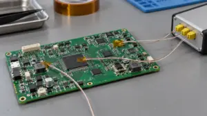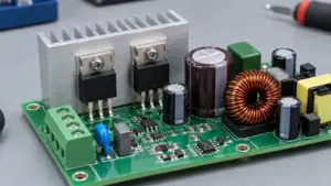
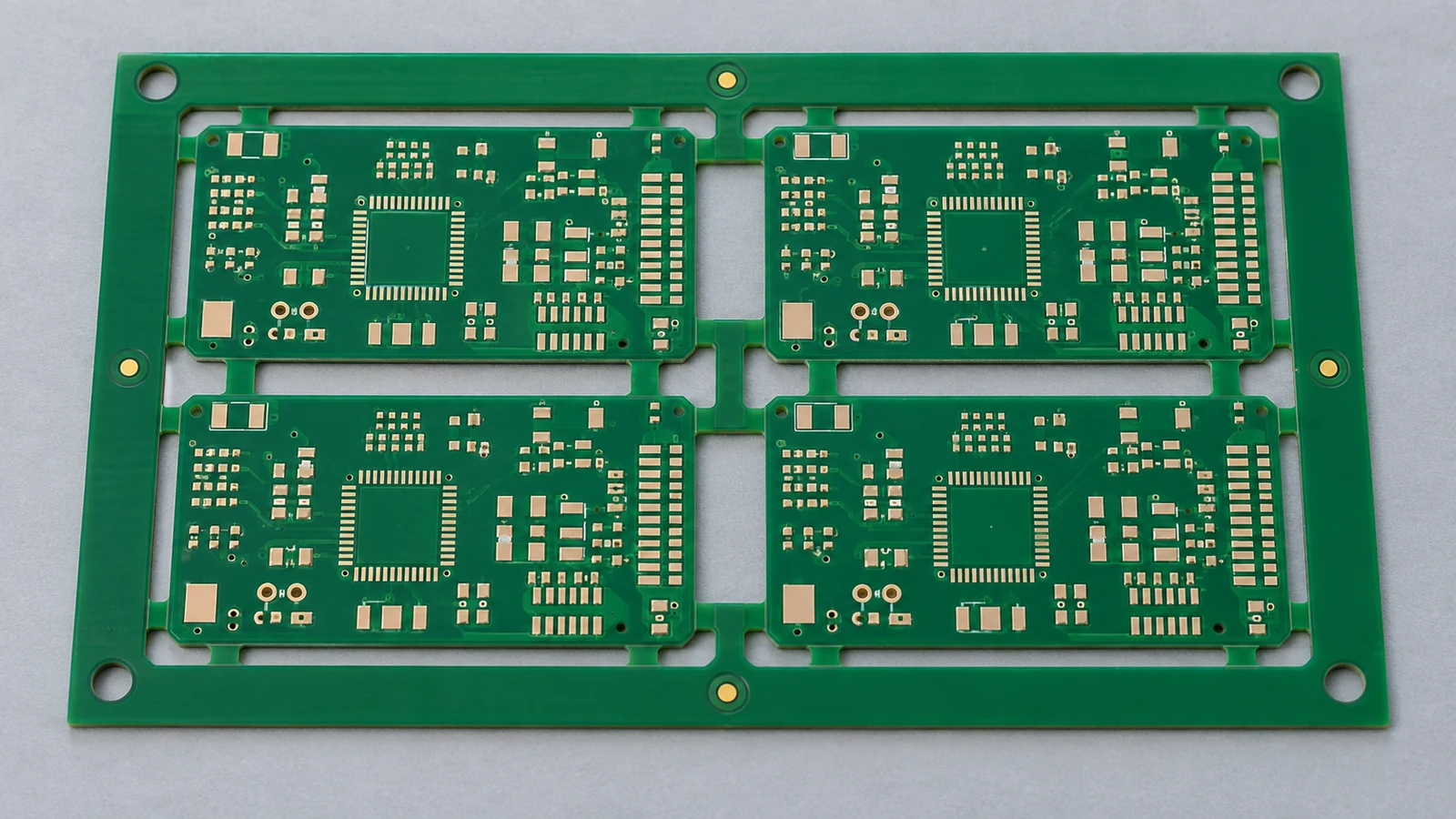
PCB assembly board warpage is out-of-plane board deformation evaluated at a defined manufacturing stage, temperature and support condition. Review incoming shape, thermal behavior, assembly loading and measurement setup separately before deciding whether to accept a lot or change a process. For incoming, unassembled rigid boards intended for surface-mount assembly, a 0.75% maximum for each of bow and twist is a published screening reference, subject to the procurement specification—not a reflow or finished-assembly guarantee. The release decision must also address local soldering requirements and the validated assembly route.
- Separate Incoming Board Shape from Thermal Warpage
- Describe Bow, Twist and Measurement Conditions Clearly
- Use the formula that belongs to the setup
- Make the measurement reproducible
- Review Stackup, Copper Distribution and Assembly Loading
- Check Support and Handling Through the Assembly Route
- Compare Cold and Process-Temperature Evidence Where Needed
- Agree on Acceptance and Escalation Before the Build
- Keep reference limits within their scope
- Assign the decision, not just the measurement
- Five Application Scenarios for the Review
- 1. A thin control-board panel runs flat only when clamped
- 2. A BGA assembly passes incoming checks but shows intermittent opens
- 3. A board changes shape after second-side reflow
- 4. A power board needs a new reflow carrier
- 5. A completed board fits only when enclosure screws pull it down
- Next Step: Prepare a Warpage Review Package
Separate Incoming Board Shape from Thermal Warpage
Incoming board shape establishes the receiving baseline; thermal warpage describes behavior during heating and cooling. A board that meets a room-temperature requirement can still require process-temperature investigation. IPC-9641 explains that the greatest deviation can occur between the initial and final cold measurements, not necessarily at peak reflow temperature.
Start an investigation with separately identified evidence for the delivered board, the production support arrangement, the thermal cycle and the measurement method. A photograph of a bent finished assembly cannot identify which of these changed first. Preserve the lot number, panel position and process history before attempting corrective treatment.
Use this review matrix to prevent unlike measurements from being treated as a single acceptance result. The decisions are a proposed engineering workflow, not additional standard limits.
| Board State | Condition to Record | Measurement Approach | Assembly Risk | Required Decision |
|---|---|---|---|---|
| Incoming unassembled board | Lot, outline, thickness, storage history, ambient temperature and delivered panel format | Agreed bare-board bow/twist procedure; retain orientation and raw readings | Poor transport, stencil contact or placement geometry | Accept against the drawing or contain the lot before assembly |
| Supported panel | Rail span, support-pin coordinates, clamp state, orientation and carrier revision | Compare the same panel before, during and after production restraint | A fixture may conceal the baseline shape or impose a different one | Approve support without replacing the incoming inspection result |
| Heated board | Actual board temperature, time, cycle number and support boundary | Temperature-linked shape measurement over critical regions | Local separation or interference during solder-joint formation | Validate the thermal/support combination or escalate the design |
| First-side assembly | Fitted side, component distribution, first-reflow history and underside access | Cooled baseline plus a representative second-pass evaluation | Changed loading and restricted support access | Confirm second-side handling and reflow readiness |
| Completed double-sided board | Both populations, cumulative cycles and final orientation | Defined cold datum measurement; targeted thermal comparison when needed | Fit problems or unresolved joint-quality concerns | Release only against assembly and interface requirements |
| Post-process board | Exact additional step, such as rework, coating cure, testing or mechanical installation | Matched before/after readings using documented restraint | A downstream operation may introduce or reveal deformation | Isolate the responsible step and approve corrective action |
Record a state only when it exists in the actual route. For example, a board measured after connector insertion should not be grouped with an assembly measured immediately after its second reflow.
Describe Bow, Twist and Measurement Conditions Clearly
Bow and twist describe different shapes, so report them separately. Bow is an overall curve whose corners can remain coplanar; twist puts a corner outside the plane of the other three. Local flatness over a component footprint is a different measurement from either whole-board percentage.
Use the formula that belongs to the setup
For a bow reading, calculate the measured gap divided by the corresponding board length or width, multiplied by 100. Keep longitudinal and transverse results distinct. The board thickness is not the denominator. Under the IPC bow setup, place the convex surface upward and seat both corners of the measured edge against the reference plane; do not press the measured gap flat.
For IPC-TM-650 2.4.22C production twist measurement, the percentage is R / (2D) × 100, where R is the raised-corner gap and D is the diagonal. Three corners contact the reference plane, with restraint applied to only one corner when necessary. The factor of two belongs to this setup; it is not a correction for every optical height map. Use the method’s referee procedure when that contact arrangement cannot be achieved.
As a worked calculation, consider an unassembled rectangular rigid FR-4 board measuring 200 × 150 × 1.6 mm at a recorded ambient temperature of 23°C. A longitudinal bow gap of 1.00 mm gives 0.50%. Its diagonal is 250 mm; a separate production-twist corner reading of 1.00 mm gives 0.20%. These are illustrative calculations, not test results. They do not report transverse bow, hot behavior or final-assembly acceptance.
Make the measurement reproducible
A usable report identifies the specimen and revision, measured area, board side, temperature, prior cycles, conditioning history, datum, restraint locations, instrument and calculation convention. Include raw displacement and percentage where applicable, instrument resolution, repeatability information and the governing drawing requirement. Attach a setup photograph with the support locations visible.
Define whether an optical result is a signed shape, maximum displacement from a datum, or peak-to-valley height across a specified area. State how the reference plane is fitted and which points are excluded. Do not combine a local footprint result in micrometers with whole-panel bow in percent as though they were interchangeable.
IPC-TM-650 2.4.22C covers rigid boards, panels and rigid portions of rigid-flex boards. It explicitly excludes special assembly considerations such as component weight and edge supports. Populated assemblies therefore need a measurement agreement that addresses those conditions.
Review Stackup, Copper Distribution and Assembly Loading
Stackup and copper distribution are investigation inputs, not proof that the bare-board supplier caused the defect. Review the released construction, the delivered construction and the loaded assembly separately. The referenced supplier identifies both production-related and design-related contributors, including asymmetric construction and uneven copper distribution.
Check dielectric and copper thicknesses above and below the board’s center, not just the total layer count. Compare copper distribution within each layer and between corresponding layers. Include the panel border and breakaway regions in that comparison. A balanced-looking board outline does not establish a balanced material stack, and a layout change should be reviewed against electrical requirements before copper is added simply to improve appearance.
Request the actual laminate designation and relevant temperature-dependent material data when thermal deformation remains unexplained. Treat a higher glass-transition-temperature material as a candidate requiring validation, not a guarantee of flatness. Preserve fabrication and storage records so that material, lamination, transport and subsequent handling hypotheses remain distinguishable. Record the as-received shape before baking or restrained flattening. Any proposed corrective treatment needs approval against the laminate, surface finish and populated-component constraints, followed by measurement after release and the relevant subsequent cycles. Do not use a temporary flattened condition to overwrite the original lot evidence.
Mark large packages, connectors, shields and heat sinks with their installation stage on the placement drawing. Treat first-side and second-side loading as different test articles. Repeated thermal exposure can move or detach heavy first-side components during the second pass; assess that loading condition explicitly.
A useful controlled trial changes one major factor at a time: the support arrangement, approved thermal profile, component sequence or board construction. Record the resulting shape and joint evidence together. Changing all four simultaneously may improve yield, but it leaves the team unable to identify which change is essential for repeat production.
Check Support and Handling Through the Assembly Route
Board support must be defined at each operation; a carrier that works for printing does not automatically represent reflow, testing or mechanical installation. IPC-9641 distinguishes clamped support from simple support on rails or a pallet, making the boundary condition part of the evaluation.
For process review, distinguish unclamped datum support, simply supported rails, a simply supported pallet and a clamped carrier. Draw the contacts rather than recording only a fixture name. Show rail spacing, pin positions, clamp engagement and any permitted movement. On a populated underside, identify component keepouts so that the support arrangement can be reproduced without unintended contact.
At paste printing and placement, compare the setup with the panel’s incoming shape. Verify that seating is repeatable and that changing support does not merely transfer the problem to another location. Retain the original incoming result even when the machine holds the panel flat enough to operate.
Evaluate reflow with the actual carrier, loading pattern and orientation. After a fixture change, recheck temperature profile as well as shape using a board representative of production construction and surrounding thermal mass. A flatter cold panel does not prove acceptable soldering conditions.
Continue the review through cooling, unloading, test fixtures and enclosure attachment. Compare measurements before and after any operation suspected of adding load. Where practical, include a non-heated handling comparison to separate mechanical handling from thermal exposure.
A board-wide warpage percentage does not clear localized stress. Review depanelization and heavy-component support separately. Testing, connector insertion and mechanical assembly can impose damaging loads that a final shape measurement does not characterize.
Compare Cold and Process-Temperature Evidence Where Needed
Cold and process-temperature evidence answer different questions. Use thermal measurement when defects, geometry or process changes indicate that a cold baseline cannot resolve the risk. Select the technique for the surface and decision, rather than choosing equipment solely by its advertised resolution.
| Measurement Approach | Appropriate Evidence | Conditions to Control | Interpretation Boundary |
|---|---|---|---|
| Surface plate with gauges | Incoming rigid-board bow and twist at the agreed ambient condition | Contact arrangement, specimen dimensions and applied restraint | Does not capture the reflow shape history |
| Optical or coordinate surface scan | Local or global cold geometry with a defined datum | Measured surface, coordinate system, reference-plane fit and point exclusions | A cold map is not a process-temperature result |
| Heated shadow moiré | Accessible-surface out-of-plane shape during a thermal cycle | Surface visibility, temperature profile and support geometry | Laboratory heating and restraint must represent the intended comparison |
| Heated 3D digital image correlation | Tracking displacement on suitable textured surfaces, including discontinuous assembly geometry | Pattern preparation, calibration, visibility and temperature history | Do not confuse displacement change with absolute initial flatness |
IPC-9641 addresses local board areas through temperature and separates initial shape from thermally induced change. Shadow moiré can measure thermal board shape; digital image correlation can address discontinuous surfaces such as assembled modules. Select and qualify the method for the specimen.
Write the test question before booking the measurement. Examples are whether a component land area changes shape during second-side reflow, or whether an approved carrier changes the relevant deformation. Mark the region on the fabrication data and use the same coordinate convention for each comparison. To calculate temperature-induced shape change, register the surface maps in a common coordinate system and preserve the agreed datum convention. Retain both the original maps and the difference map. Subtracting two peak-to-valley numbers does not produce a point-by-point map of thermal deformation.
Capture starting shape, heating, soldering interval, cooling and final cold state. Log actual specimen temperatures, not chamber setpoints alone. Respect board, component and paste limits: both hot and cold locations must remain within the applicable soldering window.
Separate the measured board surface from the hidden soldering interface. Where a package obscures its land area, document whether evidence comes from an accessible opposite surface, a representative unpopulated specimen or another justified proxy. Do not label an inferred hidden-interface displacement as a direct measurement.
Correlate shape evidence with defect locations and inspection results. Warpage is a hypothesis in an open- or bridge-defect investigation, not a diagnosis by itself. Evaluate other plausible assembly contributors before assigning the cause.
Agree on Acceptance and Escalation Before the Build
A PCB assembly board warpage agreement needs separate receiving, in-process and finished-product decisions. Specify the inspected object, state, method and limit for each decision, together with the person authorized to release an exception. Do not resolve an ambiguous result by choosing whichever measurement produces the smaller number.
Keep reference limits within their scope
Published PCB supplier guidance lists 0.75% maximum bow and twist for boards intended for surface-mount components and 1.5% for other boards. For incoming unassembled rigid-board review, use these as reference categories only when consistent with the controlled procurement documents. They are not two quality grades, a local package coplanarity specification, or permission to accept the same deformation during reflow.
For the illustrative 200 mm board dimension, a contractually selected 0.75% bow limit corresponds to a 1.50 mm gap under the specified bow procedure. That calculation says nothing about the permissible mismatch beneath a small component. Define local assembly criteria from the actual package, soldering process and product interface requirements.
IPC-TM-650 2.4.22 supplies the bare-board measurement procedure; IPC-9641 addresses a different high-temperature evaluation and does not replace it. Record the applicable document editions in the inspection plan. Package drawings and assembly requirements remain separate acceptance inputs.
Assign the decision, not just the measurement
Use the following responsibility matrix as a project-review framework.
| Evidence or Trigger | Decision Owner | Required Decision and Record |
|---|---|---|
| Incoming result exceeds the agreed bare-board limit | Receiving quality with the PCB supplier | Contain affected material; confirm the method and obtain an approved disposition |
| Incoming result passes, but production support changes shape materially | Assembly process engineer | Evaluate fixture contacts and establish an approved support configuration |
| Thermal measurement exceeds a project limit or correlates with joint defects | OEM design and assembly engineering | Review local geometry, construction and process; validate the selected change |
| A new profile or carrier improves shape | Process engineering and quality | Verify soldering and inspection results before revising the controlled route |
| Completed assembly fails fit or needs forced seating | OEM mechanical and quality engineering | Investigate interfaces and loading; authorize disposition rather than forcing assembly |
| Laboratories disagree or the result lies near the limit | Quality and metrology owners | Repeat with a common setup and apply the agreed uncertainty/disposition rule |
Set lot sampling, panel-position coverage, traceability and escalation authority before the build. For a diagnostic study, retain individual specimen results instead of reporting only an average. Agree how repeatability and measurement uncertainty affect borderline decisions; instrument display resolution alone is not the uncertainty budget.
The practical sequence is: preserve the baseline → verify the setup → locate the first state change → test a controlled hypothesis → confirm joint quality and fit → release the documented configuration. Keep a known-good comparison where available, and record why an apparently improved result is sufficient for the intended release.
Five Application Scenarios for the Review
Use these five situations to identify the board states to compare and the evidence needed before release. Each starts with an observation and leads to a specific engineering decision.
1. A thin control-board panel runs flat only when clamped
Compare the panel’s recorded incoming geometry with its shape in the printing fixture and after release. Then evaluate the reflow support independently. The proposed decision is whether the fixture is a validated process aid or an unapproved way of concealing a receiving nonconformance. A successful print is not a retrospective acceptance of the bare board.
2. A BGA assembly passes incoming checks but shows intermittent opens
Preserve affected specimens and map the failed locations. Compare local thermal-shape evidence with package information, paste inspection and the actual profile. Test the warpage hypothesis against competing explanations rather than assuming that a passing global percentage excludes a local problem. Release a corrective change only when the joint evidence supports it.
3. A board changes shape after second-side reflow
Compare the first-side assembly, its second-pass support and the completed board under the same cold measurement convention. Retain both thermal histories and the component installation sequence. The review should identify whether the proposed change belongs to support, sequence, construction or profile, rather than assigning the entire difference to the incoming PCB lot.
4. A power board needs a new reflow carrier
Compare the existing and proposed carriers using equivalent specimens and the approved thermal limits. Check both shape and temperature evidence before accepting the change. Keep the detailed cold/hot-zone optimization within the thermal-balance review; the warpage review must establish which restraint and loading arrangement was actually evaluated.
5. A completed board fits only when enclosure screws pull it down
Measure the assembly before fastening and review the mechanical datums, standoff heights and fastening sequence. Evaluate the imposed load separately from the free or minimally restrained shape. The decision is not simply whether the lid closes, but whether the approved assembly and interface requirements are satisfied without using the enclosure to hide an unresolved condition.
Frequently Asked Questions
These PCB assembly board warpage answers apply the same distinction throughout: identify the board state and measurement conditions before interpreting a result. A receiving criterion does not automatically qualify a thermal process or mechanical interface.
Is room-temperature flatness enough to predict reflow behavior?
No. Room-temperature flatness establishes a baseline but does not show the board’s shape throughout heating and cooling. Use process-temperature evidence when the component geometry, defect pattern or changed assembly route warrants it. Compare the relevant local area under documented support, rather than treating a cold whole-board percentage as a soldering guarantee.
What is the difference between board bow and twist?
Bow is an overall curve with the corners remaining in one plane; twist places a corner outside the plane of the other three. Their calculations depend on different dimensions and contact arrangements. Report longitudinal bow, transverse bow and twist separately, and distinguish them from local footprint flatness.
Can fixture support hide an incoming warpage issue?
Yes. A fixture can restrain a board into an acceptable working shape while its incoming condition still exceeds the receiving requirement. Keep the original inspection result and evaluate the supported condition separately. Fixture qualification should address the intended process, subsequent release from restraint and any necessary exception approval.
How should measurement conditions be reported with a warpage result?
Report specimen identity, revision, board state, measured area, temperature, thermal history, orientation, support and restraint, datum, instrument and calculation method. Include raw displacement, applicable percentage, repeatability information and the acceptance document. For thermal work, attach the specimen temperature history and clearly distinguish absolute shape from change relative to the starting state.
When should thermal warpage trigger a design or process review?
Trigger a review when thermal deformation exceeds an agreed project criterion, correlates with joint defects, disrupts the assembly route or remains unexplained after a support or profile change. Include both design and process engineering when the evidence crosses their responsibilities. A cold inspection pass does not close an unresolved thermal concern.
What bow and twist limit should be used for incoming boards?
Use the controlled drawing and procurement specification for the delivered unassembled rigid board or panel. Published reference categories are 0.75% for boards intended for surface-mount components and 1.5% for other boards. Confirm the method and applicable conditions; neither reference is automatically a hot local-flatness or populated-assembly limit.
Why can a board change shape after the second reflow?
The second pass combines another thermal cycle with a different populated configuration and potentially different support access. Compare the board after the first pass, its second-pass setup and its final condition. Use those records to test specific causes instead of assuming either the bare-board manufacturer or the reflow oven is responsible.
Can baking or clamping permanently fix board warpage?
Not reliably for every cause. Treat baking or restrained flattening as a proposed corrective process requiring engineering approval, not an automatic repair. Preserve the original condition, check material and component constraints, and validate the result after release and relevant processing. A temporary improvement does not establish a permanent solution or lot acceptance.
Next Step: Prepare a Warpage Review Package
Prepare the fabrication drawing, stackup, panel layout, component placement files, assembly sequence, available temperature profiles, support drawings and state-labeled measurements. Add defect locations, relevant package guidance and the acceptance requirements for both the PCB and completed product.
For a project discussion with JASPER, use the PCB assembly services page and bring those inputs together. Ask for agreement on the measurement conditions, investigation owner, required validation and release criteria before the next build. The goal is a repeatable manufacturing decision—not one flat-looking sample.
Ready to Start Your Project?
Tell us about your membrane switch, keypad, or graphic overlay requirements. Our engineering team will review your specifications and provide a detailed quote.