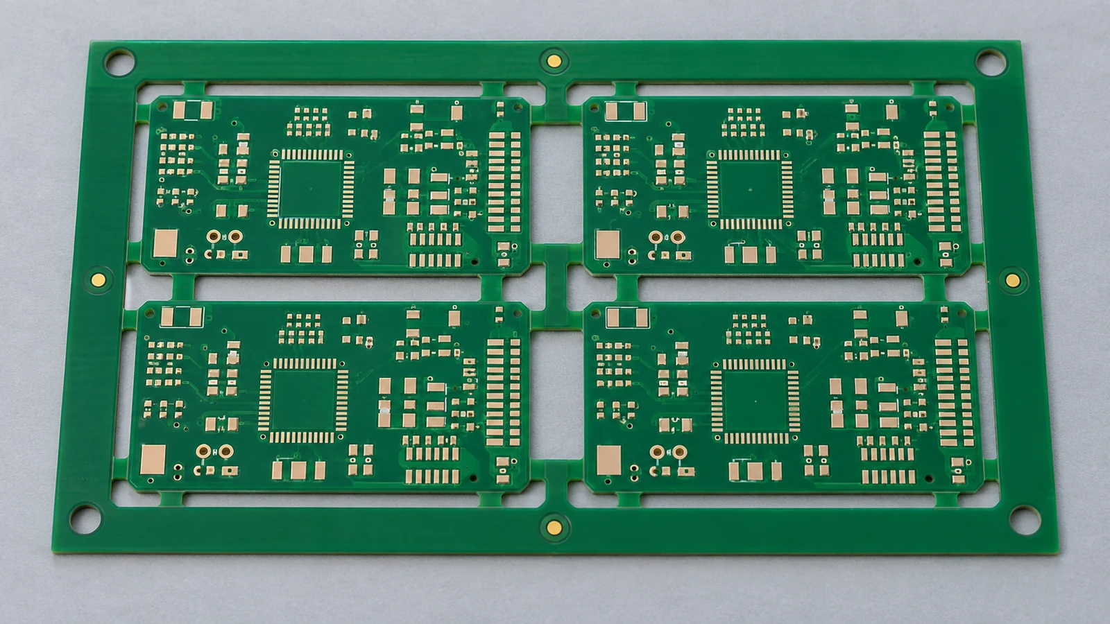
PCB panelization for assembly arranges one or more circuit boards within a temporary handling structure so the assembly line can transport, locate, support and separate them without obstructing components. Approve the panel against the complete manufacturing route, not just bare-board material utilization. The assembler should define equipment interfaces, the fabricator should confirm manufacturable features, and the OEM should approve product and release requirements. A workable panel must remain controllable through the final separation operation, including the moment the last board becomes free.
- Start Panelization with the Assembly-Line Handling Limits
- Provide Rails, Tooling Features and Conveyor Clearance
- Place Panel and Board Fiducials for Reliable Alignment
- Balance Board Support, Orientation and Component Overhang
- Choose Separation Features Around Component Stress
- Approve a Panel Drawing with Assembly and Depanelization Inputs
- Specify the Production Interfaces and Acceptance Basis
- Apply the Rules to Five Assembly Scenarios
- Small sensor boards below direct-handling limits
- HMI boards with edge connectors
- Double-sided boards carrying heavy components
- Mixed-design panels for a product kit
- Instrument boards with sensitive parts near an edge
- Prepare the Panel Review Package
Start Panelization with the Assembly-Line Handling Limits
An assembly panel must fit every operation that handles it, including any carrier used around it. Start with the actual printer, placement machine, reflow transport, inspection equipment, test fixture and depanelizer. A placement machine’s maximum board size alone does not establish a usable production envelope.
Distinguish three objects: the fabricator’s production panel, the assembly panel delivered to the line, and a reusable carrier or pallet. Their dimensions and functions can differ. Specify which object each machine will receive, which side faces upward and which edges contact the conveyor.
The following YRM20 placement-machine and YRP10 printer dimensions illustrate configuration-specific equipment limits. They describe those machine models, not JASPER’s installed equipment or accepted panel limits.
| Equipment and configuration | Minimum L × W, mm | Maximum L × W, mm | Configuration condition |
|---|---|---|---|
| YRM20, one-beam, single-lane standard | 50 × 50 | 510 × 510 | Standard configuration |
| YRM20, one-beam, single-lane option | 50 × 50 | 810 × 510 | Optional long-board capability |
| YRM20, two-beam, dual-stage, one-PCB conveyance | 50 × 50 | 810 × 510 | One-PCB conveyance mode |
| YRM20, two-beam, dual-stage, two-PCB conveyance | 50 × 50 | 380 × 510 | Two-PCB conveyance mode |
| YRP10, single-lane standard | 50 × 50 | 510 × 510 | Standard published size |
| YRP10, single-lane extended size | 50 × 50 | 650 × 510 | Availability requires manufacturer consultation |
| YRP10, dual-lane | 50 × 50 | 420 × 330 | Dual-lane configuration |
Keep length and width tied to the machine’s transport axes. Rotating the artwork does not automatically make an oversized assembly compatible: component overhang, underside features and the configured handling direction also rotate.
As a dimensional screening example, a 600 × 400 mm panel lies inside the listed optional one-beam placement envelope but outside the standard single-lane printer length and dual-lane printer width. This comparison is not a recommended panel size. It shows why a capacity check must identify configurations rather than combine the largest numbers from different brochures.
For a fixed route and orientation, use the largest stated minimum and smallest stated maximum in each axis as the initial dimensional intersection. Then apply the other constraints. Ask the assembler to return a panel-specific envelope covering thickness, mass, top and bottom component heights, edge engagement and support. Include transfers between machines, not only processing positions.
Provide Rails, Tooling Features and Conveyor Clearance
Handling rails provide sacrificial material for transport and clamping when the finished board cannot supply a suitable edge. Their solid width, the adjacent routing channel and the component keepout are different dimensions. Show each separately instead of labeling the entire area “rail.”
For a concrete supplier-specific reference, the referenced supplier describes a 5 mm panel border plus a separate 2 mm break-routing channel, giving 7 mm from the finished board profile to the outer panel edge. Its Customer Panel Basics applies that construction to its own panel service. These dimensions are a review reference, not a universal conveyor requirement or a JASPER capability commitment.
Choose rail width from the actual belt or chain engagement, clamp footprint, panel stiffness and tooling layout. A nominally wide rail is ineffective if routing, holes or cutouts remove the material where a clamp must act. Conversely, an adequate finished-board edge can sometimes provide the handling interface without a detachable rail.
Draw the conveyor contact band on both surfaces. Include clearance above and below the board for clamps, guides, solder joints, connector bodies and lead protrusions. State whether the line uses two opposite edges or a carrier, and preserve the intended leading edge through transfers.
Tooling holes locate the panel or fixture mechanically; they do not replace optical fiducials. Specify hole coordinates, diameter and tolerance, plating condition, datum references and the fixture operation that uses them. The fixture designer should approve the locating arrangement and clearance rather than inherit an arbitrary hole pattern from an unrelated panel.
Keep tooling features accessible until their last required operation. Removing rails before testing, for example, requires a test nest that locates the separated board rather than the discarded panel frame. Put the rail-removal stage in the process route before releasing the drawing.
Place Panel and Board Fiducials for Reliable Alignment
Panel fiducials establish the array’s optical reference, while board fiducials allow alignment to individual circuits within it. Define which reference each process uses; do not assume that recognizing the outer frame proves every board position is correct.
The referenced supplier’s fiducial guidance requires at least three frame targets for its workflow and recommends targets on individual boards. That is a supplier implementation, not a universal minimum specification for every assembly line. Here, “board fiducials” means circuit-level references; component-local targets, where required, serve a separate alignment task.
For the panel review, confirm that targets are visible on each processed side, spread across the useful assembly area and clear of clamps, stencil interference, markings and overhanging parts. Specify copper geometry, mask opening, surface finish and coordinates using the assembler’s recognition requirements. Detailed target sizing belongs in the fiducial design review, not a generic panel-size rule.
Use a common origin and declared orientation for the panel drawing, placement data and inspection programs. Identify every board instance, including its offset, rotation and side. A rotated repeat is not a different circuit revision, but it still requires the correct coordinate transformation.
If production permits an individual circuit to be skipped, define the bad-board identification and program behavior. A camera locating the panel successfully does not establish which units should receive components or which units are acceptable for shipment.
Balance Board Support, Orientation and Component Overhang
Board support must carry the assembly through printing, placement, heating, testing and separation without loading components or obstructing the process. Approve support locations together with the populated board model, not only the bare outline.
During second-side assembly, the first-side components occupy space below the panel. Reserve support lands or use a fixture with suitable pockets; do not place support pins beneath a body merely because the corresponding region looked empty in the unpopulated CAD view. Review the support arrangement again after changing board orientation or component height.
Heavy components and narrow connections between routed circuits deserve particular attention. The referenced supplier’s component influence guidance identifies sagging as a concern and discusses retaining additional material between boards. Decide whether to retain material, reduce the array, add support or use a carrier by reviewing the actual load and process sequence.
A reusable carrier is a separate tool, not an automatic substitute for every rail or support requirement. Define its locating method, retention, component pockets and release sequence. Check its external envelope and thermal behavior as part of the loaded assembly, including whether it remains with the panel through reflow or only a particular operation.
Overhanging components must fit in three dimensions. The referenced supplier warns against placing protruding components over breakout tabs in its overhanging-component guidance. Keep the component body clear of the neighboring board, retained frame, support tool and separation path.
For a spacing calculation, assume opposing bodies project 2.0 mm and 1.5 mm beyond their finished board edges at worst-case tolerance. If the approved process requires a further 2.0 mm unobstructed corridor between those bodies, the corresponding edge-to-edge spacing is at least 5.5 mm. This is a stated geometry example, not a standard routing gap. The corridor must cover the actual tool envelope and remaining process tolerances, not just a cutter’s nominal diameter.
Approve orientation for handling and process access before optimizing nesting. A denser layout that hides a separation tab beneath a connector is not ready for assembly.
Choose Separation Features Around Component Stress
Separation features must match both the fabricated panel and the process used after population. A V-score, a solid tab and a perforated tab create different remaining connections; none independently guarantees a low-stress removal operation. Review the board’s support and restraint throughout the cut, including the final release.
These four practical panel constructions separate feature selection from the later removal method. They are also distinguished in the referenced supplier’s panelization guidance; the approval conditions below should be resolved for the actual product.
| Panel construction | Practical use | Separation process to define | Approval condition |
|---|---|---|---|
| V-scored panel | Straight separation paths where score geometry suits the board | Guided blade separation with a defined support arrangement | Approve score position, residual web, component envelope and complete blade travel |
| Routed panel with solid tabs | Shaped outlines or selective attachment locations | Router cutting or a compatible dedicated tab punch | Confirm access to every tab, retained-board support and finished-edge requirement |
| Routed panel with perforated tabs | A routed outline with deliberately weakened attachment points | Supported breakout or controlled tab cutting, selected through validation | Approve hole pattern, remaining material, breakout direction and residual edge condition |
| Hybrid scored and routed panel | Straight boundaries combined with shaped edges or local relief | A sequenced combination of the approved separation operations | Confirm that the first operation leaves enough support and access for the next |
For V-scoring, specify the groove geometry and remaining web with tolerances rather than relying on a drawing note that says “standard V-cut.” Check the actual blade approach, exit and clearance to tall or protruding components. Do not assume that conventional scoring can stop anywhere along a panel without fabrication confirmation.
The separation machine also has its own envelope. For example, cab lists maximum separation lengths of 450 mm and 600 mm for its two MAESTRO 4S variants. Its guidance also explains that cutting passes and blade adjustment affect stress near the groove. Neither dimension nor a machine description establishes a universal safe component setback.
For routed tabs, identify how the removal tool enters the opening and what restrains the board after each connection is cut. A dedicated punch needs its own matching access and support geometry; cab’s HEKTOR 2 illustrates this distinction. A perforated tab should not become an instruction to twist a populated board by hand. Define how each freed board is captured. When one cut divides the array into smaller subpanels, verify that those pieces still have suitable locating and support features for the next operation.
Set the validation scope according to product risk: cutting trials, edge inspection, relevant electrical checks and strain measurement where required by the component or customer acceptance plan. Keep strain limits and failure analysis in the dedicated reliability review. For panel approval, the essential output is an agreed process, fixture, sequence and acceptance record.
Approve a Panel Drawing with Assembly and Depanelization Inputs
The drawing for PCB panelization for assembly should define a shared manufacturing interface, not simply show how many boards fit together. Assign approval by function: the fabricator owns feature manufacturability, assembly engineering owns line compatibility, tooling engineers own fixtures, and the OEM owns the product requirements and authorized revision.
Use this matrix to close the panel review. Each approval owner must assess the actual drawing and process, not only acknowledge receipt of the files.
| Panel Feature | Assembly Purpose | Constraint to Verify | Required Drawing Detail | Approval Owner |
|---|---|---|---|---|
| Handling rails | Present continuous transport and clamp surfaces | Conveyor engagement, top/bottom clearance, rail stiffness and removal stage | Solid rail width, routing gap, contact bands, feed direction and outer dimensions | Assembly process engineer; fabricator confirms construction |
| Tooling holes | Locate and restrain the panel in the specified fixture | Pin fit, positional tolerance, plating condition and access through the route | Hole size/tolerance, coordinates, datum scheme and fixture reference | Tooling engineer; fabricator confirms hole production |
| Panel fiducials | Establish optical panel position and orientation | Visibility on each processed side and compatibility with recognition settings | Copper targets, mask openings, coordinates, side and exclusion regions | Assembly programming engineer |
| Board orientation | Keep circuit identity and coordinate transformations consistent | Placement, inspection, test access and overhang for every repeat | Instance identifiers, offsets, rotations, side and board-revision reference | Assembly programming engineer; OEM design engineer |
| Breakaway features | Retain boards until controlled separation | Tool access, remaining support, component exposure and final-edge limits | Score/web or tab/perforation geometry, tolerances, sequence and separation method | Depanelization engineer; OEM quality engineer; fabricator |
| Support locations | Carry loads without contacting populated features | First/second-side clearance, heating, test forces and final-cut restraint | Support lands, prohibited contact zones, component heights and fixture reference | Tooling/process engineer; OEM design engineer |
The approval flow is:
Board revision and populated geometry → complete process route → line and fixture constraints → panel construction and separation plan → joint drawing review → representative build verification → controlled release.
Before the representative build, reconcile the panel drawing with board data, placement data, stencil layout, inspection coordinates and the test nest. Identify whether each file describes one circuit or the complete array; do not apply panel offsets twice.
Agree how panel identification maps to individual boards after separation. A label on a discarded rail cannot, by itself, identify the units shipped to the customer. Define the handling of rejected units and any test records that remain associated with each board.
Record changes to rails, pitch, orientation, tabs, scoring and support as controlled panel revisions. If the fabricator regenerates these features during CAM preparation, review the revised geometry before fabrication. An unchanged electrical design does not authorize an unreviewed change to the assembly interface.
Specify the Production Interfaces and Acceptance Basis
Panel specifications should state the interfaces needed to reproduce the approved route: material and thickness, outer envelope, profile tolerances, tooling references, component height limits, support conditions and separation acceptance. Assign dimensions to the finished board, panel or carrier explicitly so inspection measures the correct object.
Identify the contractually required fabrication, assembly and test documents by revision. A general workmanship requirement does not supply a conveyor clearance, fixture pocket depth or allowable tab-removal condition.
Thermal requirements remain specific to the loaded assembly. AN-2029, revision H, distinguishes IPC/JEDEC J-STD-020 device-classification conditions from production reflow settings. A classification profile is not a ready-made panel or carrier recipe. Review the production profile when a panel change materially alters support, thermal mass or airflow around the assembly.
For separated boards, define the accepted final profile, residual tab projection, edge damage criteria and applicable post-separation checks. Release evidence should demonstrate these conditions on the approved construction rather than merely show that boards can be broken apart.
Apply the Rules to Five Assembly Scenarios
Different assembly scenarios change which panel feature controls the decision. Use the following examples as review situations, not as claims of completed customer projects.
Small sensor boards below direct-handling limits
Choose an array or a carrier that gives the line a usable external envelope. Preserve circuit identification and access for programming before deciding how many units to combine. Approval should include a demonstrated handling route and a defined way to restrain the final unit during separation.
HMI boards with edge connectors
Place connector envelopes into the panel model before setting board pitch. Keep tabs and cutting paths out from under connector bodies. Where a connector blocks the preferred separation route, compare another orientation, a larger gap or a later connector-installation operation, including how that operation will be inspected.
Double-sided boards carrying heavy components
Review underside pockets and support lands for the second assembly pass, then revisit the fully loaded panel at testing and separation. A fixture that supports the bare board is not enough. Require the tooling plan to identify which surfaces carry the load at each stage.
Mixed-design panels for a product kit
Combine designs only when the fabrication construction, assembly sequence and process requirements are compatible. Fix the quantity ratio, instance mapping and reject-handling rules. A shared panel ties replenishment quantities together, so procurement should approve the expected kit ratio and disposition of unmatched usable boards.
Instrument boards with sensitive parts near an edge
Escalate the separation review when the proposed score or tab puts a sensitive component near a loaded region. Compare moving the attachment point, changing support or selecting another removal process. Accept the choice against component requirements and a representative validation plan, not a generic distance rule.
Frequently Asked Questions
PCB panelization questions should be resolved against the actual assembly route and the approved product revision. These answers summarize the decisions to close before panel fabrication and production release.
Should the PCB fabricator or assembler define the panel layout?
The assembler should define handling and process interfaces, while the fabricator confirms that the panel features can be manufactured. The OEM approves the resulting product and revision requirements. Either supplier may prepare the drawing, but one party’s drawing preparation does not replace the other parties’ technical approval.
When are assembly rails required?
Assembly rails are required when the finished board cannot provide the transport, clamping, tooling or support interface needed by the chosen process. An adequate board edge or qualified carrier may remove that need. Confirm both populated surfaces and the full route before deciding that rails are unnecessary.
Can several board designs share an assembly panel?
Yes, several designs can share an assembly panel when their board construction and assembly processes are compatible. Define each design’s revision, instance location, quantity ratio and reject-handling rules. Procurement must also accept the linked production quantities, while engineering verifies placement, thermal processing, testing and separation for every included design.
How should overhanging components affect panel spacing?
Overhanging components should set a three-dimensional clearance requirement between finished board edges, neighboring assemblies, rails and tools. Add the opposing worst-case projections and the process corridor required between them. Include relevant tolerances and check the separation sequence; a fabrication routing gap alone does not demonstrate usable assembly clearance.
What must be approved before choosing V-scoring or routed tabs?
Approve the board construction, component envelopes, separation equipment, support arrangement and final-edge requirements before selecting V-scoring or routed tabs. The drawing must define the relevant groove or tab geometry and tolerances. Validate the chosen operation under representative populated conditions, with inspection and additional testing determined by product risk.
Can a reusable carrier replace sacrificial assembly rails?
A reusable carrier can replace sacrificial rails when it provides the required handling and locating interfaces throughout the operations that need them. Verify retention, component pockets, external dimensions, thermal behavior and removal access. A carrier approved for printing alone is not automatically qualified for reflow, testing or depanelization.
Are panel fiducials enough for every board in an array?
Panel fiducials are not automatically sufficient for every circuit in an array. The assembler should determine whether board-level or component-local references are needed for the placement and inspection strategy. Keep required targets visible on each processed side and maintain consistent coordinates between the panel drawing, placement data and machine programs.
What should trigger a new panel approval on a repeat order?
Changes to the panel envelope, rail geometry, circuit pitch, orientation, fiducials, tooling, support or separation features should trigger a panel review. Changes in populated height, mass, production equipment or fixture configuration may also affect compatibility. Document the review outcome and revalidate the affected operations before treating the order as unchanged.
Prepare the Panel Review Package
Prepare the single-board outline and stack-up, current assembly drawing, BOM, placement data and a proposed panel layout. Include populated height and overhang information, required delivery format, test access and final-edge requirements. Ask for the drawing to be reviewed together with the actual handling and separation route.
For a project using JASPER’s PCB assembly services, submit these inputs as one controlled package and identify who will approve the panel revision. Resolve the transport, alignment, support and depanelization decisions before committing to the production panel—not after the bare boards arrive.
Ready to Start Your Project?
Tell us about your membrane switch, keypad, or graphic overlay requirements. Our engineering team will review your specifications and provide a detailed quote.