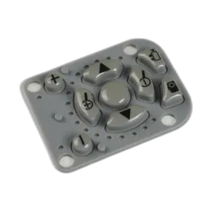
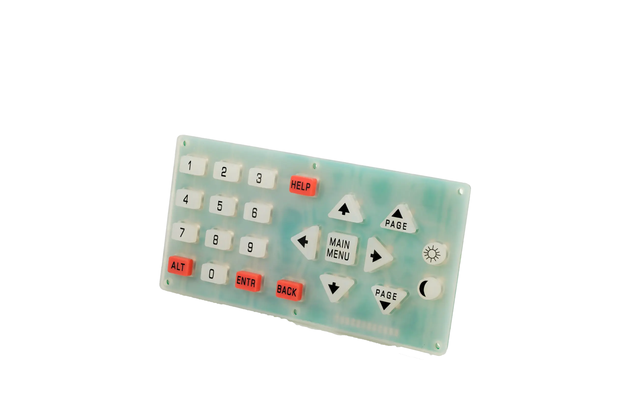
Silicone keypad insert molding is not one universal process. A conductive carbon pill may be preformed, placed in the mold, and co-molded with the keypad. A rigid plastic or metal part may instead be overmolded with silicone and retained by geometry, chemical adhesion, or both. Other keycaps and inserts may be installed only after the silicone part is cured.
For an OEM drawing or RFQ, the useful question is therefore not simply “Is this insert molded?” It is: What is the insert, when is it introduced, how is it located and retained, which surfaces must bond or remain exposed, and how will the finished interface be verified? If the overall keypad architecture is still open, start with JASPER’s custom silicone rubber keypads family before locking the insert route.
- Define the Insert and the Actual Process Route
- Use a Material–Location–Retention–Process–Validation Checklist
- Carbon pills are a molded contact system, not just a loose component
- Review Hard Keycaps and Rigid Inserts for Compatibility and Retention
- Control Location, Retention and Flash in the Tool
- Check Secondary Bonding or Assembly as a Separate Route
- Validate the Finished Interface After Use and Exposure
- Define Supply Responsibility Before Quotation
Define the Insert and the Actual Process Route
The word insert can describe a carbon contact, hard keycap, metal carrier, decorative part, or internal support. Those parts do not require the same tool or process.
| Route | When the second part/material is introduced | Main control question |
|---|---|---|
| Co-molded conductive pill | Preformed pill is positioned before the main silicone cure | Can the pill stay located and keep its contact face clear? |
| Hard-part insert overmolding | Prefabricated plastic, metal or other hard part is loaded before silicone molding | Is the substrate compatible with the molding and retention method? |
| Two-component molding | Hard part and silicone are molded in linked stages | Can both stages and transfer be controlled as one process? |
| Mechanical interlock | Silicone flows through/around holes, grooves or undercuts | Does the geometry retain the insert under the real load path? |
| Self-bonding or primer-assisted overmold | Surface preparation and material selection create chemical adhesion | Has the exact silicone/substrate pair been verified? |
| Post-mold assembly | Keycap/insert is snapped, pressed or bonded after molding | Can assembly position and retention be inspected repeatedly? |
| Printed conductive contact | Conductive material is printed after molding | This is a secondary printing process, not insert molding. |
Distinguish insert molding from one-machine and two-machine 2K molding, and specify mechanical interlocking separately from chemical bonding. “Overmolded” alone does not tell the toolmaker whether retention depends on geometry, adhesion or both.
Use a Material–Location–Retention–Process–Validation Checklist
The insert drawing should define more than its outside shape. The control plan changes with the component.
| Insert type | Material / surface | Location | Retention | Process controls | Validation focus |
|---|---|---|---|---|---|
| Carbon pill | Approved conductive compound/pill; exposed face kept clean | Center and height relative to keypad datum and PCB pad | Co-molded into the key body; positioned before cure | Pill presence, orientation, loading fixture, flash keep-out | Electrical closure, resistance criterion, travel, overlap and retention on the intended circuit |
| Plastic or hard keycap | Exact resin/grade; cosmetic and bonding surfaces identified | Keycap datum, rotation and top height | Mechanical lock, chemical bond, or post-assembly feature | Drying/cleaning where required, insert seating, molding distortion, edge flash | Position, appearance, pull/peel/torque behavior appropriate to use, environmental exposure |
| Metal/plastic carrier or other insert | Defined substrate, finish/coating and contamination limits | Shared datum to keypad/enclosure | Interlock, self-bonding silicone, primer-assisted bond, fastener or secondary assembly | Surface prep, insert presence, flow around retention features, demolding | Dimensional stability, bond/retention, seal or functional interface after exposure |
Carbon pills are a molded contact system, not just a loose component
Industry keypad manufacturing references describe a common architecture in which preformed carbon-loaded silicone pills are positioned in the mold before the keypad body is cured. The pill then becomes co-molded with the nonconductive silicone.
That does not mean every conductive keypad uses the same route. Conductive ink may be printed after molding, metal domes may be assembled separately, and another design may use a different conductive element. The released drawing should name the contact architecture instead of using “conductive insert” as a catch-all term.
For a co-molded pill, control its material identity, center and orientation, the fixture or nest that holds it before molding, the exposed contact face, and the finished electrical behavior on the specified PCB/FPC/PET contact pattern. A loose-pill resistance result alone does not approve the keypad interface.
Review Hard Keycaps and Rigid Inserts for Compatibility and Retention
A rigid insert can be retained mechanically, chemically or by both methods. Overmolding openings or undercuts provides mechanical interlocking. Adhesion routes include self-adhesive silicone, primer-treated substrates, bonding premolded parts and appropriate surface treatment; select the mechanism deliberately.
Before tool release, answer these questions:
- What is the exact hard substrate and grade?
- Which surfaces must bond, and which must remain cosmetic, optical, conductive or free-moving?
- Does the part include holes, grooves, undercuts or other mechanical-retention features?
- Must the interface seal, or is it only structural/cosmetic?
- Can the substrate tolerate the molding and cure conditions without warping or softening?
- Does it require drying, cleaning, plasma/corona/flame treatment, primer, or another controlled preparation?
- Can the insert be loaded in only one orientation, or does the fixture need anti-rotation/poka-yoke features?
Dry thermoplastic inserts as required before overmolding. Difficult combinations may need flame, corona or plasma treatment, and self-adhesive silicone still requires substrate compatibility checks. Specific self-adhesive LIMS systems list materials such as PC, PBT and PA; that does not establish compatibility with every grade. Self-bonding is substrate-specific, not universal.
Non-self-bonding material may need a primer or subsequent adhesive process. LIM6045, for example, usually requires primer when insert molding needs chemical bonding to non-silicone surfaces. Cleaning, primers, surface-energy treatment and roughening are possible adhesion-improvement routes. Qualify the selected material/substrate/process combination rather than treating these options as a fixed production recipe.
Control Location, Retention and Flash in the Tool
An insert can be made from the correct material and still fail because it moved, rotated, floated, warped or became partially covered during molding.
Define the insert datum, allowed position/rotation, seating surface, loading fixture, presence check, flow path, flash keep-out, demolding direction and traceability method. For carbon contacts, silicone flash on the working face can change the electrical interface. For hard keycaps, excess silicone at an exposed edge can create a visible line or rubbing condition. For a mechanical interlock, incomplete fill around the retention feature can reduce effective locking area even when the outside looks acceptable.
These controls should sit beside the other tooling and first-article gates in JASPER’s silicone keypad tooling and prototype guide.
Check Secondary Bonding or Assembly as a Separate Route
If the keycap, insert or carrier is installed after molding, call it secondary assembly or bonding, not insert molding. A post-mold process may need controlled surface preparation, primer/adhesive selection, bondline or engagement depth, fixture orientation, cure/dwell conditions, squeeze-out limits, rework rules and retention inspection.
A post-installed hard keycap may simplify molding or allow late cosmetic variants, but it adds another controlled operation. An overmolded cap can reduce assembly steps, but it increases tooling and material-compatibility demands. Neither route is automatically better.
If purchasing wants rubber, circuit, inserts, LEDs, connector and final test under one supplied boundary, review the silicone keypad assemblies route and state which insert-related operations are included.
Validate the Finished Interface After Use and Exposure
Test the completed interface, not only the incoming insert.
| Validation area | What to verify |
|---|---|
| Material and traceability | Correct silicone, insert, surface treatment and controlled revisions |
| Position | Insert center, height, rotation and exposed area relative to datums |
| Retention | Pull, peel, push-out, torque or flex behavior appropriate to the real load direction |
| Carbon contact | Electrical closure, defined resistance criterion, travel and pad overlap on the intended circuit |
| Visual / flash | No unacceptable flash, contamination, edge lift, sink or exposed bondline |
| Environmental exposure | Interface remains functional after agreed temperature, humidity, cleaners, oils, UV or other relevant exposure |
| Repeated use | Insert does not shift, loosen, delaminate or change the functional interface through the agreed duty |
Do not invent a universal pull force, peel strength, cycle count, temperature or environmental limit. The correct acceptance plan depends on geometry, material pair, load path and product requirement.
Define Supply Responsibility Before Quotation
The RFQ should state who owns the insert drawing, who buys and inspects the insert, who performs drying/cleaning/pretreatment, who loads it into the mold, who performs secondary assembly, and which party approves the final interface. It should also define what changes require requalification.
For an engineering review, send the keypad 2D/3D files, cross-sections through each insert type, mating PCB/contact layout, insert material/drawing, expected quantity, environment, key force/travel targets, cosmetic requirements and intended supply boundary. Unknown items can be marked TBD rather than guessed.
Request a keypad engineering review.
Frequently Asked Questions
Are carbon pills always insert molded into silicone keypads?
No. A common route uses preformed conductive pills positioned in the mold and co-molded with the keypad body, but conductive ink and separately assembled contact systems also exist. Specify the actual contact route.
Can a self-bonding LSR be overmolded onto any plastic keycap?
No. Supplier compatibility lists are material-specific, and the actual resin grade, moisture, additives, surface condition and molding history can change adhesion. Verify the exact combination.
Is a mechanical interlock enough without chemical adhesion?
It can be, depending on geometry, load direction and sealing needs. Validate the real pull, peel, torque and flex conditions. Some designs use mechanical and chemical retention together.
Should a hard keycap be overmolded or assembled after molding?
Overmolding integrates the interface but requires compatible materials and insert handling. Post-mold assembly may simplify the mold or support cosmetic variants, but adds a separate positioning/bonding process and inspection step.
What insert information belongs in the RFQ?
Provide insert material and drawing, required exposed surfaces, location, retention concept, target process route, mating PCB/enclosure geometry, environment, validation requirements, prototype/annual quantities, and the expected supply responsibility for each insert.
Ready to Start Your Project?
Tell us about your membrane switch, keypad, or graphic overlay requirements. Our engineering team will review your specifications and provide a detailed quote.