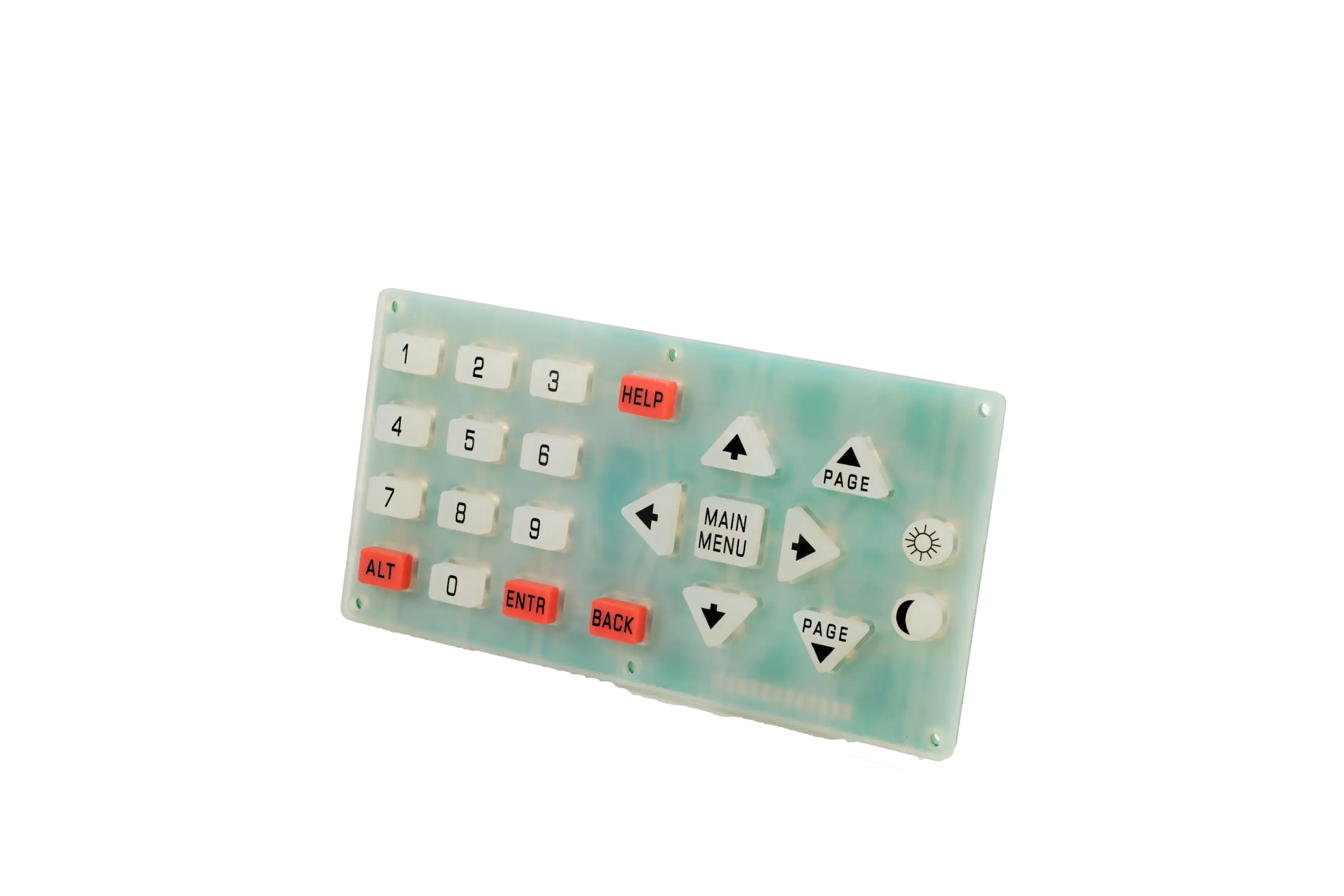
P+R and all-silicone keypads can both provide raised keys over an electronic switching system, but they solve the user-surface problem differently. A P+R construction places a rigid plastic keycap over a rubber key structure or rubber carrier, while an all-silicone construction uses molded silicone as the visible keytop as well as the flexible spring or actuator structure.
The practical choice is therefore not simply “plastic looks premium” versus “rubber is flexible.” The two architectures create different interfaces for key guidance, graphics, backlighting, secondary assembly, tolerance control and sample approval. The right choice depends on the complete finger-to-circuit stack and on how the keypad will be built into the enclosure.
JASPER’s current silicone keypad capability brochure lists P+R keypads as a product category and shows a P+R button process flow that includes assembly. Exact keycap material, retention or bonding method, decoration process and validation scope should still be confirmed for the specific drawing and use environment.
For the broader force-path and molded-key design framework, see JASPER’s Silicone Rubber Keypad Design Guide.
- Define Plastic-Plus-Rubber and All-Silicone Constructions
- What is a P+R keypad?
- What is an all-silicone keypad?
- Quick comparison
- Compare Surface Feel and Key Guidance
- Review Graphics and Backlight Paths
- P+R graphic routes
- All-silicone graphic routes
- Backlight comparison
- Compare Tooling and Secondary Assembly
- P+R adds an interface that must be controlled
- Not every P+R keypad is glued
- All-silicone is not “no secondary process”
- Select Samples for Fit and Finish Approval
- Suggested validation matrix
- How to Choose Between P+R and All-Silicone
- Discuss Your Interface Requirements
Define Plastic-Plus-Rubber and All-Silicone Constructions
What is a P+R keypad?
In this article, P+R means a keypad in which a rigid plastic keycap or key cover is combined with a silicone-rubber key structure. Industry manufacturing references use “P+R keypad” or “plastic-and-rubber keypad” for this type of construction and show the plastic and silicone parts being produced separately and then assembled, often with a bonding or retention step.
The plastic cap is the visible finger-contact surface. Beneath it, the silicone may provide the web spring, return force, sealing feature, light-control geometry or actuator that closes a carbon contact, presses a metal dome, or operates another switch.
P+R is not a synonym for every type of overmolding. Hard-soft joining can use mechanical interlocking, self-adhesive silicone, primer-assisted bonding or bonding of premolded parts. The production drawing must state how the plastic and silicone are retained.
What is an all-silicone keypad?
An all-silicone keypad uses molded silicone for the visible keytop, flexible web and base keymat. The part may still include conductive pills, printed or coated graphics, laser-opened legends, light-blocking layers or other secondary operations. “All-silicone” describes the keycap structure, not the entire electronic assembly.
Silicone can be supplied in transparent, translucent or pigmented systems. Material suppliers also document that silicone properties such as flex fatigue, tear strength and compression behavior depend on the selected compound and test condition rather than on the material name alone. That is why the molded part and the installed keypad should be validated separately.
Quick comparison
| Decision area | P+R: plastic keycap + silicone | All-silicone |
|---|---|---|
| Finger-contact surface | Rigid plastic cap | Molded elastomer surface |
| Key guidance | Can use cap geometry, housing guides and rubber features together | Mainly controlled by molded key geometry, web and housing clearance |
| Force path | Adds a cap-to-rubber interface before the spring/contact system | Load enters the molded silicone key directly |
| Graphics | Plastic printing, coating, laser-opened or molded graphics may be considered | Printed, molded-color, coated and laser-etched silicone routes may be considered |
| Backlight | Plastic cap and rubber layer must be designed as one optical stack | Translucent silicone, opaque coating and laser-opened legends can form the optical stack |
| Tooling / process | Plastic tooling plus rubber tooling and a joining/assembly route are commonly involved | Rubber tooling plus required decoration / secondary processing |
| Main approval risk | Cap retention, alignment, gap, wobble, bond/retention and cosmetic match | Molded geometry, web behavior, coating/legend and installed fit |
| Best reason to choose | A defined rigid key surface or plastic-specific appearance/function is required | A continuous molded elastomer key surface and simpler part interface are preferred |
The table is a design comparison, not a universal cost or life ranking. Tooling method, production volume, decoration, tolerance and assembly scope can change the economics of either route.
Compare Surface Feel and Key Guidance
A rigid keycap changes what the finger touches, but it does not automatically define the tactile response. The press force still travels through the cap, its retention interface, the rubber structure and the switching element.
For an all-silicone key, the operator presses directly on the molded elastomer keytop. Web thickness, key area, travel, contact height, hard stops, preload and enclosure support can all change the press-and-release curve. JASPER’s design guide therefore treats key feel as a measured force-displacement curve rather than as a rubber-hardness label.
For P+R, add three more questions:
-
How is the cap guided?
A large or tall plastic cap may need controlled clearance to the housing or a molded locating feature in the rubber. Too much clearance can create visible wobble. Too little can create side rubbing or slow return. -
How is off-center loading transferred?
A rigid cap can spread a finger load, but the rubber web or actuator underneath still needs to remain aligned with the contact or switch. Check corner presses as well as center presses. -
Where does the tactile event come from? It may come from the silicone web, a metal dome, a tact switch or a combination. In a plunger-operated tact switch, the keytop or plunger transfers finger force to the contact dome; it is not the contact dome itself. Do not credit a plastic keycap with a crisper feel unless the assembled force curve proves it.
For either architecture, approve the key in the real housing with the intended PCB, support, fasteners and hard stops. A loose sample can hide preload, guide interference and contact-alignment problems.

Review Graphics and Backlight Paths
Both architectures can support professional graphics and illuminated controls, but they use different surfaces.
P+R graphic routes
A rigid plastic keycap may support:
- printed legends;
- painted or coated surfaces with laser-opened symbols;
- graphics protected on a rear or internal surface where the cap geometry allows it;
- molded or multi-material legend concepts; and
- different gloss or texture zones produced by the plastic tool and finish process.
These are process options, not automatic durability guarantees. The actual resin, coating, ink, cleaner exposure, abrasion method and viewing requirement must be defined and tested.
All-silicone graphic routes
A molded silicone key can use:
- molded base color;
- pad- or screen-printed legends;
- opaque coatings over translucent silicone;
- laser-etched openings for illuminated symbols;
- protective surface coatings where required; and
- molded light-control walls or geometry.
Silicone can be formulated for high transparency or colored with pigments. Finished keypad appearance still depends on the compound, pigment, coating, wall thickness, LED location and enclosure.
Backlight comparison
| Backlight question | P+R | All-silicone |
|---|---|---|
| Where is the visible symbol formed? | In or on the plastic cap, or through a coordinated cap/rubber stack | In the silicone color/coating/laser system |
| What must be aligned? | Cap artwork, cap retention, rubber opening/light path, LED and housing | Key geometry, coating/laser artwork, LED and housing |
| Common visual risks to inspect | Cap-to-cap color variation, halo at cap edge, internal reflection, misregistration, light leakage | Hot spots, pinholes, cross-talk, uneven coating, laser-edge variation |
| Approval condition | Decorated, assembled and powered sample | Decorated, assembled and powered sample |
Do not approve backlighting from an unpowered cosmetic sample. Use the intended LED and PCB revision, define the viewing angle and ambient condition, and record both lit and unlit appearance.
Compare Tooling and Secondary Assembly
P+R adds an interface that must be controlled
A typical P+R project has at least two formed components: the plastic cap and the silicone key structure. The project may therefore involve plastic and rubber tooling plus a secondary assembly or a multi-material joining process.
That additional interface can create design work around:
- cap position and rotational control;
- bond or retention area;
- assembly fixture and datum;
- adhesive or surface-treatment compatibility when bonding is used;
- cap gap, flushness and height;
- cosmetic damage during assembly;
- rework policy; and
- traceability of cap, rubber and assembled revision.
This does not mean P+R is always more expensive or always slower. It means the quotation must make the tooling and assembly boundary explicit so two suppliers are not being compared on different scopes.
Not every P+R keypad is glued
Distinguish mechanical interlocking from chemical bonding when specifying the hard-soft joint. Chemical-bonding routes also differ. Identify the actual retention and bonding route on the keypad drawing rather than relying on the label P+R.
If adhesive bonding is proposed, confirm:
- the plastic resin and silicone compound;
- surface condition and any pretreatment;
- bondline location and thickness control;
- cure/fixture method;
- contamination controls;
- pull/peel or functional retention acceptance where relevant;
- environmental and cleaner exposure; and
- what happens if the cap must be serviced or reworked.
If mechanical retention or a molded hard-soft construction is used instead, validate the corresponding geometry, insertion load, retention and aging risks.
All-silicone is not “no secondary process”
An all-silicone keypad may still require printing, coating, laser etching, conductive inserts, inspection, trimming and assembly to a PCB or FPC. The key difference is that the visible keytop and rubber spring structure are not joined as two separate cap materials.
If purchasing wants a tested module rather than a loose keymat, review the silicone keypad assemblies scope so the circuit, LEDs, connector, spacer, adhesive and housing interface are included in the same stack review.
Select Samples for Fit and Finish Approval
A useful sample plan separates what each stage is allowed to approve.
| Sample stage | What it can answer | Do not approve yet |
|---|---|---|
| Layout / appearance mock-up | Key size, spacing, finger reach, keycap styling, visual hierarchy | Production rubber feel, final bond, production finish or lifetime |
| Molded rubber sample | Web behavior, key position, return, contact/actuator alignment | Final P+R cap retention, final graphics or powered backlight |
| P+R assembled engineering sample | Cap fit, gap, wobble, retention concept, force path, appearance | Production repeatability unless the process and revisions are controlled |
| Decorated powered assembly | Lit/unlit graphics, cosmetic match, contact function, installed feel | Long-term environment and lifecycle unless those tests are completed |
| Production-representative build | Released materials, tooling, assembly sequence and validation evidence | Untested future changes |
For an all-silicone route, the same logic applies, but the P+R-specific cap-retention step is replaced by molded-surface and decoration approval.
Suggested validation matrix
| Validation area | P+R-specific focus | All-silicone focus | Evidence to retain |
|---|---|---|---|
| Fit and location | Cap height, gap, flush, rotational position, key-to-housing clearance | Key height, guide clearance, molded position | Dimensional report + installed photos |
| Force and travel | Complete cap-rubber-switch stack, center and off-center press | Complete molded key and switch stack | Press/release force-displacement curves |
| Return / sticking | Cap rubbing, retention shift, rubber preload | Web return, coating rub, housing preload | Repeat test in installed housing |
| Retention / bond | Pull-off, peel, insertion or functional retention as applicable | Not applicable to a separate cap; inspect molded integrity | Defined method and sample revision |
| Electrical switching | Contact alignment and switch point through the cap/rubber stack | Contact alignment and switch point | Closure result tied to force/travel |
| Graphics | Cap print/coating/laser alignment and wear | Silicone print/coating/laser condition | Approved visual standard + process test |
| Backlight | Cap/rubber/LED optical alignment | Silicone/LED optical alignment | Powered photos and defined viewing condition |
| Environment | Bond/retention, plastic finish, rubber and enclosure interaction | Rubber/coating/enclosure interaction | Project-specific exposure record |
| Lifecycle | Cap motion plus rubber/switch behavior | Rubber/switch behavior | Cycle method, failure criteria and sample ID |
No universal cycle count, pull force, abrasion load or tolerance is assigned here. Those acceptance values should come from the product requirement and the agreed validation plan.
How to Choose Between P+R and All-Silicone
Choose P+R for review when the rigid keycap itself solves a defined requirement—for example, a plastic-specific surface geometry, a distinct hard touch surface, a particular graphic construction, or a mechanical relationship to the housing that is difficult to create with a soft molded keytop alone.
Choose all-silicone for review when the design benefits from a continuous molded elastomer surface and you do not need a separate rigid cap to meet the appearance, guidance or graphic requirement.
In both cases, treat the decision as an assembly choice rather than a styling choice. Compare the two routes using the same:
- enclosure and PCB revisions;
- key map and ergonomic requirement;
- target force and travel behavior;
- graphics and backlight requirement;
- cleaning and environment;
- prototype quantity and annual volume;
- validation plan; and
- supplied assembly boundary.
That creates a meaningful quotation comparison and prevents one option from looking cheaper only because it excludes tooling, decoration, assembly or validation work that the other option includes.
Frequently Asked Questions
Is a P+R keypad always more durable than an all-silicone keypad?
No. A rigid plastic cap changes the wear surface, but the finished life still depends on the resin, coating or legend process, cap retention, rubber web, switch/contact system, environment and test method. Compare production-intent samples under the same acceptance plan.
Does a plastic keycap automatically make the button feel crisper?
No. The tactile event may come from the silicone web, a metal dome, a tact switch or a combination. The cap changes the finger interface and load path, but the installed force-displacement curve is the better approval measure.
Can P+R keypads be backlit?
Yes, when the plastic cap, rubber structure, coatings or legends, LED position and light-blocking features are designed as one optical stack. Approve a powered sample rather than assuming a transparent component will create acceptable illumination.
Does every P+R keypad require adhesive?
No. Hard-soft assemblies can use different retention or bonding concepts. The production drawing and quotation should state whether the project uses adhesive, mechanical retention, a molded multi-material process or another controlled method.
Which route is easier for an early prototype?
A simple all-silicone architecture can have fewer cap-to-rubber interfaces, but prototype effort depends on the actual geometry and surface requirement. A machined or 3D-printed plastic cap can help review size and appearance, but it does not approve production molding, bond strength, production finish or lifecycle behavior.
Discuss Your Interface Requirements
For an engineering review, send the information that defines the complete keypad rather than only a keycap image:
- 2D drawing and 3D model, if available;
- existing keypad or product sample photos;
- enclosure section and PCB/contact layout;
- key count, spacing, keytop shape and critical cosmetic gaps;
- target press/release feel and travel;
- contact architecture: carbon pill, metal dome, tact switch or TBD;
- legend, color, texture and backlight requirements;
- cleaning agents, oils, UV, temperature or other exposure that matters to the product;
- prototype quantity and expected production volume;
- supplied boundary: loose keypad, decorated keypad or tested assembly; and
- any open decision marked TBD.
Review custom silicone rubber keypads for the broader molded-keypad options, or request a keypad engineering review with the drawing and the requirements that are already known.
Ready to Start Your Project?
Tell us about your membrane switch, keypad, or graphic overlay requirements. Our engineering team will review your specifications and provide a detailed quote.