A capacitive touch HVAC control panel should be specified as an input sequence, not just illuminated icons. For a wall-mounted thermostat, decide whether the first touch only wakes the interface, how taps and holds adjust the setpoint, and when the display confirms host acceptance. Validate those rules in the installed enclosure and each intended power configuration.
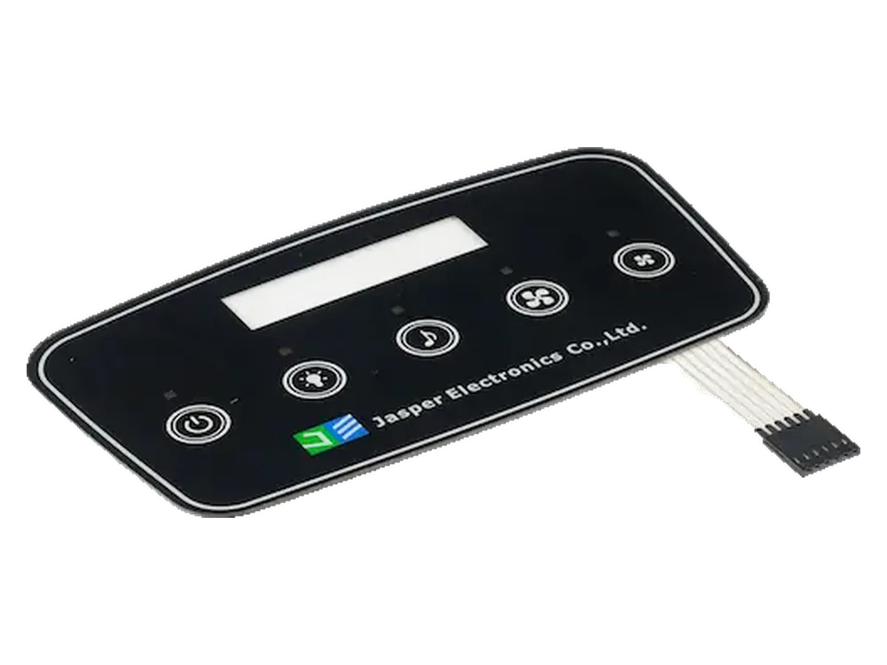
This guide covers fixed-function buttons beside a display, not coordinate-based PCAP touchscreen testing, temperature-control algorithms, or networking. It is not a complete thermostat offer. For the physical interface, review custom capacitive touch panels with an explicit boundary between the supplied front panel and the thermostat electronics.
Define Setpoint and Mode-Selection Tasks
Define what constitutes one accepted command before freezing the key layout. An Up/Down/Mode/Fan arrangement needs more than electrode positions: specify units, adjustment increments, permitted limits, mode order, disabled functions, and feedback for rejected requests.
Choose whether commands occur on press or release. Assign hold repetition to either the touch firmware or the host, not both. Record the hold delay, repeat interval, and release-to-stop requirement. A continuously reported “pressed” state must not become a new command on every host poll.
Separate responsibilities: the cover provides the visible and dielectric surface; the sensor defines sensing zones; the controller measures touch; touch firmware qualifies press/release events; the display presents feedback; the host accepts setpoints and owns thermostat operation. Name the owner of each in the quotation.
The illustrative workflow below executes on qualified presses, uses host-owned repetition for Up/Down, and submits edits immediately for host validation. “Accepted” means accepted by host application logic, not merely acknowledged on a communication bus.
Coordinate Touch Targets and Display Windows
Keep the target being touched and the value being adjusted visually unambiguous. Dimension the display window, printed icons, and electrode targets separately. Use the custom capacitive touch panel design guide for the complete drawing package; add a thermostat-specific view showing finger positions beside the displayed setpoint and mode.
Review a full-size mockup at the intended wall height and viewing angles. Check whether a finger obscures the number, whether the window can be mistaken for a button, and whether Up and Down remain distinguishable when dimmed. Record permitted registration variation and the regions that must not issue commands.
For a backlit thermostat touch interface, compare unlit, night-dimmed, and active appearances. Mark display illumination and key illumination separately: lighting the window does not automatically make hidden key symbols discoverable.
Plan Standby, Wake and Lighting Behavior
Choose wake-only or wake-and-act explicitly. Here, standby describes the user interface; it does not instruct HVAC equipment to stop. Wake-only consumes the first contact without changing a setting. Wake-and-act lets a qualified first contact execute once; the transition into active scanning must not count that contact again. Document when any hold timer starts. Use the readiness-and-release gate again after restart.
Illustrative state map: wake-only, immediate host-approved edits, and no automatic repetition for Mode/Fan. This is a requirements example, not a tested JASPER implementation.
| Operating state | Touch event | Display and backlight | Host response and next state |
|---|---|---|---|
| Standby | No touch | Agreed off or dimmed appearance | No edits; configured wake sensing remains available |
| Standby → Waking | First qualified key press | Illuminate; show current accepted settings | Consume the contact as wake-only; issue no setting command |
| Waking | Held contact or additional touches before readiness | Present settings and readiness feedback | Discard command input until host, scanning, and feedback are ready and all keys are released |
| Ready → Adjusting | Fresh Up/Down press | Show the host-accepted value | Submit one step request; apply only if permitted |
| Adjusting | Continued hold, then release | Track accepted values; indicate limits | Repeat within limits after the agreed delay; release cancels repetition and returns to Ready |
| Ready | Fresh Mode/Fan press, then hold | Show accepted selection or rejection | Process once; do not repeat while held |
| Ready → Standby | Inactivity timeout with all keys released | Return to standby appearance | Retain accepted settings; leave no deferred edit or repeat |
Choosing the scan rate involves a tradeoff between power consumption and response time. Switching LEDs between driven and high-impedance states can also change capacitance and cause false detection. Evaluate these effects for the selected controller; they are design considerations, not universal performance guarantees.
Test lighting transitions without a hand present, then during tapping and release. Record unintended events, wake latency, accepted-command feedback latency, scan configuration, and LED-drive conditions. Do not define “standby” solely by whether the backlight is off.
Review Enclosure Mounting and Power Conditions
Approve the interface in its installed electrical and mechanical configuration. A thermostat reference implementation with discrete capacitive buttons and LED indicators uses separate battery-powered and line-powered modes. Its measurements apply to that implementation, not to a custom panel with different hardware.
Ground-to-earth coupling depends on the application and power system. In a self-capacitance sensing model, a weak return path can reduce the touch signal. Compare the intended supply and mounting configuration rather than assuming a bench connection represents installation.
Include the actual wall plate, approved backbox and fasteners, wiring route, cover support, and display. Repeat checks with diagnostic cables removed where practical, documenting any test connection that changes the electrical reference. Do not modify protective earthing or isolation to improve touch response.
Exercise startup, permitted supply variation, and brownout recovery. Measure complete-device consumption in standby, wake, sustained adjustment, and lighting transitions across the specified supply conditions. Record the measurement boundary and operating durations before estimating energy use or battery life.
For a combined front stack, review HMI assembly requirements alongside the enclosure drawing. Specify separately who supplies the display, controller, firmware, and installed-system validation.
Validate Inputs across the Operating State Map
Compare the accepted command history with the intended input history—not just whether an icon lights. Set the valid tap duration and gap, repeat timing, feedback deadline, and release-to-stop limit before testing. Use project-defined setpoint limits and increments, not borrowed benchmark numbers.
Illustrative boundary and repetition test template. Actual-result cells are intentionally blank for measured findings.
| Test condition | Input sequence | Expected result for this concept | Actual result |
|---|---|---|---|
| Single adjustment | Valid Up tap, release, then Down tap | One accepted step per press; correct final display | |
| Rapid burst | Counted valid taps away from a limit | Matching ordered command count; no loss or duplication | |
| Direction reversal | Alternate Up and Down rapidly | Correct order; no inherited repeat in the previous direction | |
| Wake-only hold | Hold the first standby contact through wake | No adjustment until release and a fresh press after readiness | |
| Upper and lower limits | Tap and hold toward each limit; then reverse | Clamp without wraparound; no stored excess inputs delaying reversal | |
| Release near repeat deadline | Release around a scheduled repeat | No repeat after host processes release; physical release-to-stop meets the agreed limit | |
| Mode/Fan hold | Press and keep touching | One selection request; no automatic cycling | |
| Overlapping keys | Simultaneous and staggered Up/Down contacts | Stop further adjustment once overlap is recognized; rearm after all keys release | |
| Sleep boundary | Press around the inactivity deadline | Apply the documented ordering: active command or wake-only, never both | |
| Power recovery | Interrupt and restore power with a key touched | Cancel stale input; issue no startup touch command; apply host recovery rules | |
| Non-target contact | Touch the display window and between icons | No mapped setting command |
Run the relevant rows with each approved lighting, supply, mounting, and environmental configuration. Include no-touch observation during transitions.
Correlate physical contact timing, controller press/release, host acceptance, and display response. Keep sample IDs, drawing and firmware revisions, controller configuration, supply conditions, installation details, and trace references with each result. This separates sensing failures from event-handling and display failures.
Frequently Asked Questions
Use these questions to close remaining requirements before prototype approval.
Can one front panel serve battery-powered and externally powered variants?
Treat them as separate validation configurations. Reuse the front geometry only after checking each variant with its actual power source, grounding, scan configuration, display, and lighting. Keep separate configuration records where the electrical conditions differ.
How should scheduled changes interact with manual adjustment?
Specify which host rule takes priority: the schedule, a temporary override, or a confirmed manual setting. Test a scheduled change during rapid tapping and holding. Display the accepted target and override status without replaying obsolete input.
What about separate heating and cooling setpoints in Auto mode?
Have the thermostat system owner define the permitted pair of values and any required separation. Test adjustments near both constraints and show which value is being edited. Do not invent a universal temperature gap in the panel specification.
Can room temperature and the edited setpoint share one display area?
Yes, provided the interface clearly identifies the value currently shown. Specify labels, transition timing, and the return to room-temperature display. Verify that a user can confirm the accepted setpoint before the display changes context.
What should happen during cleaning?
Specify an input-inhibit mode and its entry and exit rules. While inhibited, wiping must not change setpoints or modes. Test release and recovery before restoring normal inputs; do not treat illumination during wiping as permission to execute commands.
Should an illuminated Heat icon mean that heating equipment is running?
Only when the icon is explicitly assigned to an equipment-running status supplied by the host. Keep selected mode, accepted setpoint, and actual output status distinct. Ordinary touch keys and indicators must not replace required equipment-protection functions.
What must be rechecked after a display or firmware replacement?
Repeat wake, lighting-transition, rapid-input, release, and power-recovery tests with the changed part or revision. Confirm that the event edge, repetition owner, display acknowledgment, and startup policy still match the approved specification.
Prepare an HVAC Interface Review Package
Submit the layout together with the behavior it must support. Include the dimensioned front and display-window drawings, cover stack, key map, wake policy, repeat rules, lighting states, wall-mount details, power configurations, controller/host boundary, validation requirements, prototype quantity, and expected production volume.
Review My HVAC Interface Layout — send these materials through JASPER’s RFQ form so the requested physical assembly and acceptance scope can be identified.
Ready to Start Your Project?
Tell us about your membrane switch, keypad, or graphic overlay requirements. Our engineering team will review your specifications and provide a detailed quote.