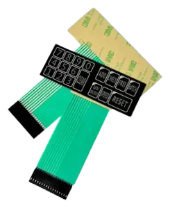
Electrical inspection of a membrane switch circuit. Qualification of service life requires a separate, defined test plan.
A membrane switch lifespan claim is meaningful only when it identifies what was tested, how it was operated, and what counted as failure. A metal dome rating, a cycling result from a prototype, and service life in an installed machine are different kinds of evidence. None should be presented as a universal number of years or presses.
On this page
On this page
For OEM projects, the useful question is: Can the specified assembly keep meeting its electrical, mechanical, and user-interface requirements throughout the intended duty profile?
For custom membrane switch assemblies, define the test boundary first: overlay, switching layers, tactile element where used, spacers, bonds, circuit tail, connector, and representative enclosure support. Identify any lighting or sealing functions included in the durability requirement.
What does a membrane switch life rating actually describe?
When comparing membrane switch actuation life, separate component ratings, test results, product validation, field experience, and warranty terms. Treating them as interchangeable makes supplier comparisons unreliable.
| Evidence | What it can establish | What it does not establish by itself |
|---|---|---|
| Component rating | Performance of a named dome or material under the supplier’s stated conditions. | Life of the laminated switch, installed keypad, or machine. |
| Sample cycling result | What identified specimens completed in a recorded setup, with stated measurements. | Qualification of every production unit or an untested construction. |
| Finished-assembly validation | Whether representative finished assemblies met an approved acceptance plan. | Unlimited applicability to different mounting, environments, electrical loads, or revisions. |
| In-service evidence | Observed performance of a defined equipment population with a known exposure history. | A universal life claim without information about use, failures, replacements, and units still operating. |
| Warranty period | The coverage period and conditions stated in the supply agreement. | An engineering prediction of when a switch will fail. |
A component test can be narrower than its headline suggests. Snaptron’s published test procedures describe a dome mechanical-cycle test that excludes electrical-resistance testing and defines failure as dome cracking before the specified rating. That is useful component evidence—not proof that every electrical function of a finished keypad remained acceptable.
Material data need the same caution. The Autotex product data sheet, dated 12 April 2022, states that its laboratory-sample results are general guidance rather than the properties of the final product.
What changes membrane keypad durability after assembly?
The installed stack changes how the operator’s load reaches the switching contact. Review the following mechanisms rather than assuming that a higher component cycle rating solves every durability risk.

Applied force and travel can change the failure mechanism
Specify the load and stroke applied to the assembled key, not just the loose dome’s trip force. Distinguish the force needed to close the contact from the peak load applied after closure.
Excess stroke can damage a dome before ordinary fatigue becomes the limiting issue. Snaptron’s handling guidance warns against pushing most of its domes beyond their designed travel and against actuating them with unevenly supported feet. It also identifies designs specifically intended for overtravel; the selected component drawing therefore matters.
For the test fixture, document the loading direction, maximum force, travel limit, and release motion. Do not apply an arbitrary overload percentage and assume it represents ordinary use.
Press position and local support belong in the test setup
A centered laboratory probe and a finger pressing near a key edge are different loading cases. Actuator size and alignment matter: Snaptron’s actuator guidance describes how an oversized actuator can damage a conventional dome and how some integrated-actuator designs respond differently to misalignment.
Use that distinction to plan the test: identify the intended press area and foreseeable off-center loading, then reproduce the backing and mounting underneath that area. A loose panel on a rigid bench is not automatically representative of a panel spanning an enclosure opening.
Overlay, spacer, and preload need an assembled-key check
Review overlay thickness and forming, spacer openings, adhesive placement, vent paths, and available clearance together. As an engineering check, look for layers that restrict return motion, load the key at rest, or move the contact area away from its intended support.
Assembly preload changes the starting condition. Compare the unpressed and released states after mounting, not only before bonding the switch to the housing. Depending on the structure, interference may appear as altered force, incomplete release, or an unintended closed contact; the direction and size of the change should be measured rather than assumed.
Trapped air is another setup variable: Snaptron’s force-test procedure specifies venting because air under the dome changes the measured force. For a sealed product, review the pressure-equalization route within the intended sealing boundary rather than simply opening a path to the outside.
Use the metal dome engineering reference for component and integration details. The durability decision still belongs to the finished assembly. A non-tactile construction also needs its own verification; removing a metal dome does not remove the need to evaluate the flexible circuit, overlay, and bonds.
Which operating conditions belong in the durability requirement?
Write one duty profile that combines mechanical operation with environmental exposure and electrical use. Separate tests can help isolate causes, but they should not leave important combinations unexamined.
Temperature, humidity, and exposure time. Record operating and storage conditions, duration at the extremes, condensation risk, and relevant sunlight, dust, oil, or water exposure. The Autotex data sheet distinguishes temperature guidance by humidity condition—a useful reminder not to combine separate material limits into an assumed finished-switch rating.
Cleaning. Specify the actual cleaning product, use concentration, contact time, wipe material, wiping action, frequency, and drying or rinsing procedure. A film-level solvent result does not identify the performance of the printed, bonded assembly. As a project-specific check, inspect legends, windows, key areas, edges, and bond lines after the relevant cleaning sequence.
Electrical operation. Record sensing voltage, switched current, load type, contact timing, and the controller’s input-detection and debounce settings. State the measurement path: resistance at the external tail terminals includes more than the local contact interface. A mechanical cycling result should not be relabeled as electrical endurance under an untested load.
Operating frequency and dwell. Record bursts, hold times, full-release intervals, and rest periods as well as total presses. Before increasing the laboratory cycling rate, check whether it still reproduces the intended motion and release. Compressing the press count into a shorter test does not, by itself, reproduce years of moisture exposure, cleaning, or storage.
For a practical combined-exposure assessment, consider a baseline group and a group exposed to the relevant cleaning or environmental sequence before, during, or between cycling blocks. Select the sequence from the equipment’s actual use and the failure mechanism being investigated; do not combine unrelated maximum stresses merely to make the test look severe.
How do you turn equipment use into a verification requirement?
Estimate mechanical actuations per key from the operator’s tasks. Do not divide total keypad activity evenly across all keys unless actual use supports that assumption.
For a repeated task:
Expected actuations per key = presses of that key per task × tasks per shift × shifts per day × operating days per year × planned service years.
Count a physical press-and-release as one mechanical cycle. Record a long hold as dwell time; software-generated repeats while the key remains down are not additional physical press-and-release cycles.
Illustrative example: a frequently used confirmation key
The following figures are invented planning inputs, not JASPER test results, customer data, or recommended universal specifications.
| Planning input | Illustrative assumption |
|---|---|
| Physical presses of the confirmation key per task | 2 |
| Tasks per shift | 80 |
| Shifts per operating day | 2 |
| Operating days per year | 250 |
| Planned equipment service period | 5 years |
| Calculated use for that key | 400,000 actuations |
The calculation is:
2 × 80 × 2 × 250 × 5 = 400,000 actuations.
Now examine uncertainty. If the intended deployment includes 100 tasks per shift rather than 80, the same calculation gives 500,000 actuations. That additional demand comes from a stated use scenario, not an unexplained safety factor. Include setup, retries, maintenance, and other tasks where they add physical presses.
Cleaning needs a separate exposure count. In this same illustrative example, three cleaning events per operating day would produce 3 × 250 × 5 = 3,750 cleaning events. An event must still be defined by the actual cleaning procedure; it is not automatically equivalent to one wipe stroke.
These figures are inputs to the validation plan. They do not establish a five-year warranty, a population failure probability, or proof that a specimen completing the cycle target will survive five calendar years. Choose any additional margin from documented uncertainty and failure consequences, alongside the sample and environmental plan.
What should a finished-switch life-test plan include?
An actionable plan identifies specimens, fixtures, operating conditions, measurements, failure rules, and reporting requirements before cycling starts.
ASTM F1578-24 is the active contact-closure cycling test method. Its published scope covers repeated depression and release to a predetermined count, with optional specified voltage and current. Its significance-and-use section discusses mechanical deterioration and electrical changes, with measurements before, during, and after exposure. It does not turn a selected cycle count into a universal service-life guarantee.
The table below is a proposed project-planning framework, not a completed test record or a reproduction of the standard’s procedure. The laboratory should use the agreed complete method and document any deviations.
| Plan item | What to define and retain |
|---|---|
| Test purpose and boundary | State whether the work is design comparison, finished-assembly qualification, or installed-equipment validation. Identify included switching, lighting, and sealing functions. |
| Samples and traceability | Record the number of complete assemblies, selection rationale, lots, serial identifiers, drawing and bill-of-materials revisions, and production-representative construction. Separate cycling specimens from retained references. |
| Key selection | Identify keys and locations under test, their individual targets, and the reason they represent the intended usage or construction. |
| Mounting and fixture | Use the intended enclosure or a justified equivalent. Record support, bonding procedure and conditioning, clamping, tail routing, connector engagement, and fixture photographs. |
| Actuation conditions | Define probe material and contact shape, press coordinates, direction, force or displacement control, limiting force/stroke, and full-release position. |
| Rate, dwell, and sequence | Specify cycling frequency, pressed and released dwell, bursts, rest periods, total count per key, inspection checkpoints, and the basis for any accelerated rate. |
| Environment and cleaning | Specify conditions, durations, solution identity and concentration, cleaning action, and exposure order. Identify measurements made during exposure versus after recovery. |
| Electrical conditions | Define supply and load, measurement terminals, instrument settings, detection timing, debounce, and how missed closures, unintended inputs, and failed releases are detected. |
| Measurements | Establish a baseline and scheduled checks for closed-path resistance, open-state isolation, force–displacement behavior, release, and relevant visual, bonding, sealing, or lighting performance. |
| Failure criteria | Set approved limits and event rules before testing. Include missed intended input, unintended input, failure to return open, resistance outside limits, force/travel outside the approved envelope, or specified visual/bond/seal failures. |
| Process records | Retain per-specimen counts and results, time-stamped events, environment logs, calibration identification, interruptions, fixture adjustments, deviations, and photographs. Distinguish a fixture fault from a specimen failure without erasing either record. |
| Report and applicability | Report survivors and failures individually, achieved counts, first detected failures, acceptance decisions, and untested conditions. Limit conclusions to the represented construction and conditions. |
Make acceptance criteria usable at the instrument and controller level. Define how a missed input is detected and what the open and closed thresholds mean for the actual circuit. A final continuity check alone cannot show whether intermittent events occurred earlier in the run.
Similarly, specify the acceptable force–travel envelope rather than importing an unexplained percentage of allowable force decay. Include legend readability or lighting performance when those functions are part of the interface requirement, even if the key still closes electrically.
Keep this qualification plan separate from routine membrane switch testing and quality control. Shipment inspection and long-duration qualification answer different questions.

How should you interpret a completed life test?
Interpret the result as evidence about the identified specimens under the recorded conditions—not as an automatic product-family promise.
If testing ends at the planned count without failures, report the achieved count and the fact that no defined failure was observed. Do not report that count as the measured wear-out point: the specimens were not necessarily tested until failure.
Report individual results rather than only an average. If inspections were periodic, distinguish the last confirmed passing checkpoint from the first failing checkpoint. Do not invent an exact failure cycle inside that interval.
A population reliability statement also needs a defined statistical plan, sample selection, and exposure model. Repeated actuations on one specimen are not interchangeable with testing many independent assemblies. A bare statement of “zero failures” is not enough to quantify field reliability.
Keep the report with the released drawings and sample approval documentation. The approval record should make clear which construction and installation the evidence supports.
What should purchasing ask before accepting a durability claim?
Ask for the evidence behind the number, not just a larger number on the quotation. These six questions make a useful supplier review:
- What exactly was tested? Request the assembly revision and distinguish a component report from a finished-switch report.
- Does the setup represent our installation? Ask for mounting and actuator photographs, press coordinates, load, stroke, and support details.
- Which conditions were included? Compare electrical load, cleaning, environment, operating rate, dwell, and exposure sequence with the equipment specification.
- What counted as failure? Request detection rules and limits, not only a cycle counter photograph or a pass label.
- What happened to every specimen? Request individual results, interruptions, deviations, failures, and the basis for applying the results to the proposed production build.
- What is included commercially? Distinguish sample approval, qualification work, report delivery, production inspection, and warranty terms in the quotation.
FAQ: judging finished membrane switch life
Can one tested key represent every key on the panel?
Only with a documented technical justification. Compare key geometry, tactile element, overlay forming, spacer structure, local support, press location, and usage. A center key and an edge key may require separate cases. Define representative groups before using one result to cover other locations.
How should a rarely used but important key be evaluated?
A low press count does not remove the need to verify function after the expected idle, storage, and environmental exposure. Include first-operation and release checks after those conditions. Evaluate any safety-related role through the equipment’s applicable safety assessment, not through cycle count alone.
Can an old report be reused after a design change?
Not solely because the commercial part number stayed the same. Compare the tested and proposed bills of materials, layer dimensions, tooling, assembly process, mounting, electrical conditions, and controller settings. Use a documented change assessment to decide what evidence remains applicable and what needs additional testing.
Send JASPER the use profile—not just a cycle-count target
To discuss a durability requirement, send your membrane switch validation requirements with the drawing revision, key layout, enclosure support, and circuit or pinout.
In the project details, include per-key use estimates, the planned service period, press and hold behavior, operating and storage conditions, the actual cleaning procedure, and electrical sensing conditions. Add your acceptance limits and required report format where available.
Request an agreed scope covering representative specimens, fixture setup, exposure sequence, measurements, failure criteria, and who will perform each evaluation. This creates a basis for reviewing the proposed assembly without treating a component rating as a finished-product guarantee.
Send your project requirements ↗Ready to Start Your Project?
Tell us about your membrane switch, keypad, or graphic overlay requirements. Our engineering team will review your specifications and provide a detailed quote.