A flexible pressure sensor array should be designed from the spatial decision the controller must make, not from an attractive grid of sensing pads. Define what each zone must observe, which loads it must reject, how quickly its data must be available, and what evidence will separate a real event from crosstalk or a channel fault. Then select independent zones, a shared-return layout, a scanned row-column matrix, or a hybrid. Zone geometry, trace routing, electronics, scan order, lamination, calibration, and software interpretation must describe the same physical array.
For an OEM project that needs thin distributed sensing, JASPER’s flexible pressure sensor array page is the commercial route for reviewing a custom membrane-style layout. The quotation still has to confirm the sensing principle, zone count, electrical topology, material stack, tail, connector, calibration boundary, and validation scope. A product photograph or the phrase multi-zone does not prove pressure accuracy, spatial resolution, automotive qualification, or a particular circuit.
Define the Observation Before Drawing the Array
An array exists to answer a spatial question. The question may be simple: did load reach the left or right part of a cushion? It may be more demanding: is an approved pattern present across several regions, or has load shifted outside the expected area? Those are different observation problems even when the outside sensor shape is identical.
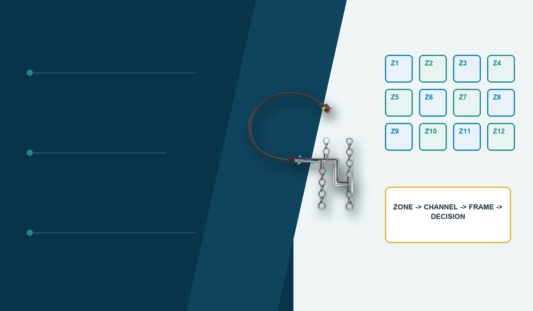
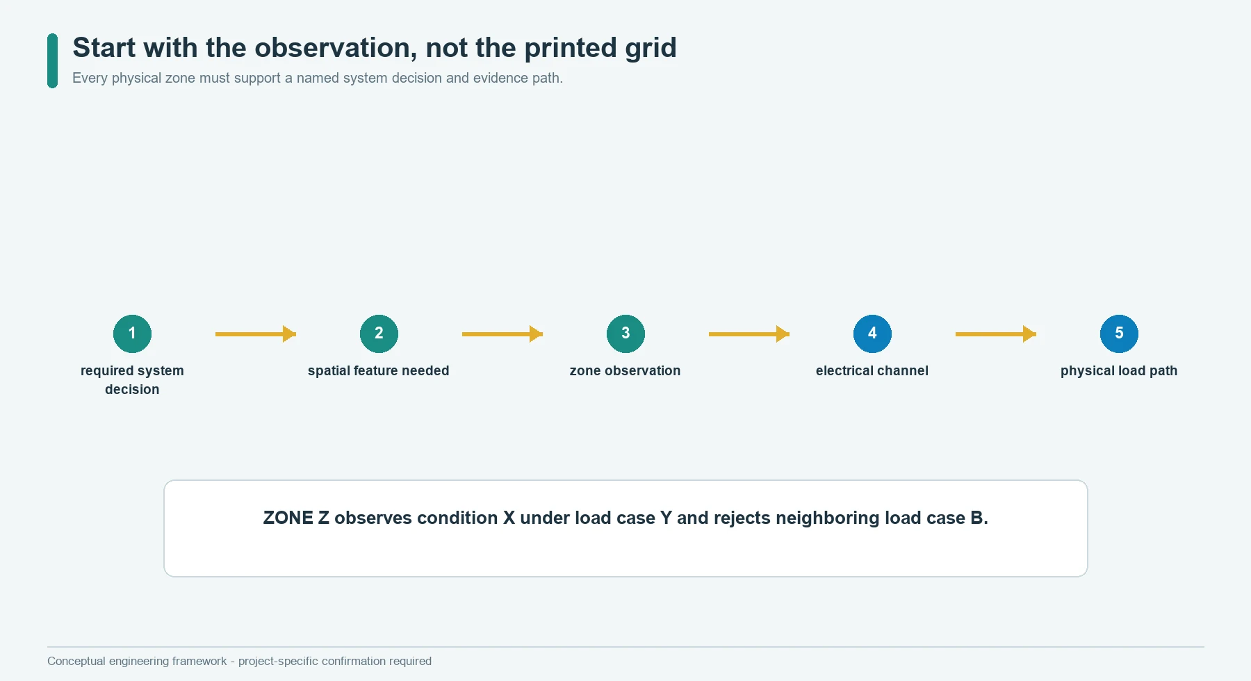
Begin with the final decision and work backward:
required system decision
          |
spatial feature needed for that decision
          |
zone or sensing-element observations
          |
electrical channels and scan frame
          |
physical sensing layout and load path
The design team should be able to complete this statement for every channel:
Zone Z exists to observe condition X under load case Y, while remaining inside acceptance state A when neighboring or prohibited load case B occurs.
If a zone has no such statement, it is not yet an engineering requirement. It is only geometry.
| Required decision | Minimum spatial observation | Unnecessary complication to avoid |
|---|---|---|
| Any approved load is present | One validated coverage zone may be enough | Adding a dense matrix without a location requirement |
| Load is on the left, center, or right | Three zones with controlled effective footprints | Claiming a continuous pressure map from three channels |
| A stable multi-zone pattern is present | Named channel combination plus timing and fault rules | Treating any simultaneous activation as valid |
| Relative load distribution is changing | Comparable channels, controlled mechanics, and a defined normalization method | Reporting uncalibrated raw values as pressure |
| A pressure image is required | A matrix, suitable acquisition system, calibration, and spatial validation | Calling a coarse set of independent pads a mapping instrument |
This backward definition keeps the sensor count proportional to the information the system actually uses.
What a Flexible Pressure Sensor Array Actually Contains
A flexible pressure sensor array is a thin assembly with multiple pressure-responsive regions and an electrical path that lets the connected system distinguish those regions. The regions may be separate contact switches, force-sensitive resistive zones, or another confirmed sensing structure. They may have dedicated conductors or share conductors in a matrix.
Several terms must remain separate:
| Term | Working definition |
|---|---|
| Physical zone | Printed, deposited, assembled, or otherwise formed sensing feature on the flexible stack |
| Effective footprint | Area in the finished assembly where an applied load can influence a zone |
| Channel | Electrical measurement path presented to the electronics |
| Sensing element | Smallest physical feature that the architecture intends to distinguish |
| Array frame | One time-related set of observations used together by the algorithm |
| Spatial resolution | Smallest location difference the complete installed system can distinguish under stated conditions |
| Crosstalk | Response assigned to one observation path because another load, path, sample, or inference influenced it |
| Calibration object | Physical assembly and electronics represented by the approved calibration data |
The physical zone and channel are not always one-to-one. Several elements may share a row or common return. One zone may also be represented by more than one measurement path when diagnostics or redundancy are required.
Tekscan describes pressure mapping systems as arrays of pressure sensors scanned and converted into data for analysis.[2] That establishes a useful system boundary: the flexible sheet is only one part of the array. Electronics, acquisition timing, calibration, and interpretation create the usable spatial record.
Choose Dedicated Zones or a Scanned Matrix
The first topology decision is how physical regions become identifiable electrical observations.
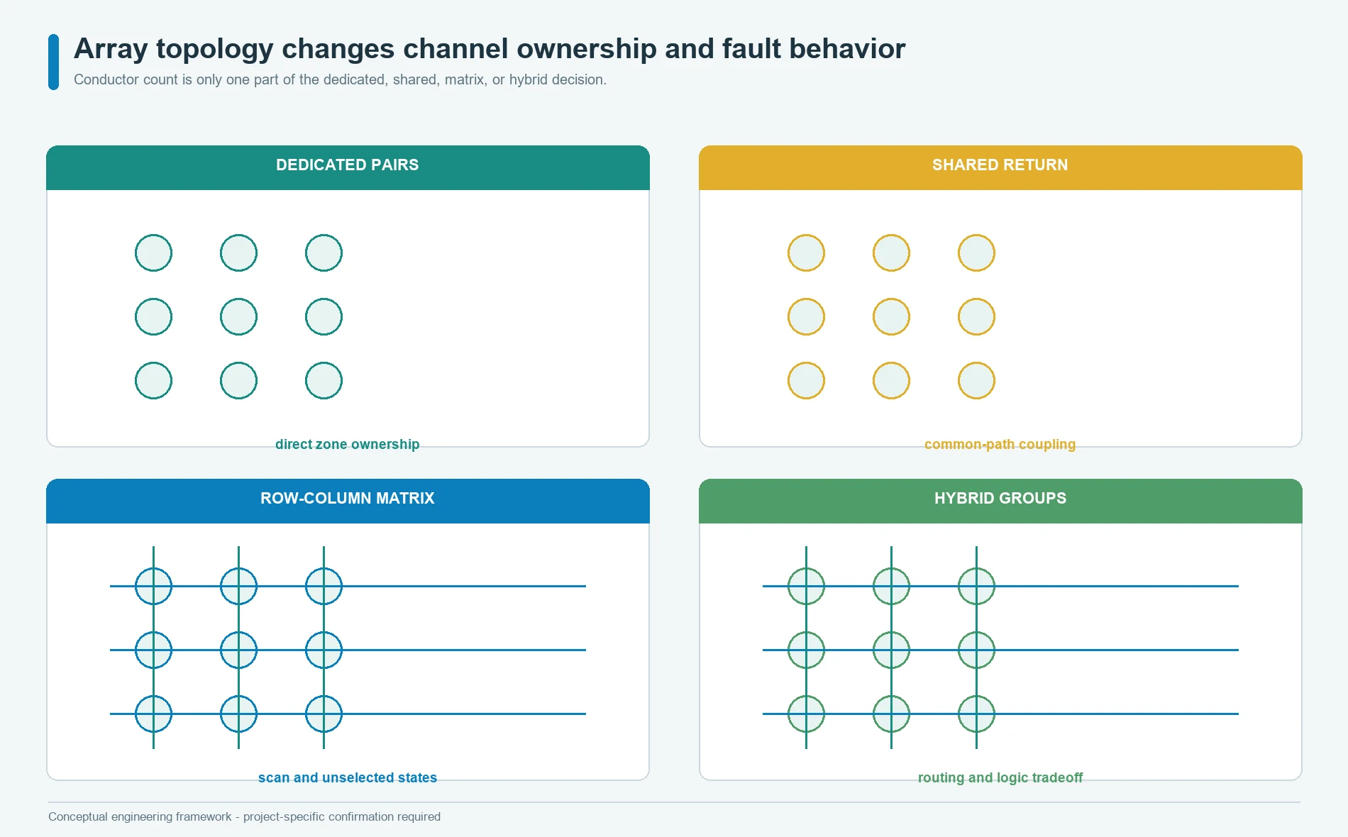
| Architecture | Channel identity | Main benefit | Main cost or risk |
|---|---|---|---|
| Dedicated two-wire zone | Each zone owns its complete pair | Direct fault and signal ownership | Tail width, conductor count, connector pins, and electronics grow with zones |
| Dedicated zone with shared return | Each zone has one unique path and one common path | Fewer conductors than isolated pairs | Shared resistance, leakage, or damage can affect several zones |
| Row-column matrix | Elements are selected through row and column conductors | Many physical intersections can be addressed with fewer external conductors | Scan timing, unselected paths, channel memory, and fault isolation become harder |
| Hybrid groups | Small local matrix or shared group feeds dedicated higher-level channels | Can balance routing and information needs | More topology states and documentation are required |
A dedicated-zone array is often easier to reason about because a channel has a clear physical owner. That does not make it automatically better. A large number of zones can make the body-to-tail transition and connector impractical.
A row-column matrix reduces external conductor count by sharing addressing paths. The acquisition system selects rows and columns in sequence, so the final frame is assembled over time rather than captured as one simultaneous image. The electronics must control unselected states, settling, leakage, scan order, and fault behavior.
Do not select a matrix solely because it appears efficient on the pin count. Do not select dedicated pairs solely because they look electrically simple. Compare the complete tail, connector, electronics, calibration, diagnostic, software, and service scope.
Write a Contract for Every Zone
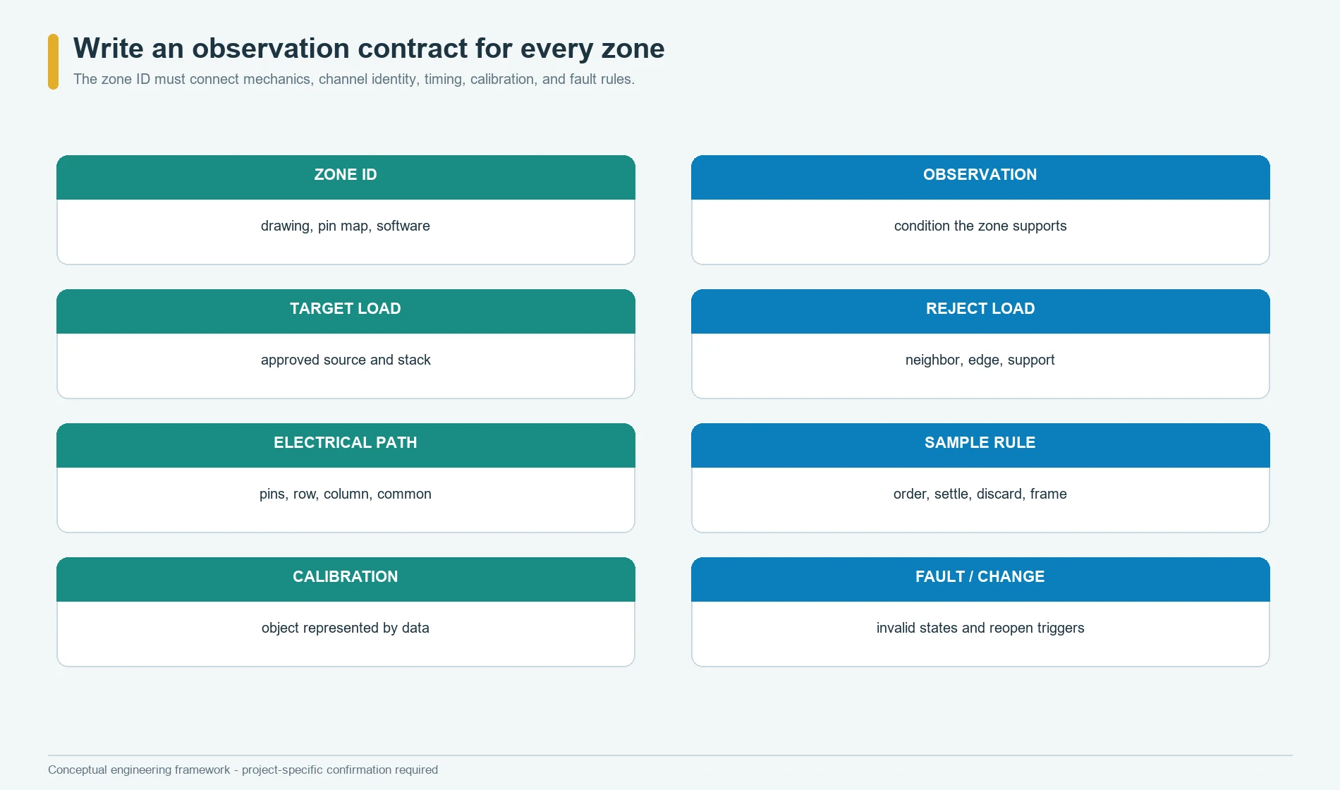
The zone contract is the central release record for a flexible pressure sensor array:
Zone ID | Required Observation | Target Load Path | Reject Load | Physical Feature | Electrical Path | Sample Rule | Calibration Object | Fault Rule | Change Trigger
Each field closes a different ambiguity.
Zone IDmust match the drawing, pin map, test software, calibration file, and system requirement.Required Observationstates the decision supported by the zone.Target Load Pathidentifies where load enters and what intermediate layers transfer it.Reject Loadnames neighboring, edge, support, handling, or assembly loads that must not create a valid observation.Physical Featureidentifies the actual pad, intersection, contact opening, or sensing area.Electrical Pathidentifies pins, row, column, common return, multiplexer channel, or ADC route.Sample Rulerecords order, dwell, discard, averaging, and frame timing where relevant.Calibration Objectstates whether coefficients belong to the loose array, a subassembly, or the complete installed stack.Fault Ruledescribes open, short, stuck, out-of-range, implausible, or cross-zone behavior.Change Triggerstates which material, geometry, circuit, fixture, software, or assembly changes require review.
This record also exposes false precision. If the target load path is unknown, a small printed zone cannot be assigned a credible effective footprint. If the scan rule is unknown, simultaneous pattern logic has no defined time basis.
Let the Load Footprint Set Zone Geometry
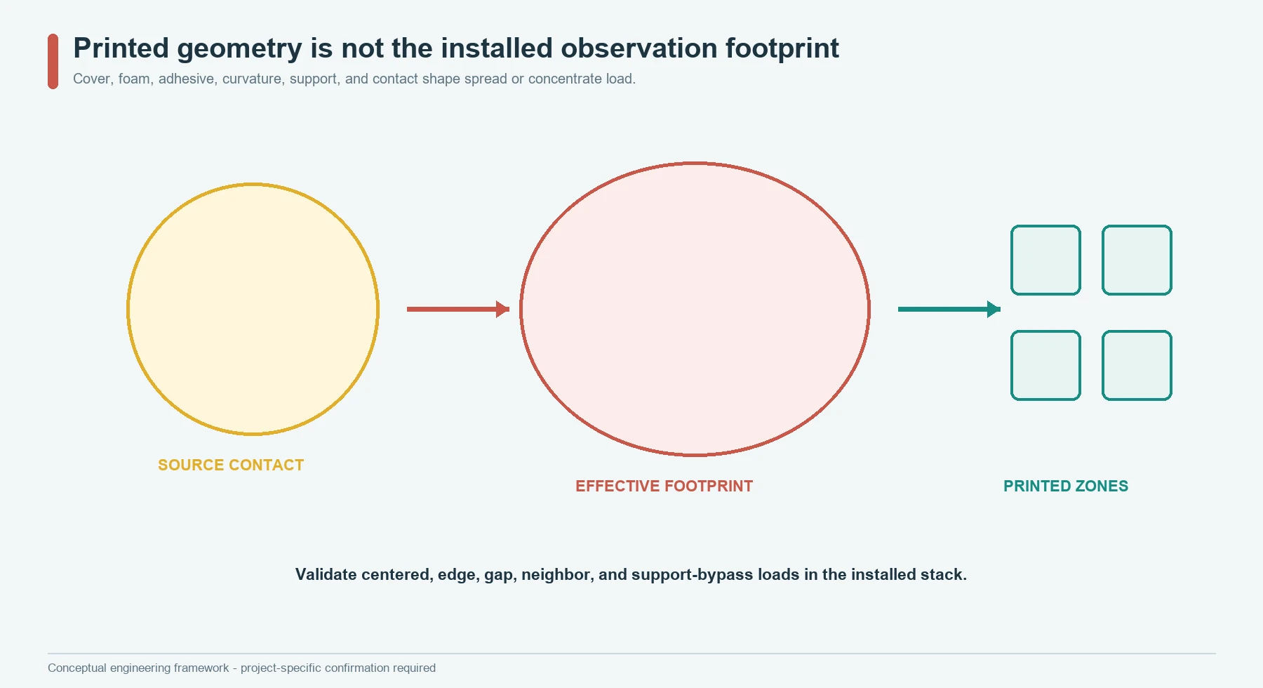
The electrical outline is not the same as the observed footprint. Covers, foam, elastomers, mounting films, load spreaders, upholstery, supports, and local curvature can spread or concentrate load before it reaches the sensing feature.
Interlink’s FSR integration guide and Tekscan’s mechanical integration material both treat contact geometry, support, actuator alignment, shear, and bending as part of force-sensor behavior.[3][6] The exact construction of a JASPER array may differ, but the integration boundary is the same: spatial response belongs to the complete contact stack.
Map at least five areas for each required load case:
- the source contact area;
- the footprint after the cover or cushion layer;
- the intended sensing feature;
- neighboring sensing features that may receive transferred load; and
- structural paths that can bypass the array.
Then test the expected extremes of position, contact shape, material condition, assembly tolerance, and support.
The right zone spacing is therefore not a generic gap copied from another sensor. It is the spacing that lets the installed assembly separate required states with enough margin. Two printed pads can be far apart electrically but coupled by a broad foam footprint. They can also be close on the drawing yet remain distinguishable when load is tightly guided.
Distinguish Geometric Resolution From Measurement Resolution
Adding smaller zones increases geometric density. It does not guarantee better spatial information.
The complete spatial resolution is limited by:
- width and variation of the applied contact;
- load spreading through intermediate layers;
- active-feature size and edge behavior;
- registration between sensing layers;
- placement tolerance in the product;
- electrical channel separation;
- scan timing and settling;
- signal-to-noise and repeatability;
- calibration coverage; and
- the decision logic applied to neighboring channels.
A development pressure-mapping instrument can help reveal where load travels through a seat, cushion, or interface. That instrument does not automatically define the embedded production array. The production design may intentionally use fewer, larger zones if the controller only needs a stable position or coverage decision.
Conversely, a dense array is not useful when the mechanical footprint is wider than several sensing elements and the algorithm cannot separate whether the spread came from the source, the cover, or electrical coupling.
Release geometric pitch, effective footprint, and system spatial resolution as three different objects. Only the last one describes what the installed system can distinguish.
Route Traces Without Hiding Channel Ownership
Zone layout and trace layout compete for the same flexible area. More sensing regions create more conductor paths, crossings or layer changes, convergence near the tail, and opportunities for local stiffness.
The routing review should show:
- unique conductor identity from zone to connector;
- shared rows, columns, or returns;
- trace corridors and prohibited sensing areas;
- crossings, jumpers, vias, or layer transitions if the construction uses them;
- conductor convergence into the tail;
- local neck-down or crowding;
- edge and cutout relationships;
- bend and strain regions;
- shielding or guard features if actually required;
- connector pin numbering and orientation; and
- continuity and isolation test points.
For a shared-return array, the return is a measured part of several channels. Its resistance, damage, contamination, and connector contact can move channels together. For a row-column array, every row and column participates in multiple element addresses. One open conductor can remove a line of observations; one unintended path can affect several intersections.
The route drawing should therefore communicate fault consequences, not just conductor artwork. A visually tidy fan-out can still make fault isolation impossible if channel identity changes between the array drawing, connector drawing, harness, and software table.
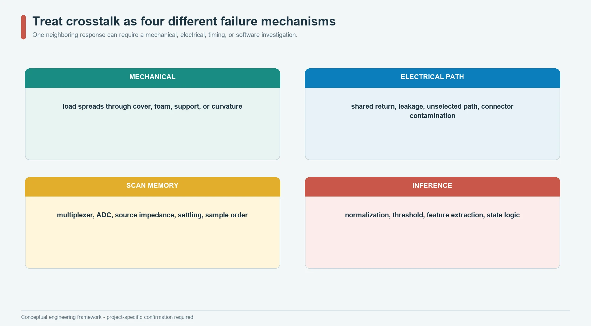
Treat Crosstalk as Four Separate Failures
Crosstalk is too broad to be a useful root cause. Separate it into four mechanisms:
| Crosstalk class | What moves between observations | Typical first checks | Primary owner |
|---|---|---|---|
| Mechanical | Physical load or deformation spreads into a neighboring effective footprint | cover, foam, actuator, support, curvature, preload, zone spacing | mechanical and sensor-stack design |
| Electrical path | Current, leakage, shared impedance, unselected paths, or insulation defects affect another channel | topology, common return, contamination, isolation, connector, damaged traces | sensor circuit and hardware |
| Scan-memory | A previous channel or switching event affects the next ADC result | source impedance, multiplexer behavior, acquisition time, scan order, settling, discarded samples | analog and firmware design |
| Inference | Filtering, normalization, feature extraction, or state logic converts one valid change into another zone’s decision | software map, filter state, normalization denominator, thresholds, temporal logic | algorithm and system design |
Texas Instruments describes ADC memory crosstalk as one input channel influencing the next channel after a multiplexer transition and identifies input settling and acquisition behavior as part of the problem.[7] Its multiplexer guidance also treats channel leakage, on-resistance, charge injection, bandwidth, crosstalk, off-isolation, and settling as selection parameters.[8]
Those references do not prove that a particular JASPER array has such errors. They define why the complete acquisition chain must be reviewed before a neighboring response is blamed on the printed sensor.
Prove Mechanical Crosstalk With Guard Loads
Mechanical crosstalk is measured with loads that deliberately challenge the border between required and rejected observations.
Use a fixture and product stack that can apply:
- a centered load on each zone;
- a load near every zone edge;
- a load in the gap between adjacent zones;
- a load over a trace corridor;
- a load near a cutout, rib, seam, or support transition;
- a load near the body-to-tail transition;
- two simultaneous loads on selected zone pairs;
- a prohibited-area load; and
- an off-axis or shifted contact representative of the application.
Record every channel, not only the target zone. A pass condition may be based on absolute neighbor response, a ratio, a classification margin, or a state outcome. The correct metric depends on whether the array is contact-type, analog, or calibrated for pressure.
Repeat selected conditions after the assembly has been installed, conditioned, flexed, or otherwise exposed to the states that matter. A flat loose array may show clean separation while the finished cushion spreads load across several zones.
The guard-load drawing should be part of the validation package. Otherwise a result such as neighbor low cannot be reproduced because the contact location, shape, support, dwell, and sequence are unknown.
Prove Electrical and Scan Crosstalk With Channel Permutations
Electrical and scan-memory effects can be separated from mechanics by changing the acquisition conditions while keeping the physical load stable.
Useful experiments include:
- reverse the scan order;
- alternate between a low-output and high-output channel;
- insert an unloaded or reference channel between selected channels;
- increase or decrease the allowed settling interval;
- compare the first sample after switching with later samples;
- hold the same load while changing only the multiplexer path;
- connect a controlled electrical substitute in place of the sensor;
- compare dedicated-channel and shared-path prototypes;
- test single open, short, leakage, and common-return faults; and
- permute channel labels in software to confirm the physical map remains correct.
If the apparent neighbor response follows scan order rather than physical position, the likely owner moves toward acquisition electronics or firmware. If it follows physical position while scan order changes, mechanical or printed-path coupling deserves attention.
Do not solve every cross-channel symptom by adding a longer moving average. Filtering can hide settling errors, delay real transitions, and mix samples from different physical moments. Preserve raw channel data and scan metadata until the mechanism is understood.
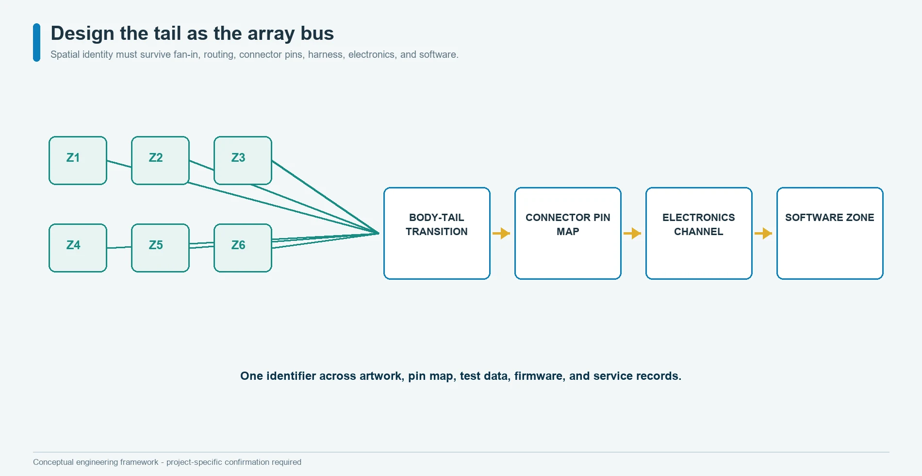
Design the Tail as the Array Bus
The tail carries the complete spatial identity of the array through a narrow, flexible region. It is not a generic cable attached after the sensing body is complete.
The tail design should control:
- conductor order from body to connector;
- row, column, zone, common, guard, and reference ownership;
- fan-in geometry and local stiffness;
- one-time forming versus repeated flexing;
- bend direction and unsupported length;
- transition between laminated regions;
- strain relief and connector pull;
- proximity to seat frames, clips, moving hardware, and sharp edges;
- insertion and service sequence;
- pin-one orientation and mating connector;
- electrical inspection and traceability.
Interlink warns against sharp bending, kinking, or damaging an FSR tail and emphasizes mechanical protection.[6] A multi-zone tail is more sensitive to documentation errors because one physical route carries several observation paths.
The pin map should be generated from the controlled electrical artwork, then checked against the connector drawing and acquisition configuration. Hand-entered duplicate maps invite channel swaps that can look like a sensor or algorithm failure.
Lamination and Registration Preserve Spatial Meaning
An array can pass continuity inspection and still lose its intended spatial behavior if internal layers shift.
Registration affects:
- overlap between opposing electrodes or contacts;
- spacer openings and contact gaps;
- force-sensitive material relative to conductors;
- adhesive keepouts around active areas;
- vent or pressure-equalization paths where used;
- edge sealing;
- trace-to-cut clearance;
- body-to-tail alignment; and
- final sensor placement relative to the product datum.
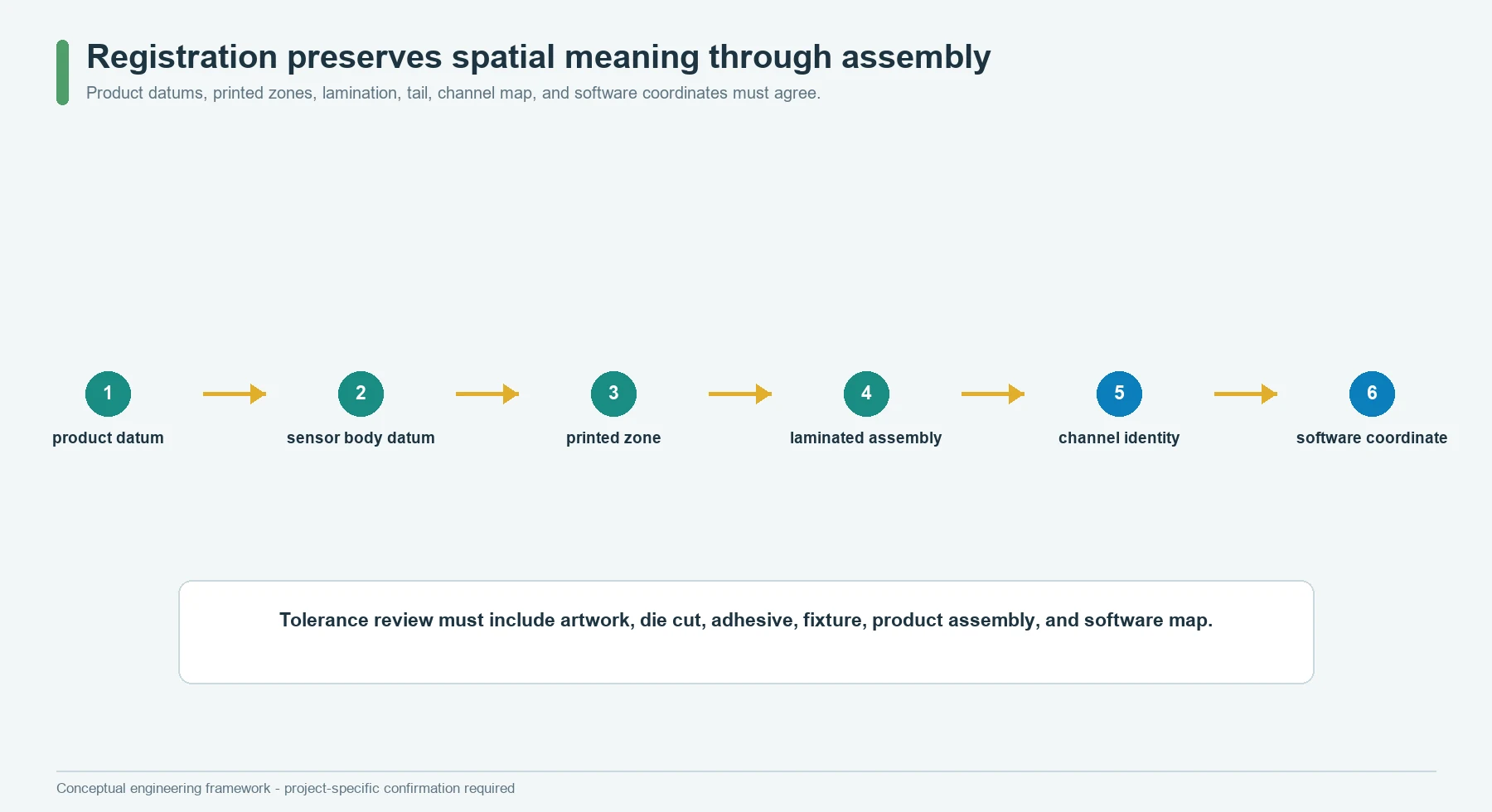
The release drawing should connect the coordinate chain:
product datum
    -> installed array datum
    -> cut outline
    -> internal layer registration
    -> sensing feature
    -> electrical channel
    -> software zone ID
A layer may be dimensionally acceptable by itself while the combined stack shifts the effective feature beyond the approved load path. Review the worst combined condition, not only each individual tolerance.
Bonding also changes mechanics. Adhesive can stiffen an area, constrain movement, bridge a designed gap, migrate into an opening, or create a local edge. Do not prescribe a universal lamination condition or material without the confirmed stack and process. The validation object must use the production-intent bonded structure.
Make the Scan Schedule Part of the Drawing
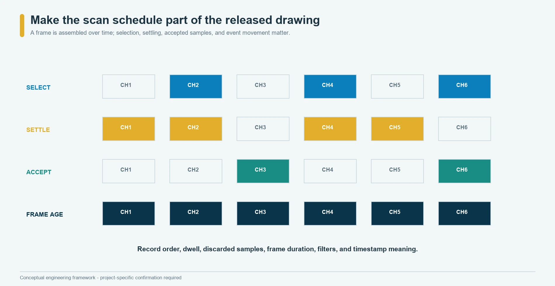
A scanned array has a time dimension. The controller does not receive the array value; it receives a sequence of channel observations that are assembled into a frame.
Record:
- row and column selection order;
- channel enable and disable states;
- acquisition interval after switching;
- first-sample discard rule if used;
- samples averaged per channel;
- frame rate and maximum frame age;
- timestamp location;
- filter state;
- missing-channel behavior;
- range or gain changes;
- synchronization with external events; and
- diagnostic insertions or reference measurements.
TI’s ADC guidance shows why the acquisition chain must settle after a channel transition and why the previous channel can affect the next conversion.[7] The correct timing depends on the multiplexer, ADC, source impedance, drive circuit, signal range, required accuracy, and board implementation. This article does not publish a universal delay.
Sequential scanning also matters when the physical event changes during the frame. If the first zone is sampled before a load shift and the last zone after it, the combined frame may represent no single instant. The system requirement should define how much frame skew is acceptable and whether the application instead needs simultaneous channels or a simpler state architecture.
Calibrate the Array in Three Layers
One calibration label should not cover three different jobs.
Layer 1: sensor equalization and channel health
The first layer compensates or characterizes differences among sensing elements and channels so that a common physical condition does not appear different only because of element sensitivity or electrical gain. Tekscan calls the process used to reduce variation among sensing elements equilibration.[4]
This layer may include baseline, element sensitivity, channel gain, offset, and rejection of unstable or damaged elements. It does not by itself convert the output into pressure.
Layer 2: physical signal calibration
Tekscan defines calibration as converting sensor output into an engineering unit using known applied loads.[5] For an array intended to report pressure or force-related values, the calibration must identify the loading fixture, contact shape, support, conditioning, electronics, range, dwell, sequence, and interpolation method.
A contact-type array that only reports open or closed states may not need an engineering-unit calibration. It still needs actuation, release, neighbor, and fault validation.
Layer 3: system decision calibration
The final layer converts channels or calibrated values into the required state. It may use zone thresholds, relative patterns, timing, plausibility, and fault rules.
NIST’s measurement-process guidance separates measurement design, repeatability, reproducibility, calibration, gauge studies, and uncertainty.[9][10][11] Use that separation when deciding whether a failed state came from the physical sensor, acquisition chain, calibration model, assembly, or classification rule.
The calibration record must name the object that remains valid after production changes. Coefficients from a loose flat array do not automatically approve the same array under foam, adhesive, curvature, or preload.

Interpret Patterns Without Inventing Pressure
The software should report only what the sensing and calibration chain supports.
raw channel samples
        |
electrical health and fault checks
        |
approved baseline or equalization
        |
zone values or contact states
        |
spatial and temporal features
        |
valid, invalid, unknown, or fault decision
Possible spatial features include:
- active zone set;
- number of active zones;
- left-right or front-rear balance;
- maximum channel and its location;
- weighted location after approved normalization;
- coverage of required regions;
- prohibited-region activation;
- neighbor consistency; and
- change from an approved baseline pattern.
Possible temporal features include dwell, transition order, persistence, recovery, and rate of pattern change. These features can support a system decision, but they do not create pressure units.
Keep an unknown or fault outcome when the pattern falls outside the calibrated and validated domain. Forcing every sample into a normal application state can hide opens, shorts, shifted assembly, unapproved contacts, overload, or simultaneous conditions that were never tested.
For automotive equipment, JASPER supplies an interface component, not the complete vehicle classification or safety decision. The OEM or system integrator owns electronics, software, diagnostics, safety analysis, compliance, and vehicle-level validation.
Prototype the Unknowns in the Right Order
A prototype should isolate the uncertain relationship before several uncertainties are combined.
Use a sequence such as:
- Observation mockup: mark intended zones on the real product and confirm that each zone supports a named decision.
- Load-footprint study: measure or map how representative contacts transfer through the cover, cushion, or support.
- Topology coupon: compare dedicated, shared-return, or matrix addressing for signal separation and fault behavior.
- Routing and tail sample: confirm fan-in, connector, bends, installation, and strain relief.
- Laminated array: evaluate registration, zone response, isolation, and body-to-tail transition.
- Acquisition prototype: freeze channel map, scan order, settling method, raw-data format, and diagnostics.
- Installed assembly: calibrate or validate the production-intent mechanical stack.
- System-state build: approve required patterns, rejected loads, timing, unknown states, and faults.
JASPER’s prototyping capability can provide a route for drawing and sample review after the sensing principle and validation inputs are confirmed. The capability page does not prove a particular array technology, pressure range, calibration service, or passed application test.
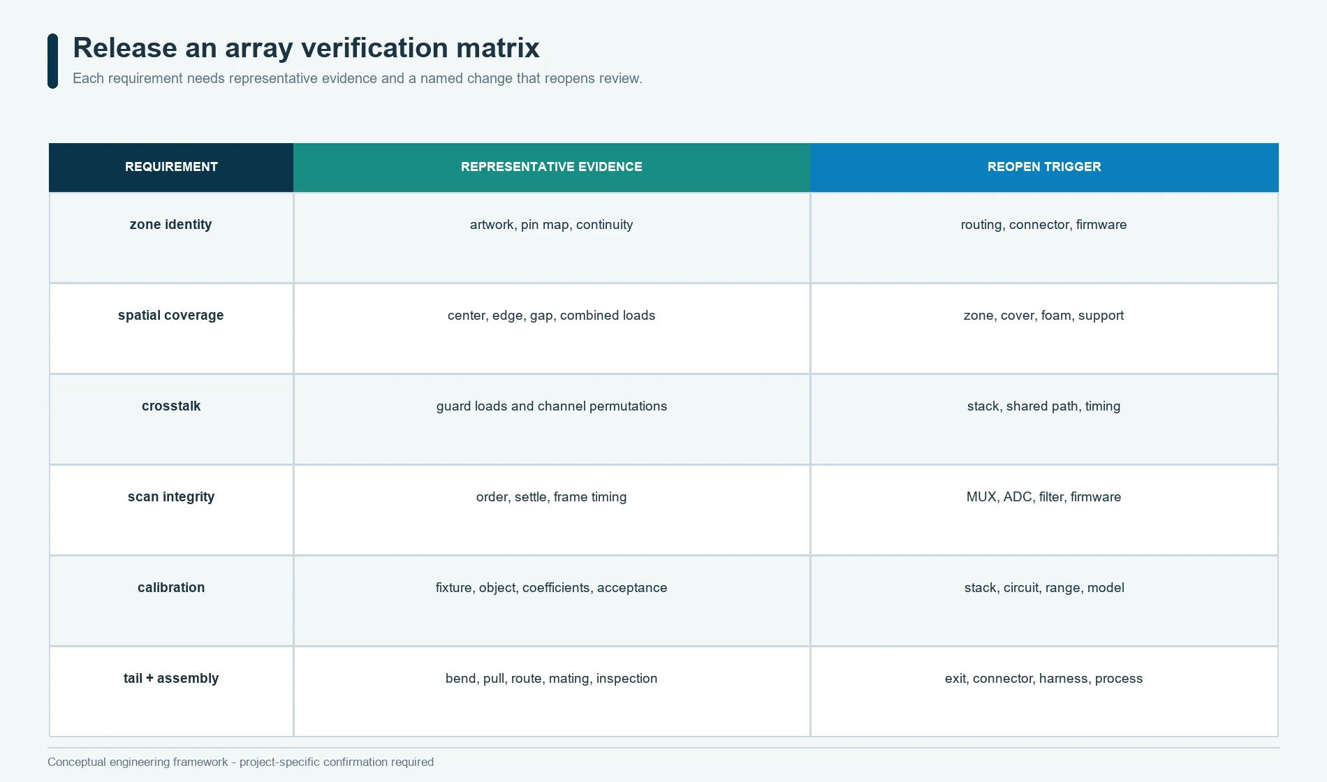
Release an Array Verification Matrix
The final design should be released with evidence that follows the zone contract.
| Requirement group | Representative evidence | Change that reopens review |
|---|---|---|
| Zone identity | artwork, pin map, channel map, software map, continuity record | routing, connector, pin order, firmware map |
| Spatial coverage | centered, edge, gap, prohibited-area, and combined-load tests | zone geometry, product datum, foam, cover, support, mounting |
| Mechanical isolation | neighbor response under guard loads and assembly extremes | layer stiffness, adhesive, preload, curvature, contact shape |
| Electrical isolation | leakage, open, short, common-path, and unselected-state tests | conductor, insulation, connector, contamination control |
| Scan integrity | order permutation, settling study, frame timing, reference-channel check | multiplexer, ADC, source circuit, timing, filter, firmware |
| Calibration | approved fixture, load cases, object identity, coefficients, uncertainty or acceptance record | stack, electronics, range, fixture, algorithm |
| Decision logic | valid, rejected, unknown, and fault pattern set | thresholds, normalization, feature extraction, state logic |
| Tail and assembly | bend, pull, route, insertion, mating, and installed inspection | exit location, tail stack, connector, harness, assembly process |
Use the quality and testing framework to connect each requirement to a specimen, method, result, acceptance rule, and retained record. A generic statement such as array tested does not identify which topology, load path, channel map, scan schedule, calibration, or state logic was approved.
Know When an Array Is the Wrong Architecture
Do not use a flexible pressure sensor array when:
- one contact state already answers the system question;
- the product needs total force or weight through a controlled structural load path rather than a distributed pattern;
- the required spatial detail is finer than the mechanical stack can preserve;
- the event requires genuinely simultaneous acquisition that the proposed scanned architecture cannot provide;
- the available tail, connector, electronics, or service plan cannot support the channel count;
- the environment or assembly cannot protect the flexible stack and tail;
- the project expects pressure accuracy without a defined calibration object;
- the required safety, medical, automotive, or regulatory evidence is outside the supplier and system scope; or
- the algorithm has no valid unknown or fault state.
The better result may be a single-zone contact mat, an FSR, a structural force transducer, a commercial pressure-mapping system used only for development, or another sensing principle. More zones are justified only when they produce information the system can verify and use.
Frequently Asked Questions
What is a flexible pressure sensor array?
It is a thin assembly with multiple pressure-responsive regions and an electrical architecture that lets the connected system distinguish those observations. The sensing sheet, tail, electronics, timing, calibration, and interpretation form one array system.
How many zones should an array use?
Use the fewest zones that support the required spatial decision, coverage, diagnostics, and fault handling. More zones add routing, connector, acquisition, calibration, software, and validation work.
Is a row-column matrix always better than dedicated channels?
No. A matrix can reduce conductor count, but it adds shared paths, scan timing, settling, unselected-state, and fault-isolation work. Dedicated channels can be easier to diagnose but consume more routing.
Why can a neighboring zone respond to one load?
The cause may be mechanical load spreading, electrical shared paths, ADC or multiplexer memory, or software inference. Each mechanism needs a different diagnostic test.
Does a dense array guarantee higher spatial resolution?
No. Installed resolution is limited by contact size, load spreading, registration, signal separation, scan behavior, calibration, and the decision logic, not only the printed pitch.
Does JASPER provide a calibrated pressure-mapping instrument?
This article does not claim that scope. JASPER can review a custom flexible sensor construction, while the sensing principle, electronics, calibration, software, and validation boundary require confirmation.
What should an OEM send for a multi-zone review?
Send the required decision, zone contract, load cases, product stack, array envelope, topology preference, channel map, tail and connector, acquisition assumptions, calibration boundary, fault rules, test plan, and quantities.
Sources
- JASPER Electronics,
Flexible Membrane Seat Pressure Sensor, current commercial product scope: https://www.jasperele.com/products/car-seat-occupancy-sensor/flexible-membrane-seat-pressure-sensor/ - Tekscan,
Pressure Mapping Technology, official manufacturer system overview: https://www.tekscan.com/products-solutions/pressure-mapping-technology - Tekscan,
FlexiForce Mechanical Integration Guides, official force-sensor integration guidance: https://www.tekscan.com/resources/datasheets-guides/flexiforce-integration-guides - Tekscan,
What Is Equilibration?, official pressure-mapping support guidance: https://www.tekscan.com/support/faqs/what-equilibration - Tekscan,
What Is Calibration?, official pressure-mapping support guidance: https://www.tekscan.com/support/faqs/what-calibration - Interlink Electronics,
FSR 400 Series Integration Guide, official manufacturer PDF: https://www.interlinkelectronics.com/downloads/integration-guides/fsr-400-series-integration-guide.pdf - Texas Instruments,
Methods for Mitigating ADC Memory Cross-Talk, official application report: https://www.ti.com/lit/pdf/spracw9 - Texas Instruments,
Discrete ADC Input Expansion Using Precision Multiplexers, official application report: https://www.ti.com/lit/pdf/scda031 - National Institute of Standards and Technology,
Measurement Process Characterization - Introduction: https://www.itl.nist.gov/div898/handbook/mpc/section1/mpc1.htm - National Institute of Standards and Technology,
Measurement Process Characterization - Measurement in Process Qualification: https://www.itl.nist.gov/div898/handbook/mpc/section2/mpc2.htm - National Institute of Standards and Technology,
Measurement Process Characterization - Uncertainty in Measurement: https://www.itl.nist.gov/div898/handbook/mpc/section3/mpc3.htm
Review a Multi-Zone Sensor Layout
Submit the following through the JASPER request-for-quote form:
- application and final system decision;
- product drawing and installation datum;
- source contacts, load directions, and expected position changes;
- cover, foam, support, adhesive, curvature, and preload stack;
- required zones and the purpose of each zone;
- required rejected or prohibited load cases;
- contact, analog, matrix, or other output preference if known;
- channel count, connector, tail route, bend, and harness constraints;
- acquisition electronics and scan assumptions;
- required engineering units, thresholds, patterns, timing, and fault states;
- prototype quantity and production forecast;
- environmental, lifecycle, service, and change-control requirements; and
- validation fixtures, acceptance criteria, records, and approval owner.
JASPER can review a custom flexible membrane layout after those inputs are available. The first deliverable should be the zone observation contract and topology decision, not a finished-looking grid with undefined spatial meaning.
Ready to Start Your Project?
Tell us about your membrane switch, keypad, or graphic overlay requirements. Our engineering team will review your specifications and provide a detailed quote.