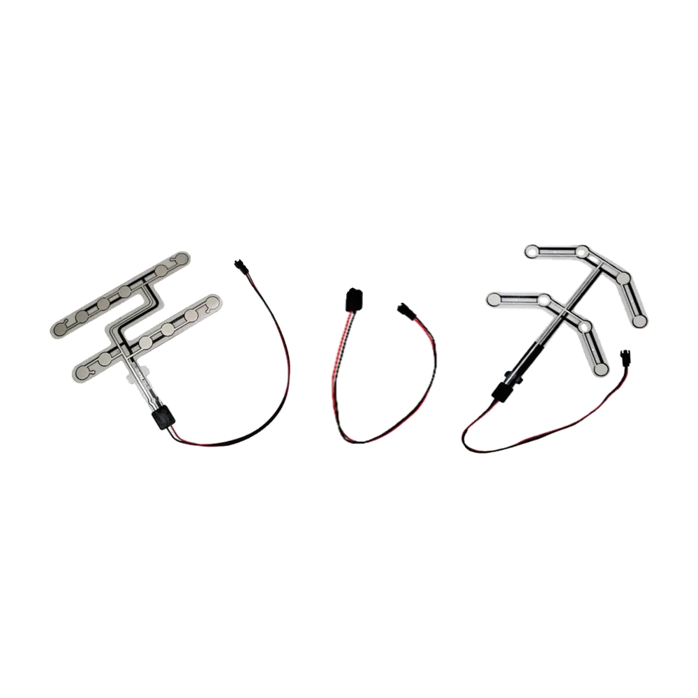
A seat pressure sensor describes how a component responds to load at the seat, while a seat occupancy sensor describes what the complete system must decide: whether the seat is empty, occupied, transitional, or in a fault state. One pressure-sensitive component can provide the input for an occupancy system, but the terms are not automatically interchangeable. A contact mat may provide only an open/closed state. An FSR may provide a changing resistance. The controller, seat mechanics, thresholds, timing, and diagnostics determine the final occupancy result.
For an OEM program, the practical starting point is the required output, not the product name. A custom car seat pressure sensor can be reviewed against the cushion stack, sensing zone, trigger condition, circuit, tail route, connector, and validation plan. If the specification only says “occupancy sensor,” those same inputs are still needed before the sensing architecture can be selected.
Updated: July 15, 2026
- Quick Comparison: Seat Pressure Sensor vs Seat Occupancy Sensor
- One Term Describes the Method; the Other Describes the Function
- What Outputs Can a Seat Pressure Sensor Provide?
- Contact or switch output
- Analog resistive output
- Multi-zone output
- Conditioned or digital output
- What Does a Seat Occupancy Sensor Need to Output?
- Force, Pressure, Mass, Weight, and Occupancy Are Different Quantities
- Which Sensor Architecture Fits the Engineering Objective?
- Objective 1: Detect a stable occupied/empty condition
- Objective 2: Set an adjustable load-related threshold
- Objective 3: Detect load position or pattern
- Objective 4: Estimate absolute or structural load
- Objective 5: Classify complex occupant or object conditions
- How Does Mechanical Integration Change the Result?
- How Do Electronics and Calibration Differ?
- Contact-type sensor
- Analog sensor
- What Do Accuracy and Resolution Mean for Each Sensor?
- Application Decision Matrix
- Common Specification Mistakes
- Buying by search term
- Asking for a universal trigger weight
- Treating a contact mat as a low-resolution analog sensor
- Treating an FSR as a load cell
- Calibrating only the bare sensor
- Ignoring release and dwell
- Leaving fault ownership undefined
- Assuming the component owns vehicle compliance
- OEM Input Checklist
- Choose the Sensor Architecture Before Requesting a Quote
- Sources
Quick Comparison: Seat Pressure Sensor vs Seat Occupancy Sensor
| Engineering question | Seat pressure sensor | Seat occupancy sensor | Why the distinction matters |
|---|---|---|---|
| What does the term describe? | The sensing element or method that responds to force, compression, or load transfer | The system function that decides whether a seat meets an occupancy rule | Method and function can belong to different parts of the signal chain |
| What is the primary objective? | Produce a repeatable raw contact or load-related signal | Produce a valid empty, occupied, transitional, or fault state | A usable raw signal is not yet a system decision |
| What outputs are possible? | Open/closed contact, resistance change, voltage after conditioning, or multiple zone signals | Logic state, classified state, warning input, digital message, or diagnostic state | The occupancy output depends on electronics and software as well as the sensor |
| Does it measure pressure in pascals? | Not necessarily; the commercial term may refer to a pressure-sensitive pad rather than a calibrated pressure instrument | Usually no; occupancy is a categorical system result | The measured quantity and units must be stated explicitly |
| Does it need a controller? | A contact can be read directly, but most applications still need qualification and diagnostics | Yes, unless the complete logic is built into a conditioned module | Thresholds, debounce, fault checks, and system actions need ownership |
| Can it report exact occupant weight? | Not automatically | Not automatically | Absolute load measurement requires a suitable mechanical architecture and calibration |
| Where is it installed? | Commonly in or under the cushion, foam, trim, or another controlled load path | May include the pressure element plus electronics elsewhere in the seat or vehicle | Installation changes the force reaching the sensor |
| Best fit | Projects that define a raw contact, relative-load, or zone response | Projects that define a required seat-state decision | Choose by the required decision and validation evidence |
The same physical assembly may be called both names in a quotation. That is acceptable only when the drawing and interface specification make the sensing principle, raw output, and system responsibility clear.
One Term Describes the Method; the Other Describes the Function
The simplest way to separate the terms is to place them in the complete signal path:
Occupant or object load
          |
          v
Seat trim, foam, and support distribute the load
          |
          v
Pressure-sensitive element or load sensor
          |
          v
Contact, resistance, voltage, zone pattern, or digital output
          |
          v
Signal conditioning, thresholds, timing, and fault checks
          |
          v
Empty / occupied / transitional / fault decision
          |
          v
Reminder, comfort, control, monitoring, or other system action
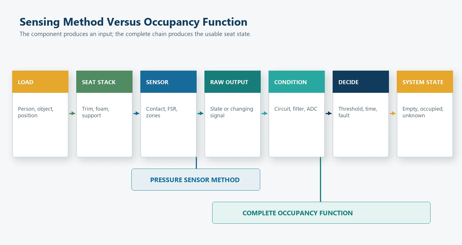
Seat pressure sensor normally points to the sensing-element portion of this chain. Seat occupancy sensor may refer to the sensor component, but technically it points to the decision function. The occupancy function can be built from a pressure mat, FSR, structural load sensor, capacitive sensor, multiple inputs, or a conditioned module.
This distinction prevents two common specification errors. First, a buyer should not request analog pressure data when the application only needs a stable occupied/empty switch. Second, a buyer should not expect a simple contact mat to provide calibrated load or occupant-classification data that the architecture was not designed to measure.
What Outputs Can a Seat Pressure Sensor Provide?
The words pressure sensor do not identify one electrical interface. Confirm the output before comparing suppliers or samples.
Contact or switch output
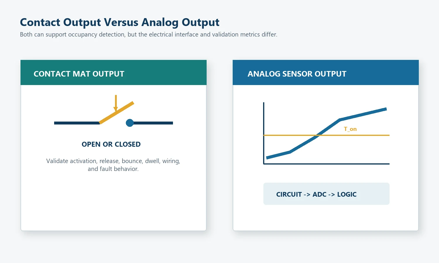
A contact-type pressure mat contains conductive regions separated by a controlled gap or spacer structure. Applied load closes the contact; load removal allows it to reopen. The useful output is a state:
Open contact   -> inactive candidate
Closed contact -> active candidate
The word candidate is important. The controller may still need debounce, open/short diagnostics, startup handling, and release logic before it declares the seat occupied.
A contact mat is often the cleanest architecture when the only required information is whether a validated load condition is present. It does not need to simulate an analog measurement to be useful.
Analog resistive output
A force sensing resistor normally decreases in resistance as applied force increases. The electronics may read the sensor through a voltage divider, conductance circuit, amplifier, or other interface.
An analog signal allows an adjustable threshold, relative load trend, or comparison between zones. It also adds dependence on the loading area, support, circuit, sampling, calibration, drift, and acceptable error. FSRs can support force sensing, but they are not load cells or strain gauges. That boundary is directly relevant to seat projects.
Multi-zone output
A flexible sensor can contain several contact or analog zones. The controller may evaluate:
- any approved zone active;
- a required combination of zones;
- individual zone thresholds;
- a sum or comparison of analog zones;
- a stable spatial pattern; or
- zone disagreement as a transitional or fault condition.
More zones provide more position information, but they also require more traces, connector pins, input channels, calibration data, and state combinations.
Conditioned or digital output
A module may contain the sensing element, analog front end, conversion, diagnostics, and digital communication. In that case, the module supplier and system owner must define which functions are inside the module and which remain in the vehicle or equipment controller.
The word digital does not prove that the underlying measurement is more accurate. It only describes how the conditioned result is communicated.
What Does a Seat Occupancy Sensor Need to Output?
An occupancy system usually needs a decision that other functions can use. A useful state model is:
| State | Meaning | Typical system treatment |
|---|---|---|
| Empty | Valid input is inside the approved empty condition | No occupied-seat action |
| Occupied | Valid input or zone pattern meets the approved occupied condition | Enable the intended reminder, comfort, or control logic |
| Transitional | Input is changing, unstable, or between decision boundaries | Hold the previous state or wait for qualification |
| Fault | Electrical or logical plausibility check failed | Follow the project diagnostic and safety strategy |
| Unknown | Startup or insufficient data prevents a valid decision | Delay the decision until validation conditions are met |
For a basic seat belt reminder input, the system may only need stable empty and occupied states plus fault detection. For a comfort feature, relative load or zone position may add value. For occupant classification or absolute load measurement, a thin pressure pad may be insufficient and another architecture may be required.
JASPER’s seat occupancy sensor options cover several seat-focused product routes. The final output and system function must still be confirmed from the OEM specification.
Force, Pressure, Mass, Weight, and Occupancy Are Different Quantities
These terms are often mixed in RFQs. They should be separated before a drawing or acceptance test is approved.
| Term | Engineering meaning | Typical unit or form | Seat-project caution |
|---|---|---|---|
| Force | A mechanical interaction that can change motion or deform a structure | newton, N | The sensor sees only the force transferred through its local load path |
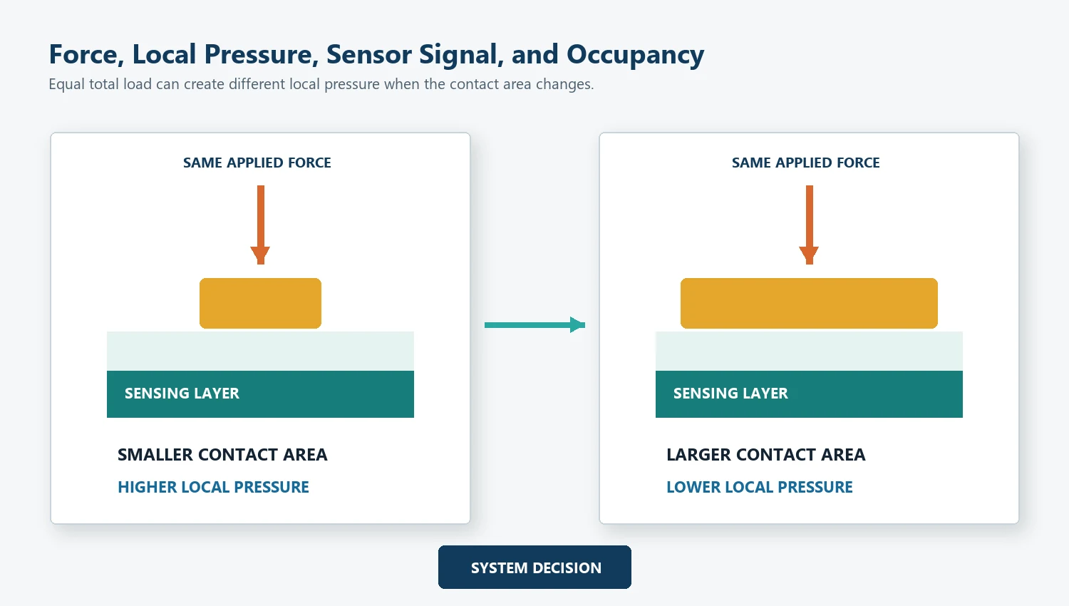
| Pressure | Force distributed over an area | pascal, Pa, equal to N/m2 | Local pressure changes when the contact area or foam distribution changes |
| Mass | Quantity of matter | kilogram, kg | A seat sensor does not directly measure mass unless the system model supports that inference |
| Weight | Force produced by gravity acting on mass | newton, N | Common language uses kilograms, but the physical quantity is force |
| Relative load signal | Sensor output that changes with load but may not be an absolute measurement | resistance, voltage, ADC count, conductance, or normalized value | Calibration is specific to mechanics, electronics, and conditions |
| Occupancy state | A decision that a seat meets an approved empty or occupied rule | state or digital code | It is a classification result, not a physical unit |
The SI defines force in newtons and pressure in pascals. In commercial seat-sensor language, however, seat pressure sensor may describe a pressure-responsive pad that produces a contact or resistance signal rather than a calibrated pressure value. The specification should state the actual output and acceptance method instead of relying on the product name.
Which Sensor Architecture Fits the Engineering Objective?
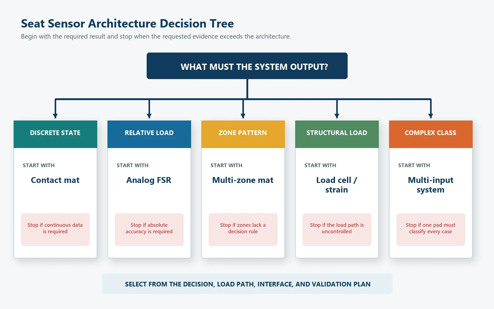
Start with the decision the system must make.
Objective 1: Detect a stable occupied/empty condition
A contact-type mat is a strong starting point when:
- only a discrete state is needed;
- the seat load path can close and release the contact repeatably;
- the installation can control preload;
- the controller can check open, closed, and fault conditions; and
- no continuous load data is required.
The main risk is mechanical variation. Foam, trim, sensor position, support, and assembly tolerance can move the activation and release conditions.
Objective 2: Set an adjustable load-related threshold
An FSR or another analog pressure-sensitive element is useful when:
- the controller needs a signal that changes with load;
- the threshold may need adjustment;
- relative load bands or trends are useful;
- several analog zones will be compared; or
- the project can calibrate the complete mechanical and electrical chain.
The main risks are nonlinearity, loading-area dependence, drift, hysteresis, circuit variation, and overclaiming measurement accuracy. Thin-film force sensors can detect and measure force in embedded applications, but sensor selection and calibration still depend on the actual integration.
Objective 3: Detect load position or pattern
A multi-zone contact or analog mat is appropriate when the system needs spatial information. Examples include checking whether load reaches an approved cushion region, comparing left and right zones, or identifying a stable pattern.
Do not add zones without a decision rule. Each zone should have a purpose, an electrical channel, a fault strategy, and a validation case.
Objective 4: Estimate absolute or structural load
If the project needs a traceable absolute load estimate, low uncertainty across a wide range, or load measurement independent of local cushion pressure, evaluate a structural load path, strain-based sensor, load cell, or another measurement architecture.
A printed pressure mat should not be selected solely because it is thin. The measurement objective may require a different component class.
Objective 5: Classify complex occupant or object conditions
Complex classification may require multiple sensors, structural load data, seat position, buckle status, zone patterns, or other inputs. A single pressure-sensitive pad cannot be assumed to distinguish every person, object, posture, and seat condition.
The automotive application determines the system boundary. The OEM or Tier 1 team owns final classification, diagnostics, warning behavior, restraint logic, and vehicle-level validation.
How Does Mechanical Integration Change the Result?
The sensing element does not receive the original occupant load directly. The seat redistributes it:
Occupant or test load
        |
        v
Upholstery and trim tension
        |
        v
Foam stiffness, contour, and compression
        |
        v
Protection, adhesive, and sensor position
        |
        v
Sensing zone
        |
        v
Seat pan, support, or cushion structure
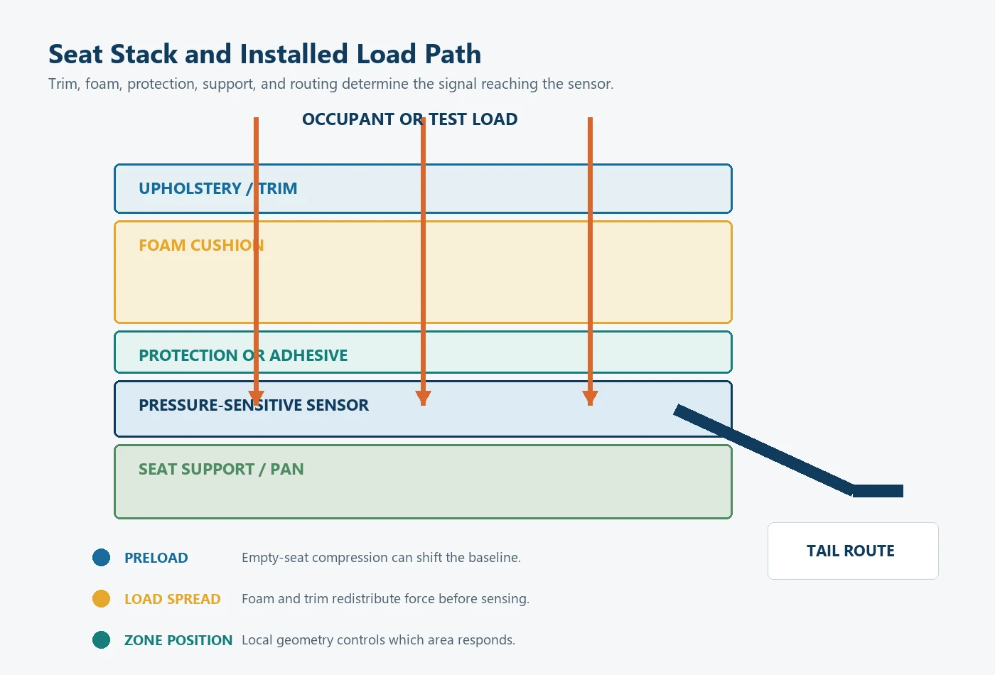
The same sensor can produce a different output when any part of this stack changes. Important variables include:
- cushion contour and foam condition;
- upholstery tension;
- sensor depth and orientation;
- sensing-zone size and position;
- local contact area;
- preload in the empty seat;
- adhesive or protective-layer stiffness;
- support openings and ribs;
- tail routing and connector strain;
- temperature, humidity, dwell, and recovery;
- repeated installation; and
- seat-to-seat assembly variation.
For that reason, a bench test of the bare component is useful for incoming inspection or electrical comparison, but it does not prove the final seat decision. Prototype validation should use the representative seat stack and the real circuit.
How Do Electronics and Calibration Differ?
Contact-type sensor
The controller usually reads continuity or a logic level. The important values are not analog resolution but:
- activation condition;
- release condition;
- contact bounce;
- stable on and off time;
- open-circuit and short-circuit behavior;
- leakage or contamination effects;
- startup state; and
- response after dwell and repeated loading.
Analog sensor
The controller must define:
- excitation or measurement circuit;
- ADC range and reference;
- sample rate;
- filtering;
- signal direction;
- baseline;
- threshold or load bands;
- rising and falling decision points;
- fault limits; and
- recalibration or change-control rules.
For a signal that increases with load, a generic occupancy rule can be:
Empty -> Occupied when signal >= T_on
Occupied -> Empty when signal <= T_off

with T_off < T_on
Separate rising and falling thresholds create hysteresis and reduce repeated switching around one boundary. Comparator circuits use the same principle. Debounce is different: it requires the candidate state to remain valid for a defined time or sample count.
Neither hysteresis nor filtering can repair overlapping steady-state data. If required empty and occupied cases occupy the same signal range, the sensor position, mechanics, zones, circuit, or system architecture must change.
What Do Accuracy and Resolution Mean for Each Sensor?
Asking whether one sensor is “more accurate” is incomplete. Accuracy must refer to a defined result.
| Result being evaluated | Relevant metric | Misleading substitute |
|---|---|---|
| Contact mat state | Activation/release repeatability and correct-state rate across approved cases | ADC resolution |
| Analog FSR signal | Repeatability, hysteresis, drift, nonlinearity, calibration error, and signal-to-noise under stated conditions | One resistance value from one load |
| Multi-zone pattern | Zone coverage, zone-to-zone consistency, pattern confusion, and channel faults | Number of zones alone |
| Occupancy decision | False occupied, missed occupied, transition time, fault detection, and behavior across seat builds | Bare-sensor bench accuracy |
| Absolute load estimate | Calibration error, uncertainty, repeatability, bias, creep, environmental sensitivity, and load-path control | Calling the part a weight sensor |
NIST measurement-process guidance separates repeatability, reproducibility or longer-term variability, calibration, bias, gauge studies, and uncertainty. That structure is more useful than one undefined accuracy percentage.
Resolution also depends on the output. A contact mat has state resolution: open or closed, perhaps across several zones. An analog sensor has electrical resolution, but more ADC counts do not create more mechanical information if the seat and sensor response are unstable.
Application Decision Matrix
| Application requirement | Recommended starting point | Data needed before selection | Stop condition |
|---|---|---|---|
| Occupied/empty input for a seat belt reminder | Contact mat or validated analog threshold | Seat stack, required occupied cases, release cases, circuit, diagnostic strategy | Required occupied and empty cases cannot be separated |
| Enable a seat comfort feature | Contact or analog sensor depending on required control | Activation logic, allowable delay, load position, environment | Feature requires precise load data not available from the sensor |
| Detect where load is applied | Multi-zone contact or analog mat | Zone purpose, layout, channel count, pattern rules | Zones have no defined system decision |
| Monitor relative load change | Analog FSR or other load-related sensor | Load range, contact area, mechanics, circuit, calibration method | Buyer requires absolute accuracy without a suitable reference |
| Estimate structural load | Load cell, strain-based, or controlled structural architecture | Load path, mounting, range, uncertainty target, calibration | Thin cushion mat is mandated despite incompatible measurement needs |
| Complex occupant classification | Multi-input system | Required classes, confusion cases, diagnostics, regulatory and system requirements | One sensor is expected to classify every condition |
| OEM seat prototype comparison | Architecture matched to the final output | Representative seats, samples, circuit, fixture, test matrix | Only bare-component finger-press testing is available |
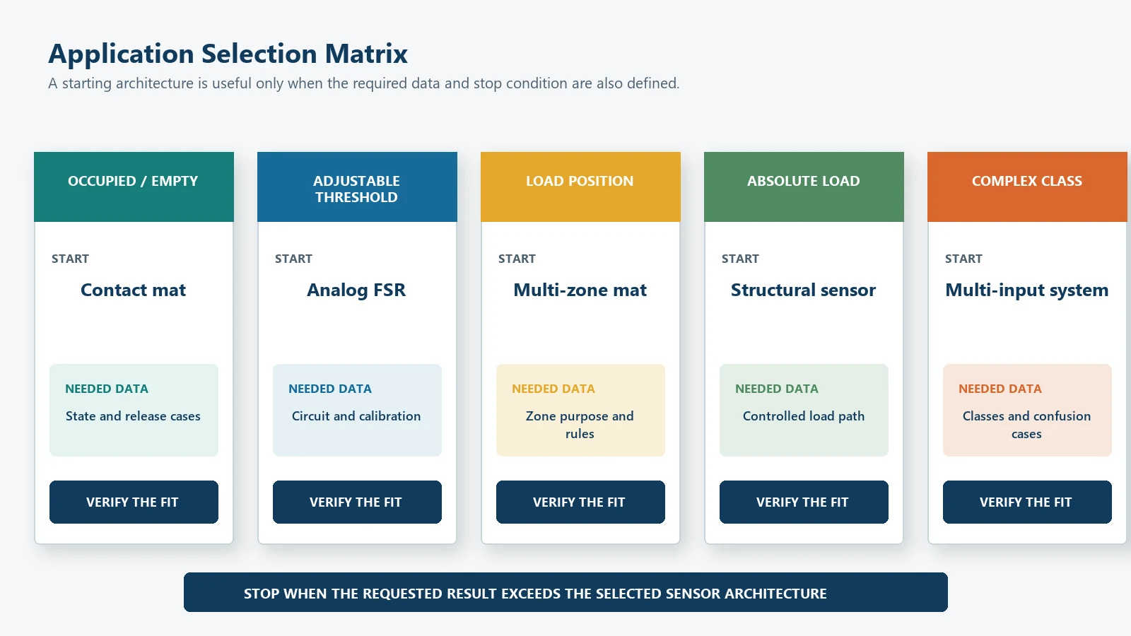
This matrix is a starting point, not a product certification. The approved architecture should follow recorded prototype data.
Common Specification Mistakes
Buying by search term
Two suppliers may use the same product name for different outputs. Ask for the circuit, state behavior, resistance behavior, zone count, and test method.
Asking for a universal trigger weight
The sensor responds to a local load path, not the occupant’s total mass in isolation. Contact area, posture, foam, support, and sensor position change the input.
Treating a contact mat as a low-resolution analog sensor
A contact closure is a valid discrete output. It should be specified and validated as a switch, not described with invented analog accuracy.
Treating an FSR as a load cell
An FSR can provide useful relative force information, but its mechanics and calibration differ from a strain-gauge load cell. Select the technology by the required measurement result.
Calibrating only the bare sensor
Bare-sensor testing does not include trim preload, foam distribution, support, seat assembly variation, or the production cable route.
Ignoring release and dwell
Activation is only half of the behavior. Record release, recovery after a sustained load, and state stability during movement.
Leaving fault ownership undefined
Open circuit, short circuit, disconnected connector, stuck state, out-of-range analog value, and zone disagreement need explicit treatment.
Assuming the component owns vehicle compliance
Vehicle-level occupant protection and reminder requirements belong to the complete system and program. A sensor component or component test does not by itself establish vehicle compliance.
OEM Input Checklist
Send the following information before freezing the sensor type:
- Application and seat position.
- Required final decision: contact, occupied/empty, relative load, load estimate, zones, or conditioned message.
- Empty, occupied, transitional, unknown, and fault definitions.
- Seat drawing, cushion section, trim, foam, support, and sensor location.
- Sensing-zone dimensions and coverage objective.
- Required load cases, contact areas, positions, dwell, and loading direction.
- Tail route, cable length, connector, pinout, and strain relief.
- Electrical interface, supply, pull-up or divider, ADC, thresholds, timing, and diagnostics.
- Environmental, lifecycle, cleaning, and mechanical-abuse conditions.
- Prototype samples, seat builds, repetitions, and acceptance rules.
- Drawing format, prototype quantity, annual quantity, and documentation needs.
- Functions owned by JASPER, the Tier 1 supplier, the OEM, and the final controller.
JASPER’s testing and quality-control capabilities can support confirmed component checks. The project owner must define the complete seat and system validation plan.
For a fuller explanation of the load-to-state chain, see
how seat occupancy sensors work.
Frequently Asked Questions
Is a seat pressure sensor the same as a seat occupancy sensor?
Not exactly. A seat pressure sensor describes a sensing method or component that responds to seat load. A seat occupancy sensor describes a component or system used to decide whether the seat meets an occupancy rule. A pressure sensor can be the input to an occupancy system.
Does a seat pressure sensor measure exact occupant weight?
Not automatically. A contact mat provides a state, while an FSR usually provides a relative load-related signal. Exact load or weight measurement requires a suitable mechanical load path, calibration, uncertainty target, and sensor architecture.
When is a contact-type pressure mat the better choice?
Use a contact mat when the project needs a stable occupied/empty switch, the seat mechanics can provide repeatable activation and release, and continuous load data is unnecessary.
When is an FSR better than a contact mat?
An FSR is useful when the controller needs an analog signal, adjustable threshold, relative load trend, or comparison between zones. It requires more attention to the loading area, support, circuit, calibration, drift, and hysteresis.
Can one pressure sensor identify every occupant and object?
No universal pressure sensor can be assumed to do that. Required occupant and object conditions may overlap in force distribution or signal. Complex classification may need different mechanics, several sensing zones, structural load measurement, or additional inputs.
What should an RFQ call the product?
Use the term that matches the required result, then define the output. State whether the project needs a contact mat, analog signal, zone pattern, occupied/empty state, relative load, or absolute load estimate. The drawing and acceptance test matter more than the label.
Who owns the final occupancy logic?
JASPER can supply a custom sensor component and support agreed drawing, connector, sample, and component-test requirements. The OEM, Tier 1 supplier, or system owner owns final thresholds, diagnostics, warning behavior, classification, restraint logic, and vehicle-level validation unless a separate verified scope states otherwise.
Choose the Sensor Architecture Before Requesting a Quote
Send the seat drawing, installation stack, required final state, raw output preference, load cases, sensing zones, circuit, connector, environment, prototype quantity, and acceptance method through the JASPER RFQ form. The first engineering decision is whether the project needs a contact switch, analog force-sensitive input, multi-zone pattern, structural load measurement, or another architecture.
Sources
- JASPER Electronics, “Car Seat Pressure Sensor.” https://www.jasperele.com/products/car-seat-occupancy-sensor/car-seat-pressure-sensor/
Ready to Start Your Project?
Tell us about your membrane switch, keypad, or graphic overlay requirements. Our engineering team will review your specifications and provide a detailed quote.