Bus seat occupancy sensor design should begin with a serviceable seat node, not a generic pressure mat. Each installed seat needs a stable identity, a named passenger zone, a controlled load path, a traceable harness branch, a defined electrical observation, and an approved response for valid, unknown, fault, and out-of-service conditions. The design must also survive normal cleaning and seat maintenance without turning every disturbed connector into an unexplained fleet event. A seat sensor can report seat state; it does not by itself count boardings, alightings, passenger trips, or passenger miles.
JASPER’s bus seat occupancy sensor can be reviewed against the cushion section, sensing zone, tail direction, connector, harness route, seat identity, electrical interface, service procedure, and evidence plan. The project boundary should state whether JASPER supplies only the flexible sensing element or also any termination, interface part, fixture, or assembly work. Vehicle software, automatic passenger counting, fleet databases, regulatory approval, and complete vehicle validation remain outside that scope unless a contract explicitly assigns them.
Updated: July 14, 2026
- Build a Serviceable Seat Node
- Separate Seat State From Passenger Counts
- Give Each Seat a Stable Identity
- Name the Observation for Every Passenger Zone
- Match the Sensor Architecture to One Fleet Decision
- Control the Load Path Through High-Use Seating
- Route the Harness for Installation and Service
- Protect the Tail and Connector at the Frame
- Treat Cleaning as an Exposure Route
- Challenge the Design With Nuisance Loads
- Handle Tip-Up, Folding, Removable, and Priority Seats
- Preserve Valid, Unknown, Fault, and Out-of-Service States
- Make Diagnosis Seat-Addressable
- Recommission Every Replaced Seat
- Turn Maintenance Records Into Engineering Evidence
- Validate Component, Seat, Bus, and Fleet Layers
- Use Bus Rules and Procurement Documents as Boundaries
- Lock Production and Service Changes
- Reject a Seat Mat When Another Architecture Fits Better
- Prepare the Fleet Seat Sensing Package
- Discuss a Fleet Seat Sensing Project
- Sources
Build a Serviceable Seat Node
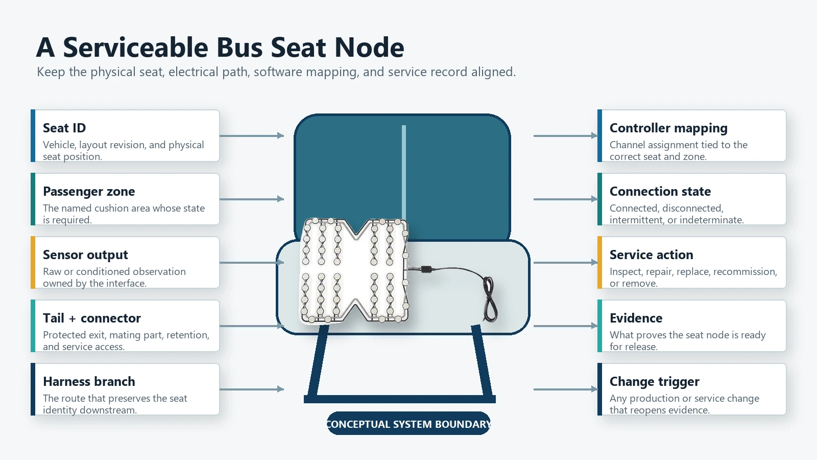
A fleet does not maintain an anonymous sensor. It maintains a particular seat in a particular vehicle, connected through a particular branch, with a known installation and replacement history.
Use one seat-node contract from the first drawing review:
| Field | Controlled question | Evidence needed |
|---|---|---|
| Seat ID | Which physical seating position does this record describe? | Vehicle layout, seat label, configuration record |
| Passenger zone | Where must a passenger load be observed? | Cushion section, zone drawing, datum map |
| Required observation | Contact, relative load, multiple zones, or another state? | Interface requirement and state table |
| Sensor output | What electrical evidence represents each valid state? | Circuit, pinout, sampled data |
| Harness branch | Which cable route and branch return this seat to the controller? | Harness drawing and branch label |
| Connection state | Can installed, disconnected, misconnected, and serviced states be distinguished? | Diagnostic and reconnection test |
| Cleaning exposure | How can liquid or contamination reach the sensor, tail, splice, or connector? | Cleaning method and exposure map |
| Service action | What may a technician inspect, disconnect, replace, or recommission? | Work instruction and access review |
| Fleet data owner | Who owns the seat-state record after it leaves the component interface? | System responsibility matrix |
| Evidence | What proves the installed node works as released? | Component, seat, bus, and fleet records |
| Change trigger | Which change requires review or retest? | Change-control plan |
This contract keeps the product drawing, seat drawing, harness drawing, controller mapping, service instruction, and data record aligned. Without it, the same electrical event can be interpreted as an occupied seat, a loose connector, a removed seat, or a mislabeled harness branch.
Separate Seat State From Passenger Counts
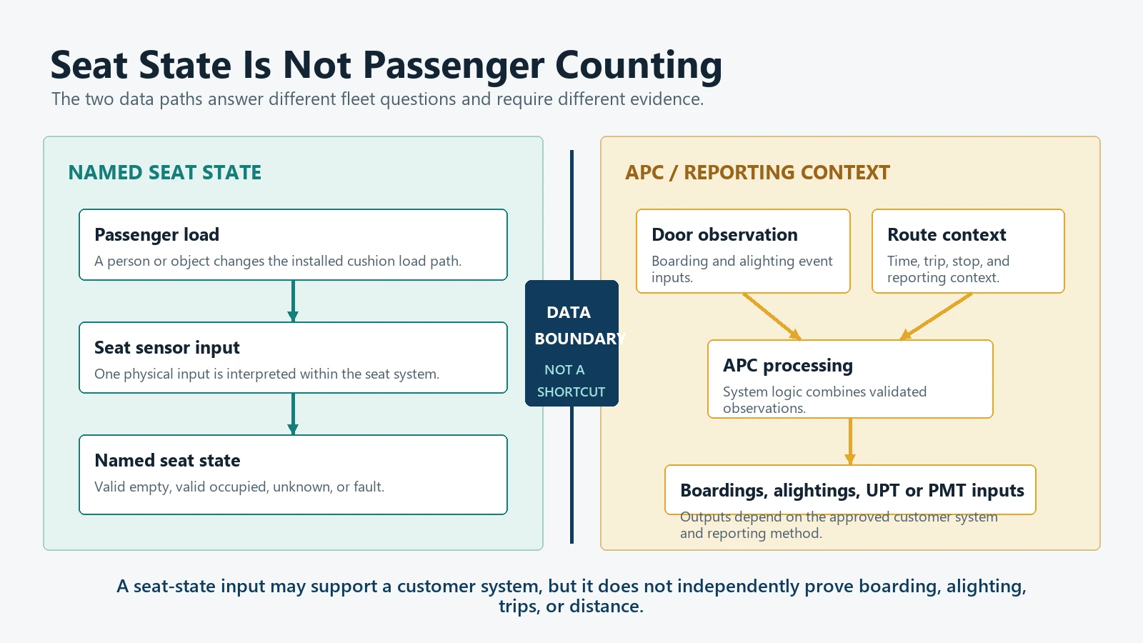
Seat occupancy and passenger counting answer different questions.
| Information | What it describes | What the seat sensor can contribute | What the seat sensor cannot establish alone |
|---|---|---|---|
| Seat state | Whether a named seating zone meets its approved occupied rule | A contact, relative-load, zone, or conditioned input | Boarding location, alighting location, trip identity, or travel distance |
| Boarding and alighting count | Passenger movements into and out of a vehicle | Customer-defined auxiliary context outside the APC measurement chain | A verified door event or complete passenger movement record |
| Unlinked passenger trip | A passenger boarding a transit vehicle | No direct trip record from one seat state | Whether one person boarded, transferred, or reboarded |
| Passenger miles traveled | Passenger movement over route distance | No direct distance record | Origin, destination, route segment, or miles traveled |
| Fleet utilization insight | How installed seating appears to be used over time | Time-stamped seat-state data if the fleet system owns it | Official reporting quality, approval, or completeness |
The Federal Transit Administration defines automatic passenger counters as devices that count passengers as they board and leave at stops. Its 2026 NTD Full Reporting Policy Manual treats unlinked passenger trips and passenger miles traveled as defined reporting measures. When APC-derived UPT or PMT data are used for NTD annual reporting, the APC data-collection method requires FTA approval and specified manual validation. That requirement should not be generalized to all automated fleet data.
A seat node may support a customer-designed availability display, occupancy map, operational study, or other fleet function. It should not be marketed as an APC system merely because several seats can report occupied or empty. A person can stand, change seats, place baggage on a cushion, leave a seat before reaching a stop, or remain aboard while the bus crosses reporting points. The fleet data owner must define any inference, validation, privacy, retention, and reporting rules beyond the physical seat state.
Give Each Seat a Stable Identity
Seat identity must survive installation, harness connection, controller mapping, maintenance, and replacement.
A useful identity chain is:
Vehicle identifier
  -> seating-layout revision
    -> seat position
      -> passenger zone
        -> sensor part and revision
          -> tail and connector
            -> harness branch
              -> controller channel or network object
                -> service and data record
Labeling only the controller channel is weak. A harness may be rerouted, a seat may be replaced, a branch may be connected to the neighboring position, or a configurable layout may change. The physical label, drawing, electrical map, software configuration, and maintenance record should point to the same seat.
The project should decide how identity is checked after assembly. A labeled branch, keyed connector, installation fixture, controller configuration, service scan, or controlled combination can make a wrong-seat connection observable before the fleet display assigns occupancy to the neighboring position.
For automotive and vehicle interface planning, keep the seat-node identity separate from the broader vehicle function. The sensor identifies its physical input path; the vehicle or fleet system owns the meaning and use of that input.
Name the Observation for Every Passenger Zone
An outline around the cushion is not a complete sensing requirement. Every required passenger zone needs a named observation.
| Zone question | Example requirement language | Design consequence |
|---|---|---|
| Coverage | Which cushion region must contribute to the state decision? | Active geometry, no-sense areas, datum control |
| Load transfer | Through which foam, trim, support, or plate does load reach the sensor? | Stack review and representative-seat testing |
| Exclusion | Which edge, frame, fastener, hinge, or service load must not create occupancy? | Keep-out zones and mechanical protection |
| Output | Does the system need contact, relative load, several zones, or a conditioned state? | Sensor architecture and interface circuit |
| Fault observation | Which open, short, intermittent, or disagreement conditions must remain visible? | Diagnostic ranges and channel design |
| Service observation | How will a technician identify the failed zone or path? | Pinout, branch mapping, test points, service record |
Wide bench seats, divided cushions, individual seats, tip-up seats, and priority seating can require different zone definitions even within one vehicle. Do not copy a mat shape between seats merely because the covers look similar. Foam contour, support ribs, cushion attachment, passenger posture, frame motion, and cable access may change the effective observation.
If several physical zones are combined into one electrical state, record where that combination occurs. It may occur in printed conductors, a connector, interface electronics, controller software, or a fleet application. A technician cannot diagnose a zone-specific problem if the design documentation pretends that the combined result came from one uniform area.
Match the Sensor Architecture to One Fleet Decision
Select the observation architecture after the fleet decision is defined.
| Architecture | Useful when | Main integration burden | Stop condition |
|---|---|---|---|
| Contact mat | A defined load condition can close or open a stable contact path | Load spreading, contact state, open/short distinction | Required empty and occupied conditions cannot remain separate |
| Analog pressure-related sensor | Relative signal carries useful margin or trend information | Measurement circuit, calibration, drift, thresholds | The project expects absolute weight without a suitable measurement chain |
| Multiple dedicated zones | Position or partial-coverage information must remain visible | More conductors, channels, identity, diagnostics | The controller cannot preserve zone identity |
| Shared or multiplexed zones | Conductor count must be balanced against several observations | Scan timing, crosstalk, mapping, fault isolation | A fault can create ambiguous states that the system cannot handle |
| Structural or frame measurement | Seat support load is more stable than cushion load | Mechanical structure, strain path, calibration | The required structure cannot be controlled across production and service |
| Non-seat APC device | The actual need is boarding and alighting data | Door geometry, passenger flow, validation, data approval | The project is trying to infer official passenger counts from cushion states |
The promoted product is not automatically the correct architecture. A fleet project may need only a simple seat-present input, a multi-zone state, a structural measurement, or a door-based APC system. Mixing those decisions creates a sensor that is expected to be thin, cheap, count people, estimate weight, locate posture, diagnose itself, and satisfy reporting rules at the same time.
Define the smallest observation that supports the approved action. Then allocate the physical sensor, interface electronics, controller logic, fleet software, and reporting ownership around that decision.
If the architecture is still open, share the seat section, required passenger zone, output type, tail direction, connector, and service access through the bus seat occupancy sensor project route. That review can determine whether a flexible mat is appropriate before the harness, controller mapping, and fleet-data assumptions become fixed.
Control the Load Path Through High-Use Seating
Fleet seating sees repeated use, but a generic cycle claim does not define the installed load path.
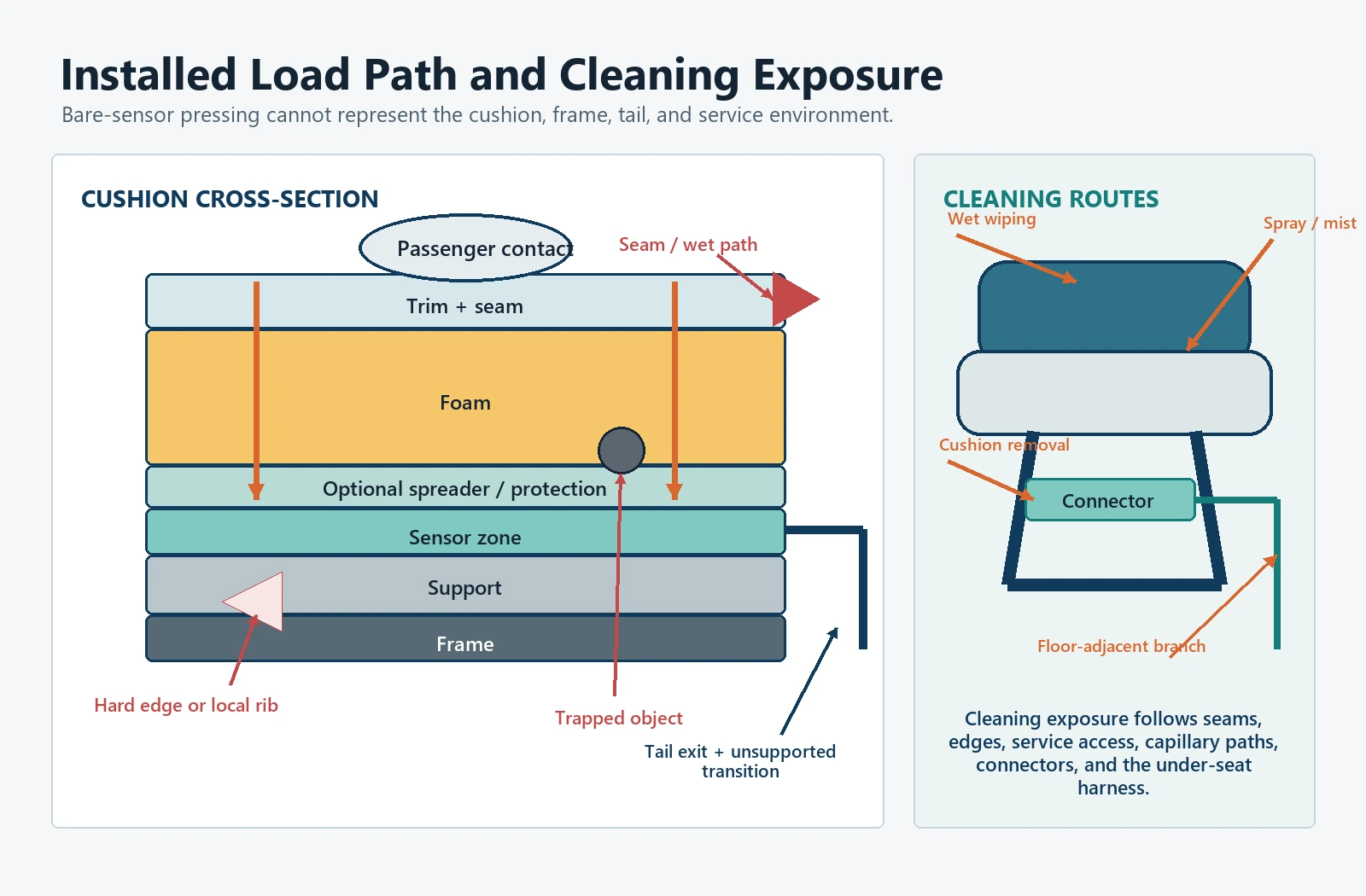
Map how load moves from the passenger to the sensor and into the seat structure:
Passenger contact
  -> trim and seams
    -> foam and local features
      -> load spreader or protection layer
        -> sensing zone
          -> lower support
            -> frame and attachment
Review the map in empty, occupied, edge-loaded, kneeling, leaning, twisting, and service conditions. The sensor should not become the unintended hinge, spacer, wear surface, or hard stop. Local ribs, frame edges, fastener heads, upholstery clips, and foam cutouts can create stress even when the average cushion load looks reasonable.
High-use design means controlling the failure path, not promising a universal life. Record where sliding can occur, where compression concentrates, where a folded cushion changes contact, and where the tail leaves the protected stack. If a protection layer is added, verify that it does not spread load away from the required zone or preload the sensor when the seat is empty.
Component pressing can screen construction. Only a representative installed seat can show whether the released cushion stack transfers the required passenger loads and rejects the non-passenger loads.
Route the Harness for Installation and Service
Harness routing should work for the assembler and the technician, not only for the finished CAD view.
Define:
- the sensor tail exit and supported transition;
- the route through foam, trim, seat pan, or frame;
- the first strain-relief point;
- clearance from sharp edges, pivots, springs, latches, and moving links;
- branch labels and connector orientation;
- service loop and access direction;
- retention during cleaning and cushion removal;
- allowable disconnect and reconnect procedure;
- separation from power, actuator, heater, or noisy cable paths where relevant;
- and the route after every seat adjustment or folded state.
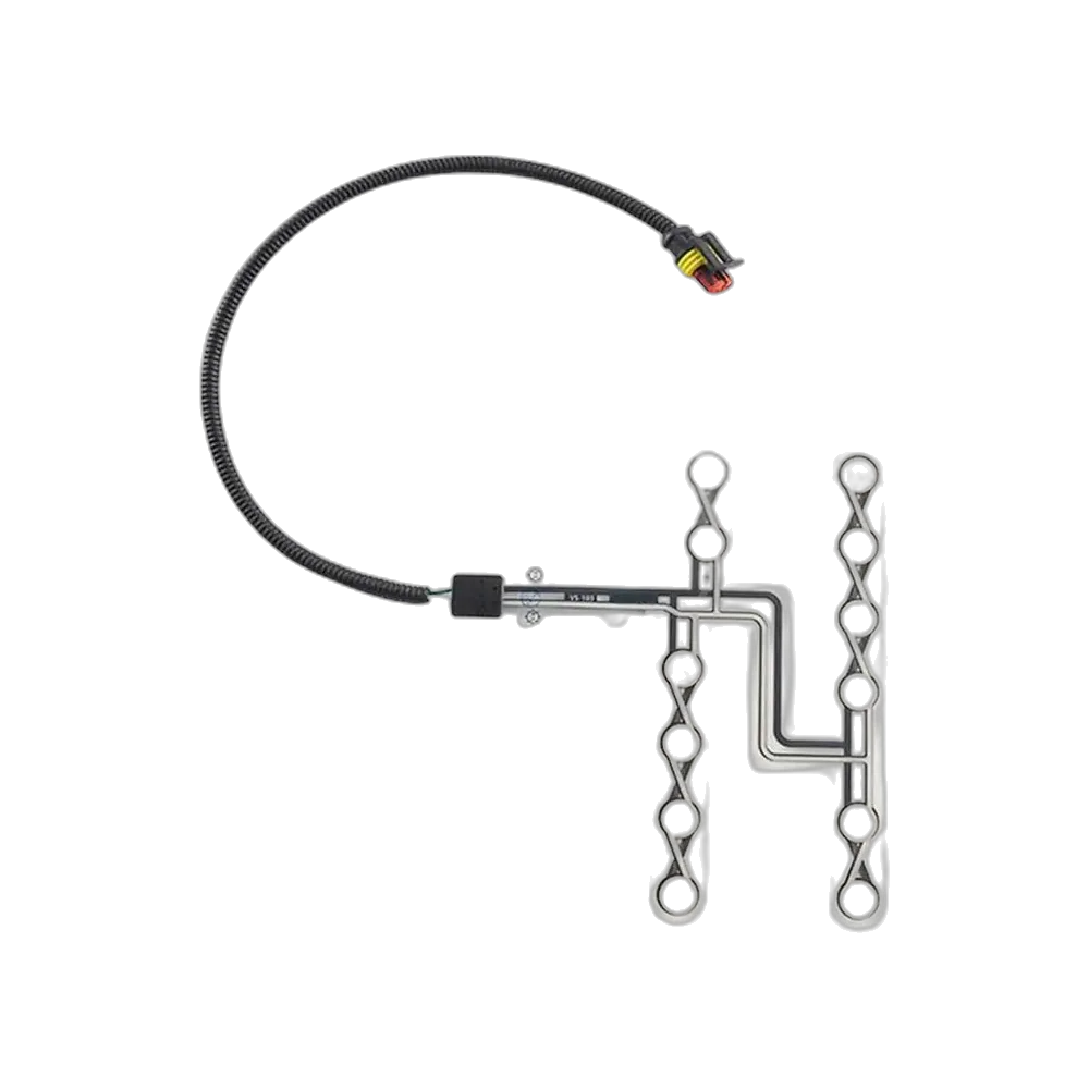
The printed-tail connector overview is useful for discussing tail termination at an early stage. It does not choose the final fleet connector, terminal, seal, retention, branch protection, diagnostic behavior, or vehicle qualification.
Installation photos should show the route before it disappears under trim. The harness drawing should identify supports, bends, branch breakouts, mating parts, and service access. Left-hand and right-hand routes should be controlled variants when they are not truly identical.
Protect the Tail and Connector at the Frame
The flexible sensing area may remain undamaged while the tail or connector fails at the seat frame.
Review four transitions:
- sensing zone to printed trace;
- printed trace to tail;
- tail to termination;
- connector to vehicle harness.
At each transition, identify bending, peel, rubbing, pull, unsupported mass, contamination, and repeated service handling. The tail should not be folded across an undefined edge, pinched between cushion and frame, used to pull the connector free, or left where a technician must push it aside to reach another part.
The interface specification should also state what a disconnected sensor looks like electrically. If open circuit is indistinguishable from a valid empty seat, a broken tail can silently remove an occupied position from the fleet view. If a diagnostic resistor or conditioned interface is used, assign its location, tolerance ownership, fault coverage, and replacement procedure.
Connector protection must match the actual location. A protected under-cushion connection, an exposed under-seat branch, and a floor-adjacent connection have different contamination and service paths. Do not assign a sealing label without mapping how fluid, dirt, and handling reach the mated connection.
Treat Cleaning as an Exposure Route
Cleaning is not one chemical test. It is a route by which liquid, residue, tools, and handling reach the seat node.
Create an exposure map:
| Entry point | Possible path | Possible observation | Design or service control |
|---|---|---|---|
| Seat surface | Seam or perforation into foam | Temporary load, residue, corrosion, changed foam behavior | Approved cleaning method and dry-state check |
| Cushion edge | Capillary path toward sensor or tail | Intermittent or drifting signal | Edge protection and drainage review |
| Frame and floor | Splash or wet wiping toward connector | Connector contamination or branch fault | Connector location, support, and inspection |
| Spray or mist | Deposition on exposed branch and mating surfaces | Leakage or residue | Application method and connector protection |
| Cushion removal | Tool contact, pulling, misrouting | Tail damage or wrong reconnection | Service instruction, labels, recommissioning |
Ask for the actual fleet cleaning process: liquid type, application method, dwell, wiping, rinsing, drying, seat position, and whether cushions are removed. The material list alone does not reveal where the fluid travels.
The component supplier can review material and construction compatibility within an agreed scope. The fleet or vehicle owner must approve the complete cleaning procedure and inspectability of the installed seat. A pass on a bare sensor coupon does not prove a connector below the cushion stays dry or that wet foam does not alter the seat-state decision.
Challenge the Design With Nuisance Loads
False detection should be investigated by physical case, not hidden with a long delay.
| Nuisance or non-passenger case | Why it matters | Evidence to capture |
|---|---|---|
| Bag, parcel, or service tool | Can resemble a localized passenger load | Raw input, interpreted state, position, recovery |
| Knee or hand during entry | Short high local load | Zone response and state qualification |
| Passenger leaning between seats | Loads an edge or neighboring zone | Seat identity and cross-seat response |
| Cleaning pressure | Repeated local force with possible moisture | Signal, connector state, post-cleaning recovery |
| Folded cushion or tip-up return | Changes preload and frame contact | State before, during, and after motion |
| Technician sitting on an unsecured cushion | Uses a non-production support state | Work instruction and diagnostic interpretation |
| Loose object trapped under trim | Creates persistent preload | Empty-state evidence and physical inspection |
| Harness movement | Produces intermittent electrical evidence | Raw samples, fault state, branch manipulation |
The customer decides which cases must remain empty, which may temporarily report occupied, which require unknown, and which should create a fault. There is no universal nuisance list or universal delay.
When a false state occurs, preserve the raw evidence and physical setup. Do not immediately tune the threshold. First decide whether the cause is a wrong zone, unstable load path, wet stack, trapped object, electrical intermittent, wrong seat mapping, or legitimate overlap between the approved cases.
Handle Tip-Up, Folding, Removable, and Priority Seats
Special seating changes the sensor’s mechanical state and the system’s expectation that a seat is available.
| Seat condition | Physical question | System question | Service evidence |
|---|---|---|---|
| Tip-up seat raised | Does gravity, hinge load, or cable motion affect the sensor? | Is the seat unavailable, empty, unknown, or separately reported? | Raised/lowered transition record |
| Folding seat moved | Does the fold create preload, rubbing, or a new bend? | When can a valid state return? | Motion, connection, and recovery check |
| Removable seat absent | Is the branch safely parked and protected? | Can intentional absence be distinguished from disconnection? | Configuration and branch record |
| Seat reinstalled | Are identity, orientation, connector, and route correct? | Must the node be recommissioned before use? | Installation and functional result |
| Priority seat | Do posture, mobility aid, companion load, or transfer behavior change the zone need? | What exact state supports the intended fleet function? | Application-specific observation set |
| Bench or shared cushion | Can each required passenger position remain distinguishable? | Is one combined state acceptable? | Zone and controller mapping |
Do not force a configurable seat into the same logic as a fixed seat. A disconnected removable seat may be an approved configuration, while the same electrical condition on an installed seat is a fault. The controller or fleet system needs configuration evidence before interpreting the sensor input.
Accessibility, passenger information, restraint, or operational functions require separate requirements and approvals. The presence of a seat sensor does not establish that any of those complete functions comply with a regulation or procurement specification.
Preserve Valid, Unknown, Fault, and Out-of-Service States
Fleet maintenance becomes unreliable when every non-occupied result is labeled empty.
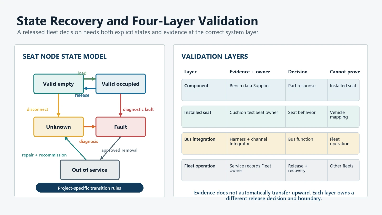
| State | Meaning | Allowed next step |
|---|---|---|
| Valid empty | The installed node has enough approved evidence for empty | Continue normal monitoring |
| Valid occupied | The installed node has enough approved evidence for occupied | Continue the assigned fleet or vehicle action |
| Unknown | Evidence is incomplete during startup, transition, reconnection, or revalidation | Wait, qualify, or follow the approved fallback |
| Fault | A defined electrical, logical, identity, or plausibility rule failed | Diagnose, record, and apply the approved fault response |
| Out of service | The seat or node is intentionally unavailable pending service or configuration | Prevent normal use of its data until release |
Unknown is not a convenient substitute for fault, and fault is not a convenient substitute for empty. Out of service is also different from an accidental disconnect. These distinctions allow the fleet system to avoid presenting false certainty and allow maintenance to prioritize a real failed node.
Define state recovery. A repaired connector may move from fault to unknown while the branch, identity, and sensor response are checked. Only then should it return to valid empty or occupied. If the software clears the fault as soon as voltage returns, it may miss a swapped connection, pin damage, or misrouted tail.
Make Diagnosis Seat-Addressable
A useful fault message identifies the seat and the observation path.
The diagnostic record should be able to answer:
- which vehicle and seating-layout revision were active;
- which seat and passenger zone were affected;
- which controller channel or data object represented that seat;
- which sensor, tail, connector, and harness branch were installed;
- what raw or electrical evidence was observed;
- which validity or fault rule changed state;
- whether the seat was fixed, folded, removed, cleaned, or being serviced;
- what action the technician took;
- and what recommissioning evidence allowed return to service.
Start at the reported seat and follow the identity chain toward the controller. Compare labels with software mapping before replacing the sensor, and inspect the load path and tail route before tuning logic. A broad seat sensor fault message loses the failure signature; a seat-addressable record can reveal clustering around a frame edge, cleaning route, branch design, connector location, or service action.
Recommission Every Replaced Seat
Replacement is not complete when the connector clicks.
Use a recommissioning sequence:
- Confirm vehicle, layout, seat, and part identity.
- Confirm the released cushion, sensor, protection layer, and installation revision.
- Inspect the seat surface, foam, support, tail, connector, branch, and frame route.
- Verify orientation, datum position, branch label, and mating connection.
- Confirm the intended configuration and controller mapping.
- Establish startup or unknown behavior.
- Verify valid empty, required occupied, release, and selected nuisance conditions.
- Check open, disconnect, or other approved diagnostic observations.
- Record the part removed, reason, evidence, replacement part, technician action, and result.
- Release the node only after the approved state and diagnostic evidence are complete.
The scope can be adjusted to the fleet program, but identity, installation, function, and record should remain tied to the seat node. A new cushion may alter the load path, while a correct sensor on the neighboring branch may pass a hand press but fail the seat map.
Turn Maintenance Records Into Engineering Evidence
Maintenance records are most useful when they preserve observations instead of only recording a replaced part.
Use consistent fields:
| Record field | Engineering value |
|---|---|
| Seat identity and layout | Locates the physical and configured position |
| Reported state and timestamp | Shows when the fleet first observed the event |
| Raw evidence or diagnostic code | Separates electrical, state, and data symptoms |
| Seat position and service condition | Shows folded, removed, cleaned, occupied, or empty context |
| Physical finding | Records pinch, rub, moisture, contamination, wrong route, loose terminal, or no defect found |
| Action taken | Distinguishes inspection, reseating, repair, replacement, remapping, and cleaning |
| Removed and installed revisions | Supports change and lot analysis |
| Recommissioning result | Shows whether the node returned to valid service |
| Repeat event link | Prevents repeated failures from looking unrelated |
Repeated replacement does not by itself prove a sensor-construction defect. The common factor may be a frame edge, branch route, connector location, foam change, cleaning practice, mapping error, or service action. Fleet records can guide a targeted engineering review, but they do not replace controlled validation because field observations are incomplete and collected under different conditions.
Validate Component, Seat, Bus, and Fleet Layers
Each layer answers a different question.
| Layer | Decision | Typical evidence | Boundary |
|---|---|---|---|
| Sensor component | Does the released part produce the specified electrical observations? | Drawing, continuity, zone, tail, connector, sample checks | Does not prove cushion behavior |
| Installed seat | Does the production-intent stack detect required loads and reject defined nuisance cases? | Representative seat builds, positions, motions, cleaning and service states | Does not prove vehicle mapping |
| Bus integration | Are seat identity, harness branch, controller channel, diagnostics, and configuration correct? | Vehicle layout, connection, state, fault, recovery, and mapping records | Does not prove fleet data quality |
| Fleet operation | Are maintenance, cleaning, replacement, records, and data use controlled? | Procedures, training, audits, service events, trend review | Does not convert seat state into official APC data |
Use the JASPER quality and testing page as a route for discussing drawing-based component inspection and project test planning. The actual installed-seat fixture, bus integration, environmental exposure, service simulation, sample plan, acceptance, external laboratory, and fleet trial must be confirmed for the project.
NIST measurement guidance separates repeatability, reproducibility, calibration, bias, stability, and uncertainty. That distinction helps a team locate variation in the sensor, cushion build, installation, fixture, operator, electronics, environment, or decision logic.
Use Bus Rules and Procurement Documents as Boundaries
Standards and agency guidance define responsibilities; they do not certify a seat mat by association.
APTA’s current Standard Bus Procurement Guidelines provide a common bus procurement framework that agencies can adapt to their project. Use that framework to identify interfaces, deliverables, configuration, maintainability, inspection, training, documentation, and acceptance responsibilities. Do not claim that a component complies with an entire bus procurement document unless the contracted clauses and evidence have been reviewed.
FTA guidance on monitoring operations and maintenance procedures describes observation, testing, inspection, audit, data review, and corrective action. It supports a controlled maintenance loop but does not prescribe a seat sensor, harness, threshold, cleaning method, or fleet-data design.
Under 49 CFR Part 625, transit asset management includes inventory, condition assessment, decision support, and investment prioritization for covered capital assets. A seat-node record may support local maintenance, but the regulation should not be described as mandating a sensor on every bus seat.
FMVSS No. 222 addresses school bus passenger seating and crash protection. It is not a generic transit-bus seat-sensor certification. The vehicle manufacturer must determine the vehicle category, applicable requirements, seat function, approval path, and evidence.
The official ISO 16750-3 and ISO 16750-4 listings can help frame mechanical and climatic questions for road-vehicle electrical and electronic equipment. The program still selects applicability, mounting location, severity, operating state, sequence, sample plan, and acceptance.
Lock Production and Service Changes
A fleet seat node can change without changing the sensor part number.
| Change | Possible effect | Evidence to reopen |
|---|---|---|
| Foam, trim, seam, insert, or cushion supplier | Load transfer, empty preload, wet behavior | Installed-seat states and nuisance cases |
| Sensor zone, trace, spacer, tail, or termination | Electrical observation, coverage, fault behavior | Component and installed-seat evidence |
| Protection layer, adhesive, tape, or mounting | Compression, shear, peel, drainage, service removal | Stack, assembly, and cleaning review |
| Frame, clip, hinge, latch, or seat mechanism | Rub, pinch, motion, access, false load | Route, motion, and service evidence |
| Connector, terminal, branch, or retention | Resistance, intermittency, identity, contamination | Pinout, diagnostic, handling, recovery |
| Controller circuit, threshold, filter, or mapping | State margin, timing, wrong-seat interpretation | Recorded-data review and bus integration |
| Cleaning product or procedure | Material exposure, liquid path, residue, handling | Exposure map and post-cleaning state |
| Seat replacement or layout revision | Identity, configuration, harness branch | Recommissioning and mapping |
| Maintenance instruction or tool | Tail damage, wrong disconnect, wrong route | Service trial and training evidence |
| Fleet data transformation | Meaning, completeness, privacy, reporting | Data-owner validation and governance |
Every change record should name the affected seat variants, owner, evidence to repeat, and release authority. No change to fit is not enough when a new foam, clip, cleaning route, or controller map can alter the observation.
Reject a Seat Mat When Another Architecture Fits Better
A flexible seat mat is a strong candidate when the required passenger state can be observed through a controlled cushion stack and the tail can be routed and serviced safely.
Use another architecture when:
- the actual requirement is door-based boarding and alighting counting;
- the system needs absolute passenger weight rather than a seat-state input;
- the seat structure offers a more stable and serviceable measurement path;
- required empty and occupied cases overlap after reasonable mechanical changes;
- a tip-up or removable seat cannot protect the sensing element and tail;
- the connector state cannot be distinguished from valid empty;
- the controller cannot preserve the identity of required zones;
- maintenance cannot reach or recommission the node without damaging the seat;
- cleaning exposure cannot be controlled or inspected;
- or the fleet does not have an owner for the resulting data and fault states.
The broader seat occupancy sensor product family can support a discussion of contact, pressure-related, and multi-zone directions. Selection should follow the required observation, installed load path, diagnostic need, and service model rather than the label on the product.
Prepare the Fleet Seat Sensing Package
Send one controlled package containing:
- Vehicle type, fleet use, seating layout, and seat identities.
- The exact fleet or vehicle decision supported by each seat state.
- A statement separating seat state from APC, trip, and passenger-mile data.
- Seat drawings, cushion sections, datums, moving states, and service access.
- Passenger zones, required observations, exclusions, and nuisance cases.
- Preferred contact, analog, multi-zone, structural, or other architecture.
- Electrical interface, circuit, valid states, unknown, faults, and recovery.
- Tail direction, route, support, connector, mating part, harness branch, and labels.
- Cleaning products, methods, liquid paths, drying, and inspection procedure.
- Folding, tip-up, removable, priority, bench, and replacement conditions.
- Component, seat, bus, and fleet validation responsibilities.
- Diagnostic, maintenance, replacement, recommissioning, and record fields.
- Applicable procurement, safety, environmental, and customer requirements.
- Prototype seat builds, vehicle access, fixtures, samples, data format, and review stages.
- Production volume, spare strategy, traceability, change control, and service horizon.
Mark every open item and assign an owner. The first engineering review should close the observation and interface before it discusses a production promise. If the project cannot define what one seat state means, no amount of extra sensor geometry will make the fleet data trustworthy.
Discuss a Fleet Seat Sensing Project
Share the seating layout, cushion section, passenger-zone map, sensor output need, tail and harness route, connector, cleaning process, configurable-seat states, fault model, service procedure, and validation responsibilities through the JASPER request-for-quote form. The review should first decide whether a flexible seat mat is the right observation architecture, then identify the component evidence JASPER can support and the installed-seat, bus, APC, regulatory, and fleet responsibilities that remain with the customer and system partners.
Sources
- JASPER Electronics, “Bus Seat Occupancy Sensor,” current product scope and engineering-input route. https://www.jasperele.com/products/car-seat-occupancy-sensor/bus-seat-occupancy-sensor/
Ready to Start Your Project?
Tell us about your membrane switch, keypad, or graphic overlay requirements. Our engineering team will review your specifications and provide a detailed quote.