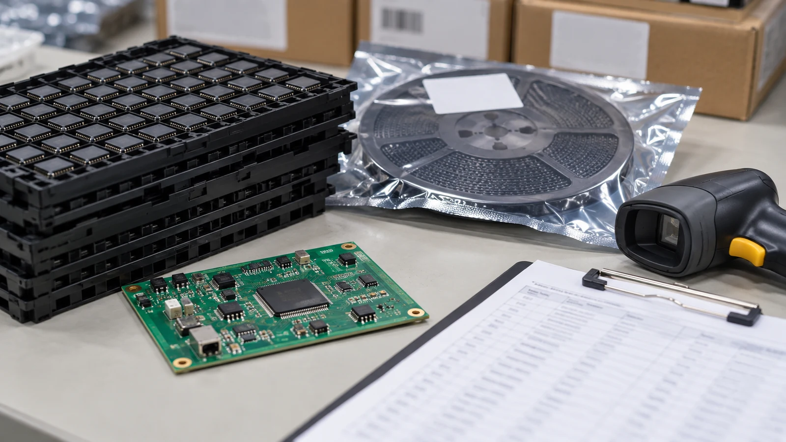
PCB assembly component substitution replaces a specified part with another manufacturer part number under controlled engineering approval. Approve the differences, verification results and affected build configuration before production use; a matching footprint or higher rating is insufficient. For the 3.3 V controller-rail example in this guide, use at least 2.2 µF effective output capacitance as a design reference target across the stated operating conditions. That target supports the circuit review; it does not authorize a replacement. Procurement approval, engineering approval and permission to place components must remain distinct.
- Define What Counts as a Component Substitution
- Compare Electrical, Mechanical and Process Requirements
- 1. Operating ratings and protection behavior
- 2. Effective capacitance and dielectric choice
- 3. Tolerance and the error budget
- 4. Package dimensions and pin functions
- 5. Thermal behavior on the actual board
- 6. Timing and analog dynamics
- 7. Firmware and programming interaction
- 8. Assembly and moisture handling
- 9. Lifecycle and source identity
- 10. Product obligations and approval scope
- Assign Engineering Approval Before Purchase or Placement
- Step 1: Open a controlled substitution request
- Step 2: Triage the differences and assign reviewers
- Step 3: Authorize samples and a verification plan
- Step 4: Review results and approve the exact scope
- Step 5: Release production purchasing and build instructions
- Step 6: Close the change against the built units
- Plan Verification for the Changed Functions and Risks
- Record the Approved Alternative in Controlled Build Data
- Handle Emergency Substitutions Without Losing Traceability
- Stop or Escalate These Eight Substitution Signals
- Prepare the Next Substitution Review
Define What Counts as a Component Substitution
A component substitution changes the part permitted at a specified reference designator, even when its nominal value and package name stay the same. Start the review with the complete manufacturer part number, including suffixes that identify voltage, temperature grade, package, finish or packing configuration. A distributor cross-reference is a candidate suggestion, not an approval record.
Buying the identical manufacturer part number through a different channel is primarily a source-control change. It still needs the agreed incoming and traceability checks. Selecting an alternative already released for the exact assembly revision is an authorized build choice within its documented conditions. Adding a new alternative requires engineering review.
Packaging-only differences deserve a narrower assessment: a change from reel to tray may leave the electrical design unchanged while affecting feeding, orientation, handling or lot tracking. Confirm what the suffix changes before deciding the review depth.
The cost of a poor substitution usually appears beyond the purchase order. A capacitor can pass incoming nominal-value inspection yet provide insufficient capacitance under DC bias. A memory device can fit the pads but fail the boot sequence. Reworking an assembled board then consumes engineering time, exposes components to another thermal cycle and complicates shipment segregation.
Avoid approving by component category alone. A resistor used as a pull-up and the same value used in a precision sensing path have different acceptance criteria. The approval unit is the part, circuit function, board revision and operating conditions. An alternative accepted at one location does not automatically become valid everywhere that original part appears.
Compare Electrical, Mechanical and Process Requirements
A component-substitution comparison must evaluate guaranteed limits, circuit behavior, physical fit and manufacturing requirements under the same conditions. Record the original requirement first. Then describe each candidate difference, assign verification and name the approval owner. A catalogue description such as “3.3 V, SOT-23” is not a complete specification.
Consider an illustrative replacement of TLV73333PDBVR with TLV75533PDBVR on a controller rail. Both use the five-pin DBV package, but the TLV733P family supports capacitor-free stability, while the TLV755P requires output capacitance. Its pin-table note requires effective input and output capacitance greater than 0.47 µF. The 300 mA versus 500 mA family ratings do not establish interchangeability.
Use this filled review matrix as an example of the decision logic. It describes a proposed comparison, not a qualified replacement.
| Comparison Area | Original Requirement | Candidate Difference | Verification Needed | Approval Owner |
|---|---|---|---|---|
| Electrical ratings | TLV73333PDBVR supplies 3.3 V at a 200 mA continuous system load | TLV75533PDBVR has a higher current rating and different external-capacitor requirements | Check operating limits, effective capacitance, startup and load response | OEM Electrical Engineering |
| Package and pinout | DBV five-pin footprint; IN 1, GND 2, EN 3, NC 4, OUT 5 | Candidate DBV pin functions match; dimensional tolerances and packing still require comparison | Overlay package drawings; check height, lands, orientation and feeder setup | OEM PCB Design and Manufacturing Engineering |
| Thermal behavior | Existing copper area and enclosure must support the 200 mA load | Candidate thermal characteristics and loss distribution require assessment on the same board | Calculate dissipation; evaluate junction temperature at worst operating conditions | OEM Electrical Engineering |
| Assembly compatibility | Released solder process and moisture controls apply to the original orderable part | Candidate finish, label restrictions and supplied packing become new build inputs | Review solderability, reflow exposure, handling and first-article joints | Assembly Manufacturing Engineering |
| Firmware interaction | Controller starts, resets and shuts down correctly on the existing 3.3 V rail | Changed rail ramp or discharge behavior can alter reset sequencing | Exercise startup, brownout, repeated power cycles and recovery with released firmware | OEM Firmware Engineering |
| Lifecycle and source | Purchased material must match the released MPN and approved source conditions | New MPN introduces separate supply, change-notice and lot records | Verify orderable identity, source documentation and incoming traceability | Procurement and Supplier Quality |
1. Operating ratings and protection behavior
Compare recommended operating conditions separately from absolute maximum ratings. Check voltage, current, leakage and fault behavior at the actual load and temperature. For MOSFETs, a lower on-resistance can arrive with higher gate charge and different switching losses.
Good signal: Electrical Engineering maps each stressed parameter to a circuit requirement. Red flag: The justification consists only of a higher voltage or current rating.
2. Effective capacitance and dielectric choice
For the worked 3.3 V rail, adopt 2.2 µF effective output capacitance as a conservative design reference target at 3.3 V DC bias and −40 °C to +85 °C local capacitor temperature, including initial tolerance and aging. Select a nominal value using the exact MLCC’s characteristics; a nominal 2.2 µF label does not prove this target.
The bounded dielectric options here are X5R and X7R. X5R specifies −55 °C to +85 °C and ±15% temperature change; X7R specifies −55 °C to +125 °C and ±15%. Start with X7R for temperature margin, then compare actual bias curves. These codes do not guarantee capacitance retention under voltage.
Good signal: The MLCC calculation covers the selected MPN’s bias, temperature, tolerance and aging. Red flag: A 25 V part is assumed equivalent to a 16 V part without checking capacitance at the operating voltage.
3. Tolerance and the error budget
Compare initial tolerance with drift, noise, offset and aging where they affect the function. Changing a sensing resistor from ±0.1% to ±1% can consume the measurement budget even if resistance and package match.
Good signal: The updated worst-case error remains within the circuit’s allocated limit. Red flag: Room-temperature nominal measurements replace a tolerance analysis.
4. Package dimensions and pin functions
Compare the manufacturer’s dimensioned drawing, land pattern and pin descriptions. Check exposed pads, no-connect instructions, connector keying and height clearance. Identical package marketing names can hide different details.
Good signal: PCB Design verifies every pin and relevant mechanical dimension against released CAD. Red flag: Approval relies on a distributor’s package-name filter.
5. Thermal behavior on the actual board
For a linear regulator supplied at 5.0 V, delivering 3.3 V at 200 mA, first-order dissipation is (5.0 − 3.3) × 0.200 = 0.34 W, excluding quiescent-current loss. A higher current rating does not remove that heat. Evaluate the package, copper, airflow and enclosure together.
Good signal: Junction-temperature assessment uses the application board and load. Red flag: A thermal-resistance value from a different test board is treated as a measured product temperature.
6. Timing and analog dynamics
Check propagation delay, edge rate, oscillator startup, reset thresholds and analog settling against interface requirements. A faster logic device can change ringing and emissions; a different regulator can change startup overshoot.
Good signal: Timing and waveform limits are defined before testing. Red flag: A single successful power-up is the complete dynamic assessment.
7. Firmware and programming interaction
For programmable or digital parts, review device identification, register behavior, boot modes, memory organization and programming support. Even an analog substitution can affect firmware through power sequencing.
Good signal: Firmware Engineering confirms operation with the released binary and records any required version change. Red flag: Compatibility requires an undocumented patch on the production programmer.
8. Assembly and moisture handling
Compare solder finish, reflow exposure, paste compatibility, inspection access and moisture sensitivity. The complete MSL set below shows why a moisture classification change can affect scheduling. The table states floor-life conditions at 30 °C; apply them with the selected part’s labeling and process requirements.
| Classification | Floor life after opening under the stated exposure conditions | Relative humidity |
|---|---|---|
| MSL 1 | Unlimited for this classification condition | 85% RH |
| MSL 2 | 1 year | 60% RH |
| MSL 2a | 4 weeks | 60% RH |
| MSL 3 | 168 hours | 60% RH |
| MSL 4 | 72 hours | 60% RH |
| MSL 5 | 48 hours | 60% RH |
| MSL 5a | 24 hours | 60% RH |
| MSL 6 | Bake before use; reflow within the label’s specified time | 60% RH |
Apply the actual component label and manufacturer handling instructions. A reflow classification peak is not an oven recipe, and this table does not prescribe a universal bake cycle.
Good signal: Manufacturing Engineering confirms the candidate fits the controlled process window. Red flag: The original moisture or thermal limits are copied without checking the replacement.
9. Lifecycle and source identity
Confirm the full orderable MPN, manufacturer, source conditions and applicable change notices. Keep sourcing evidence separate from functional equivalence: neither proves the other.
Good signal: Supplier Quality can connect incoming material to its procurement and lot records. Red flag: Generic descriptions replace manufacturer identity on the approval request.
10. Product obligations and approval scope
Check whether the component affects a customer-specific requirement, safety function or product qualification. A favorable datasheet comparison cannot expand an existing approval’s scope.
Good signal: Quality Engineering identifies required customer or product-level review before release. Red flag: One board variant’s approval is applied to every assembly using the part.
Assign Engineering Approval Before Purchase or Placement
The OEM’s designated design authority should approve component equivalence before production procurement or placement, unless the contract explicitly delegates that authority. Name that approver. Procurement owns commercial execution; Manufacturing Engineering owns process acceptance. A project manager can coordinate both decisions, but cannot replace the required design sign-off by accepting a delivery date. Use six steps to connect the decisions.
Step 1: Open a controlled substitution request
Record the original and proposed manufacturer part numbers, affected reference designators, assembly revision, quantity and reason for change. Attach both datasheets and the relevant circuit requirements. Procurement can initiate the request, but must identify the engineering approver and the production date affected. Preserve the original requirement while the request is open.
Step 2: Triage the differences and assign reviewers
Electrical Engineering leads the comparison and brings in PCB Design, Firmware Engineering, Manufacturing Engineering and Quality Engineering where their functions change. Classify the proposal as already approved within scope, suitable for evaluation, requiring redesign or unacceptable. A purchasing cross-reference does not satisfy this step. Identify coupled changes, including output capacitors, test limits and firmware.
Step 3: Authorize samples and a verification plan
Before ordering evaluation material, approve the sample quantity, source and test purpose. Block it from production. Define which engineering assemblies may receive it, and agree on acceptance limits before testing. If Procurement needs to reserve scarce inventory earlier, obtain separate commercial authorization covering cancellation or stock liability. That authorization does not approve engineering use or shipment.
Step 4: Review results and approve the exact scope
The design authority reviews the comparison and verification results. Manufacturing Engineering accepts process changes, and Quality Engineering obtains customer approval where required. State the approved MPN, circuit locations, assembly revisions and any conditions. Record unresolved failures as a hold or rejection. An approval email can be evidence, but its content must enter the controlled change record.
Step 5: Release production purchasing and build instructions
Configuration control releases the updated BOM or approved-alternative record and synchronizes affected instructions. Procurement then orders against that release. Before kitting or placement, the assembler checks the received MPN, lot restrictions, effectivity and manufacturing package against the approved decision, including any capacitor or firmware change that must accompany the alternative. Keep the build blocked if those records disagree.
Step 6: Close the change against the built units
Record which serial numbers or lots used the alternative and retain the inspection and test results. Reconcile unused material, exceptions and rework. For a permanent alternative, make the next order inherit the released configuration. For a temporary deviation, close or expire the permission explicitly. A future repeat order starts from the controlled record, not a remembered conversation.
Request -> Difference review -> Authorized evaluation -> Engineering decision
Engineering decision: pass -> Controlled release -> Build traceability and closure
Engineering decision: unresolved -> Hold -> Additional analysis or testing -> New decision
Engineering decision: fail -> Reject candidate -> Retain approved configuration
Plan Verification for the Changed Functions and Risks
Substitution verification should test the functions and failure mechanisms affected by the candidate differences. Begin with engineering analysis, then select bench, assembly and system checks that can expose the identified risks. Passing visual inspection or a continuity test cannot establish regulator stability, timing compatibility or long-term performance.
For the illustrative controller rail, a useful plan checks 4.75 V, 5.0 V and 5.25 V input, with load transitions between 20 mA and 200 mA. Select chamber conditions and soak time to exercise the declared −40 °C to +85 °C local capacitor envelope. Measure component temperature; do not assume it equals chamber air temperature.
For this example, set the steady-state rail requirement at 3.3 V ±3%, or 3.201 V to 3.399 V, and retain the 2.2 µF effective-capacitance design target. These are worked design requirements. Reject a settled rail outside those voltage limits. Define the controller’s transient voltage, reset threshold and power-sequence limits separately; a reading inside the DC window cannot establish that a short excursion is acceptable.
Capture startup at different input ramp rates, shutdown and brownout recovery. Record the load edge rate. Compare the 20 mA to 200 mA transition and its reverse on original and candidate assemblies using the same fixtures, firmware and probes, so an apparent improvement cannot be explained by a slower test stimulus. Check controller reset as well as rail voltage.
The assembly trial should check identity, orientation and joints using package-appropriate inspection. Include X-ray where hidden-joint risks justify it. Ask Electrical Engineering and Quality Engineering whether changed edges, switching behavior or construction require EMC, environmental or reliability testing. Functional acceptance and workmanship acceptance answer different questions.
Let failure consequence and process variation determine sample coverage. A few functional prototypes do not establish production reliability. The plan should state the units, lots, temperature conditions and repetitions required, plus the reason for that coverage. Archive instrument settings, raw results, failures, corrective actions and the signed disposition. A successful rerun must not erase the original failure or its explanation.
Record the Approved Alternative in Controlled Build Data
An approved alternative must appear in the controlled data used to purchase, assemble, test and identify the product. Link the change decision to its effective assembly configuration and built units. The approval is incomplete if engineering has accepted the candidate but purchasing or the placement line still works from an older release.
Keep the data responsibilities clear. The BOM identifies the selected parts and reference designators. The component placement list identifies position, rotation and board side. A BOM edit does not automatically update placement information, inspection libraries or test programs. The referenced supplier BOM and CPL guidance.
Apply the organization’s revision policy to the objects that actually change:
| Change outcome | Controlled record to release | Other build data to review | Repeat-order rule |
|---|---|---|---|
| Permanent alternative with unchanged board geometry | BOM or approved-alternative-list revision, linked to the engineering change | Purchasing identity, inspection recognition and test coverage | Use only within the recorded assembly revisions and conditions |
| Alternative requiring a different footprint or routing | PCB design revision plus affected assembly and BOM releases | Fabrication data, stencil, placement, inspection and fixtures | Order the matching board and assembly configuration together |
| Alternative requiring different firmware | Firmware release plus documented hardware compatibility | Programming files, version checks and functional test | Prevent incompatible hardware and firmware combinations |
| Temporary lot-specific alternative | Authorized deviation linked to the existing released configuration | Work order, material segregation and as-built record | Stop at the quantity or expiry limit; reapproval is required |
A purchasing-only MPN change does not automatically require new copper artwork. A footprint, routing or stack-up change does. Even without a PCB revision, a new permanent alternative needs a controlled authorization and effectivity; the exact BOM or list revision mechanism follows the company’s configuration system.
Effectivity answers which orders, board revisions, serial numbers or lots may use the change. Include the approver, decision date, evidence references and conditions. Preserve both the original approved definition and the new one. Record the part actually fitted, so a field return can be traced even when several alternatives were permissible at build time.
Handle Emergency Substitutions Without Losing Traceability
An emergency substitution should use an expedited, bounded deviation with the same named engineering authority and explicit release conditions. Schedule pressure can shorten the communication path; it cannot demonstrate electrical equivalence. Keep evaluation material, approved production material and rejected material distinguishable throughout the order.
For example, an OEM could authorize a candidate for one named work order covering 200 assemblies, valid until that quantity is consumed or the stated expiry date arrives, whichever occurs first. The deviation must identify exact original and replacement MPNs, affected reference designators, board revision, source and lot restrictions, completed verification, signatories and any extra production checks. The numbers illustrate scope control, not a JASPER order or a recommended test sample size.
If a temporary decision permits reduced verification, the designated authority must document the remaining risk and the contractual basis for release. Record what was omitted. Requirements tied to safety, customer approval or product qualification still apply, even when Procurement has already purchased the material or the assembly slot is booked. An incomplete necessary check leaves the build on hold.
At closure, reconcile the quantity built, serial or lot identifiers and remaining stock. Block automatic replenishment. If the 200-assembly authorization is exhausted, unused substitute components remain segregated until a new decision permits their use. Before the next order, complete permanent qualification, issue a new bounded approval or return to the original part. Repetition does not extend a deviation.
Stop or Escalate These Eight Substitution Signals
Stop production release when the candidate cannot meet a defined requirement or its permitted use cannot be controlled. Escalate questions that need design, quality or customer authority before treating them as purchasing choices. These eight signals override an attractive price or delivery date.
| Signal | Required disposition |
|---|---|
| 1. Pin functions conflict with the released circuit | Reject as a direct replacement; route any circuit change through PCB Design |
| 2. Recommended operating limits do not cover the application | Reject the proposed use or redesign the operating conditions |
| 3. Bias, tolerance or timing analysis exceeds the circuit budget | Hold for Electrical Engineering analysis and a suitable candidate |
| 4. Startup, transient or functional verification fails | Contain samples; investigate the failure before another approval decision |
| 5. Assembly limits conflict with the released process window | Hold for Manufacturing Engineering process assessment and trial |
| 6. Received manufacturer identity or lot evidence does not match the request | Segregate material and resolve with Supplier Quality |
| 7. Required customer approval or engineering authority is absent | Hold release until the designated authority acts |
| 8. A temporary approval has expired or cannot be tied to built units | Stop further use and reconcile effectivity and traceability |
A hold is an explicit work state. Give it an owner, the evidence required to clear it and a purchasing instruction. Without those details, an unresolved question can quietly become a line-side assumption.
Frequently Asked Questions
PCB assembly component substitution needs a decision tied to the application and a record that production can execute. These answers address the purchasing and engineering boundaries that most often cause uncontrolled changes.
Is matching the footprint enough to approve a substitute?
No. Matching the footprint only addresses part of physical compatibility. Engineering must also compare pin functions, operating limits, dynamic behavior, thermal performance and assembly requirements. The same land pattern can accommodate devices that behave differently or require different surrounding components.
Who should approve a component alternative in a turnkey order?
The OEM’s designated design authority should approve the alternative unless the contract explicitly delegates that responsibility. The assembler should confirm manufacturing compatibility, and Quality Engineering should obtain required customer approvals. Turnkey purchasing responsibility alone does not authorize changes to the product design.
Can a higher-rated component still be unsuitable?
Yes. A higher current or voltage rating can accompany different capacitance requirements, switching behavior, leakage or mechanical details. In the regulator example, the higher-current candidate still needs its external capacitors and startup behavior reviewed. Compare performance in the circuit rather than ranking isolated catalogue numbers.
When does substitution require a new board or BOM revision?
A new PCB design revision is needed when the substitution changes controlled board geometry, routing or construction. A permanent alternative also needs release through the BOM or approved-alternative system, even if the PCB remains unchanged. Firmware and assembly instructions need their own updates when affected.
How should an emergency substitute be documented for repeat orders?
Document it as a bounded deviation with exact MPNs, affected revisions, quantity or expiry limits, approvers, verification evidence and built-unit traceability. A repeat order requires a still-valid authorization. Close the temporary deviation, renew it explicitly or release a permanent alternative before further use.
Can the assembler buy substitute parts before engineering approval?
The assembler can purchase evaluation samples under explicit sample authorization with defined quantity, source and segregation. Production procurement should follow engineering approval and controlled release. If stock must be reserved earlier, obtain separate commercial authorization and keep the material blocked from production use until release.
How much testing does a component substitution require?
Testing should cover the changed functions, credible failure modes and application conditions. The design authority selects sample and lot coverage according to risk. A basic power-on check cannot establish dynamic compatibility or reliability, and a small engineering trial does not replace a justified production qualification plan.
What should a capacitor-substitution review verify?
Verify effective capacitance under operating bias, temperature, tolerance and aging, together with ESR, physical fit and circuit response. The worked 3.3 V rail uses a 2.2 µF effective-capacitance reference target. That example target is separate from the regulator’s device limits and does not approve any particular capacitor.
Does every substitution require customer approval?
Customer approval is required when the contract, controlled specification or product qualification requires it. Other changes can follow the organization’s delegated engineering authority. Define those boundaries before procurement, and retain the decision record even when a separate customer signature is unnecessary.
Prepare the Next Substitution Review
Prepare a substitution package containing the released BOM and assembly revision, original and candidate datasheets, affected reference designators, circuit requirements, source information and required build date. Add the difference matrix, proposed verification and the name of the person authorized to approve the change.
For a JASPER project, use the PCB assembly services page to frame the manufacturing discussion, and include the substitution policy with the RFQ or order package. State whether alternatives are prohibited, limited to an approved list or subject to written engineering review. Release the approved configuration before production placement, then preserve the actual fitted-part record for the next order.
Ready to Start Your Project?
Tell us about your membrane switch, keypad, or graphic overlay requirements. Our engineering team will review your specifications and provide a detailed quote.