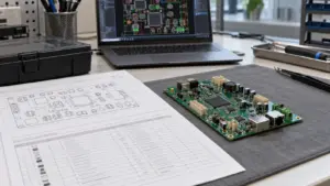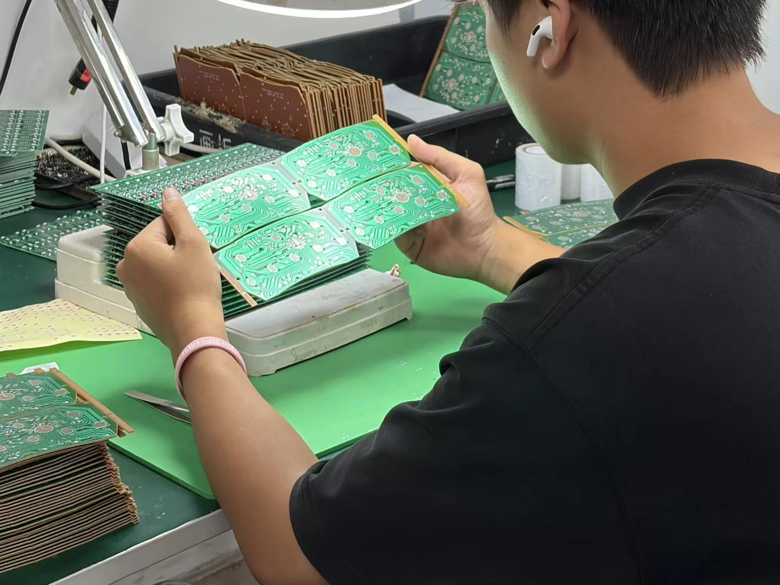
A PCB assembly pilot run is a controlled build used to decide whether a released design can be assembled, tested and repeated with the intended materials, tooling and work instructions. Approve scaling only when the run produces board-level evidence, verifies corrective actions and defines remaining limits. A functional pass or a repaired batch is not enough. Select build quantity and repeat tests from the risks and validation plan—not from a universal pilot-size rule—and keep shipment permission separate from production-process approval.
- What a Weak Pilot Decision Costs
- Set Learning Objectives Before the Pilot Build
- Evaluate the Pilot Against Ten Criteria
- Capture Assembly, DFM and Test Observations by Board
- Pilot learning checklist
- Define what the test actually covers
- Separate Design Issues from Process and Material Issues
- Assign Corrective Actions with Verification Evidence
- Issue-closure table: hypothetical worked records
- Close Prototype Feedback in the Pilot Report
- Decide What Must Be Repeated Before Scaling
- Choose the repeat scope from the change
- Set quantity from the claim, not a customary batch size
- Eight Signals That Block or Escalate Scale Approval
- Prepare the Pilot Review Package
What a Weak Pilot Decision Costs
A weak pilot decision commits the next build before the team understands what made the first build succeed. Consider a batch that passes only after an engineer adjusts a fixture, substitutes a component and repairs several joints. That batch may contain acceptable boards, but its final pass count cannot tell the buyer whether the released process is repeatable.
For the commercial review, separate planned assembly and test effort from debugging, sorting, rework, additional inspection and engineering supervision. Ask which activities remain in the proposed production route and which should disappear after verified corrective action. Otherwise, the quotation and delivery plan rest on different assumptions.
Lot acceptance and process learning answer different questions. NIST describes acceptance sampling as a decision about accepting or rejecting a lot, not as a method whose primary purpose is estimating its quality. A pilot review therefore needs more than a lot disposition: it needs an explanation of the process and its unresolved risks. NIST: acceptance sampling.
Set Learning Objectives Before the Pilot Build
Pilot learning objectives should name the uncertainty, the condition that exposes it, the evidence required and the person authorized to accept that evidence. Replace “confirm manufacturability” with a question such as “Can the connector be installed and inspected with the released bracket fitted, without manual realignment?”
Create a coverage plan around the intended production configuration. Include relevant board variants, panel positions, component sources, assembly operations, fixture versions and programming routes. Deliberately sample meaningful changes in conditions, such as a line restart or another trained operator. Do not claim coverage of an alternate material or manufacturing route that the pilot never exercised.
Record departures from the intended process before interpreting results. Engineering hand placement, special cleaning or temporary test leads may be useful for diagnosis; they cannot establish readiness for a different production method without a justified equivalence assessment or repeat build.
Define the sampling unit. A board, solder joint, panel, power cycle and test attempt are different observations. Repeating a test on one board does not create additional independently manufactured boards. Separate a learning sample chosen to expose a suspected mechanism from any randomly selected sample used for statistical inference.
The OEM design and quality owners should approve the failure definitions, confidence requirements where applicable, required operating conditions and acceptance limits before results are reviewed. The manufacturer should confirm the build route and evidence it will collect. Reserve material and time for verification, rather than spending the entire pilot allowance on the initial batch.
Evaluate the Pilot Against Ten Criteria
Evaluate a PCB assembly pilot run against evidence, not against the supplier’s confidence in the build. Use these ten criteria in the review. A good signal supports a specific conclusion; a red flag identifies a question that remains unresolved.
| Evaluation criterion | Good signal | Red flag |
|---|---|---|
| 1. Representative build conditions | The report identifies which intended materials, operations, variants and setup changes were exercised. | Hand-built demonstration boards stand in for an untried production route. |
| 2. Configuration control | Each board maps to the released fabrication, BOM, assembly, firmware and test revisions. | Mixed revisions or substitutions appear only in email comments. |
| 3. Assembly access | Installation, inspection, probing and necessary rework are demonstrated with the intended surrounding parts. | A connector fits only before a bracket or tall component is installed. |
| 4. Soldering repeatability | Results are linked to controlled stencil, paste, placement and thermal-profile records. | Repeated touch-up is treated as normal, without an identified mechanism. |
| 5. Material suitability | Exact fitted parts and relevant handling history are traceable; changes receive a technical assessment. | A nominally equivalent replacement is used without recording its package or operating differences. |
| 6. Test coverage | Required failure modes map to detection methods, access points, limits and retained results. | “Fully tested” means only that the board powers on. |
| 7. Measurement consistency | Check measurements address repeatability, operator or station differences and decision limits. | Passing depends on repeated reseating or the station used. |
| 8. Firmware configuration | Programming records identify the released image, settings and verification method for each board. | A filename is the only proof of what was loaded. |
| 9. Operator work instructions | Another trained operator follows the controlled instruction without undocumented engineering intervention. | The intended sequence exists only in one technician’s memory. |
| 10. Corrective-action closure | Verification exercises the corrected route and the original failure condition; an authorized reviewer accepts it. | A changed drawing or repaired board is treated as proof of prevention. |
For soldering, record the measured board profile rather than oven settings alone. Check relevant locations on each new design and respect solder-paste and component thermal limits. Use those measurements to establish the pilot process; there is no single reflow recipe suitable for every assembly.
For measurement consistency, investigate the measurement system separately from the product. NIST identifies repeatability, reproducibility, stability and bias as distinct concerns, including differences associated with operators, instruments and setup. A repeatable measurement can still be biased. NIST: gauge study issues.
Capture Assembly, DFM and Test Observations by Board
Board-level pilot records should preserve what happened before repair, what changed and what happened afterward. Assign a serial number or another unambiguous identifier before the first observation. For panelized work, retain the panel identity and board position as well.
Connect each record to the applicable revisions, fitted material lots, process settings, operator or station, inspection evidence, test-program version, measured values, limits and timestamps. Record the first result, every retest, any rework and final disposition. Describe a symptom precisely enough for another engineer to reproduce it.
Do not merge yield measures. For a named test stage and fixed cohort, define first-pass yield as boards passing at the first attempt without repair, adjustment or retest divided by boards entering that stage. Declare how invalid attempts are classified before calculating the result; retain every attempt. Reconcile final board dispositions separately. Rework is a history flag, not a mutually exclusive disposition: a reworked board can later be accepted, scrapped or held.
Pilot learning checklist
Use the following filled checklist to specify the evidence to collect. The root-cause owner coordinates investigation; the role assignment does not establish the cause in advance.
| Learning Area | Observation to Capture | Root-Cause Owner | Closure Evidence | Ramp Implication |
|---|---|---|---|---|
| Assembly access | Tool approach, connector mating, inspection visibility and clashes in the intended assembly sequence. | OEM mechanical engineer with manufacturing engineering. | Approved geometry or sequence change demonstrated on the intended assembly; review signed. | Do not extend the build while required operations depend on an undocumented workaround. |
| Soldering repeatability | Defect type and location, panel position, paste/stencil revision, measured profile and rework history. | Manufacturing process engineer with OEM design support. | Corrected process repeated on unreworked boards; targeted inspection and electrical results satisfy the approved plan. | Recurrence or unexplained concentration requires another process trial. |
| Material suitability | Fitted part identity, package fit, lot and handling history; behavior of approved alternatives. | Supplier quality and OEM component engineering. | Material assessment and relevant assembly/function evidence tied to the approved part and conditions. | An untested alternative remains outside the demonstrated scope. |
| Test coverage | Failure modes, accessible nodes, methods, limits, excluded functions and escape risks. | Test engineer with OEM system engineering. | Reviewed coverage map and approved challenge evidence showing required faults are detected. | A missing check for a scale-blocking failure prevents release. |
| Firmware configuration | Image identifier, settings, programming result, verification result and behavior after power cycling. | OEM firmware engineer with manufacturing test engineering. | Controlled programming record and specified configuration/function checks on affected boards. | Unknown programming state prevents a defensible disposition. |
| Operator work instructions | Sequence, orientation, handling, inspection decisions and steps needing verbal assistance. | Manufacturing engineering and production supervision. | Revised instruction demonstrated by trained operators; deviations resolved and training recorded. | Engineer-dependent operations need another controlled demonstration. |
Component clearance is more than whether parts overlap in CAD. The referenced supplier explains that the manufacturing courtyard also provides space for rework. Use the actual tooling and assembly context when resolving an access observation. The referenced supplier: component clearances.
Define what the test actually covers
Map the required fault spectrum to suitable methods: visual inspection, automated optical inspection (AOI), X-ray inspection, flying-probe testing, in-circuit testing (ICT) and functional testing are possible contributors, not a mandatory package. Record uncovered risks rather than assuming that adding methods proves complete coverage. The referenced supplier describes complementary testing around the faults each method addresses. The referenced supplier: complementary PCBA testing.
Use approved, non-shippable challenge samples or controlled simulations to check relevant detection paths where feasible. Identify what the challenge demonstrates and what remains outside it. A deliberately introduced fault must not re-enter saleable stock.
Separate Design Issues from Process and Material Issues
Pilot defect classification should separate the observed failure, its suspected origin and its consequence. A lifted component is an observation; “poor soldering” is not yet a root cause. The referenced supplier’s tombstoning guidance identifies layout-related thermal imbalance as one possible contributor, illustrating why a soldering symptom should not automatically be assigned to operator error. The referenced supplier: tombstoning.
Use five working origin tags: Design, Process, Material, Test system and Firmware/configuration. Mark an origin as suspected until evidence supports it, and allow multiple contributing causes. Keep the physical or electrical failure description unchanged when responsibility moves between teams.
Use a separate project disposition: Scale blocker, Controlled exception or Improvement. A scale blocker is an unresolved risk incompatible with the authorized next build. A controlled exception requires defined affected units, demonstrated containment, an owner, an expiry point and approval. An improvement is outside the agreed acceptance failure boundary but still deserves an accountable action. These are project review labels, not substitutes for contractual workmanship criteria.
Investigate by comparing controlled conditions. Examine whether a failure follows a component lot, board position, fixture, firmware version or operation. Change one factor at a time where practicable; use a documented experiment when interactions matter. A suspected test-system fault does not justify dismissing a product failure until the distinction is demonstrated.
Assign Corrective Actions with Verification Evidence
Corrective-action closure requires evidence that the change addresses the cause under the relevant conditions. Containment protects affected stock. Rework corrects an individual board. Corrective action changes the condition that produced the issue. Record these as different activities so that successful repair is not mistaken for prevention.
Use a controlled issue record containing the ID, affected boards, symptom, requirement, risk disposition, containment, cause evidence, action owner, due gate, change reference, verification plan, results and reviewer. The verification plan should define sample selection, conditions, acceptance criteria and related functions that might be affected by the change.
Use the states Open, Contained, Action implemented, Verification pending and Closed only when the corresponding evidence exists. When containment is unnecessary, record the reason rather than inventing an activity. Use Reopened when the issue recurs or a later change invalidates the accepted evidence. Assign a reviewer other than the action implementer where practicable, with authority appropriate to the risk.
Issue-closure table: hypothetical worked records
The records below illustrate completed entries, including unresolved decisions. Their identifiers and document references are fictional examples, not customer results or evidence from a JASPER build. For a live project, the reader supplies the actual identifiers, affected-board list, evidence references, responsible people and approvals.
| Issue and affected scope | Observation and cause evidence | Corrective-action owner and due gate | Verification evidence or remaining requirement | State and scale decision |
|---|---|---|---|---|
| P-01; revision-A connector installation | Bracket interference reproduced during the specified installation sequence; drawing review confirms the clash. | OEM mechanical engineer; release bracket revision B before the verification build. | Example closure packet: drawing B, fit-check record FIT-B and signed mechanical/quality review demonstrating the intended sequence on unreworked assemblies. | Closed for the verified revision-B configuration; revision-A stock retains its separate disposition. |
| P-02; boards with intermittent startup failures | Failure logs retained; affected stock segregated; cause remains unconfirmed. | OEM firmware engineer, supported by hardware/test engineers; resolve before scale authorization. | Repeat the recorded supply sequence and required operating conditions; identify cause, verify the correction and review related startup functions. No closure evidence exists yet. | Contained; scale blocked despite later successful boot attempts. |
| P-03; boards tested with fixture revision A | Contact instability reproduced at the fixture; affected test records identified; probes and support updated in fixture B. | Manufacturing test engineer; finish verification before releasing affected boards or extending the build. | Retain fixture change and diagnostic records; complete the planned measurement comparison, fault-detection challenge and disposition of affected earlier results. | Verification pending; fixture modification alone does not close the issue. |
An electrical pass cannot resolve every structural question. Electrical fault detection is different from verifying component alignment or physical solder-joint quality. When a functional pass is offered as the only evidence for closing an assembly defect, check whether the relevant structural condition was actually inspected.
Close Prototype Feedback in the Pilot Report
The pilot report should reconcile every relevant prototype DFM and test observation with its pilot evidence. Preserve the original issue ID and revision history. A design change without a manufacturing demonstration, or a test-script change without detection evidence, remains an action rather than an accepted conclusion.
Use this six-step review and handover process:
- Reconcile the issue register. The project lead imports prototype DFM, assembly and test feedback, links duplicates without losing history and assigns every retained issue an owner and verification route.
- Confirm the as-built scope. Manufacturing engineering identifies the boards, revisions, materials, operations and deviations actually represented. The report explicitly excludes configurations not built or assessed.
- Reconcile the board results. Quality and test engineering check first results, retests, rework and final dispositions against the board register. Every unexplained result receives an issue or a documented investigation reference.
- Review cause and action evidence. Design, process, material and test owners distinguish confirmed mechanisms from hypotheses and verify that released changes match the corrective actions.
- Review verification and exceptions. The authorized reviewers accept supported closures, define any bounded exception and identify repeat work. Each exception names its scope, containment, owner and expiry point.
- Authorize the next decision. The OEM release authority records the permitted configuration, remaining limits and signatures. Send those conditions to the team planning the subsequent production ramp; do not substitute a delivery date for technical approval.
The handover packet should let another engineer trace any conclusion back to an issue, affected boards, the applied change and the verification result. Retain unsuccessful tests as well as the accepted verification run. Approve shipment of specific boards separately from permission to repeat or extend the manufacturing process.
Decide What Must Be Repeated Before Scaling
Repeat pilot work when the original evidence no longer represents the corrected design, process or test method, or when it does not address the failure mechanism. Select the smallest justified repeat scope that answers the question while checking relevant interactions. Repeating only the repaired unit is insufficient to demonstrate a corrected manufacturing process.
Choose the repeat scope from the change
| Review outcome | Suitable evidence condition | Required boundary or next action |
|---|---|---|
| Proceed to ramp planning | Required learning objectives are satisfied, blocking issues are closed and the demonstrated configuration is controlled. | Transfer approved evidence and limitations; determine subsequent volume steps separately. |
| Conditional bounded build | Residual risk is acceptable to the authorized owner and containment is demonstrated for a defined scope. | Specify permitted units/configurations, monitoring, stop conditions and an expiry point; do not imply unrestricted approval. |
| Repeat a targeted subset | The cause and change are bounded, unaffected evidence remains applicable and relevant interactions can be evaluated. | Repeat affected operations or tests on representative units; include checks for unintended effects. |
| Repeat the complete pilot | Traceability is unreliable, several changes interact, the route changes materially or prior results cannot support the decision. | Establish a controlled configuration and repeat the required learning plan before approving scale. |
For a test-only change, first establish the revised method’s validity, then determine whether retained boards can support retesting. For a footprint, stencil or soldering change, require fresh assemblies made with that change. For firmware or part substitutions, check the affected operating states and interfaces rather than repeating only the easiest functional sequence.
Define retest conditions before seeing the result: board condition, power history, fixture, software versions, stimulus, load, environment, limits and permitted attempts. Preserve failed and invalid attempts. Investigate an intermittent failure instead of testing repeatedly until a pass appears.
Set quantity from the claim, not a customary batch size
An illustrative statistical objective shows why quantity needs a defined claim. Suppose the approved plan seeks a one-sided 95% upper confidence bound below 1% for one specified, detectable board-failure probability under fixed conditions. Assume the detection method identifies every occurrence of that defined failure. With zero failures on independent, representative boards, the exact binomial upper bound is:
p_upper = 1 - 0.05^(1/n)
The minimum integer sample is 299 boards; the bound is approximately 0.997%. This is a calculated example, not a recommended pilot quantity, a universal acceptable defect rate or a reliability qualification. NIST: exact binomial confidence limits.
The binomial model assumes a fixed probability across trials. Correlated observations, mixed configurations or changing conditions can invalidate the simple interpretation. A representative learning build may also need deliberately chosen conditions that should not be pooled as though they were one homogeneous random sample. NIST: binomial distribution.
Eight Signals That Block or Escalate Scale Approval
Scale approval should stop or move to the authorized risk owner when any of the following signals appears. Investigate the affected scope before deciding whether to contain, repeat or reject it; a final pass count does not resolve these signals.
- A safety-related failure or other designated critical failure remains unexplained.
- Required inspection or test coverage is absent or its detection path is unverified.
- The team cannot reconstruct which hardware, material or firmware configuration was tested.
- An intermittent failure disappears only after reseating, repeated testing or undocumented adjustment.
- The same defect returns after its corrective action was declared complete.
- Required operations depend on engineering assistance missing from the controlled instructions.
- A material, supplier, fixture or process change makes the existing evidence inapplicable.
- A deviation lacks an accountable owner, demonstrated containment, authorized scope or expiry point.
Frequently Asked Questions
Pilot-build decisions depend on what the evidence demonstrates and which conditions it represents. These answers distinguish closure, shipment and authorization for the next build.
What should a pilot PCBA build prove before production ramps?
A pilot PCBA build should demonstrate manufacturability, testability and repeatability for the intended configuration and agreed conditions. Its report should connect board-level results to material, process, firmware and test revisions. Blocking issues need verified closure, and any remaining exception needs an authorized scope, containment and expiry point.
How should prototype DFM feedback be tracked to closure?
Keep each prototype DFM issue under a persistent identifier linked to affected revisions, boards and evidence. Assign an owner, corrective action and verification plan. Close the issue only after the changed design or process has been demonstrated under relevant conditions and accepted by the authorized reviewer.
Does a passing functional test mean all pilot issues are closed?
No. A functional pass supports only the functions and conditions covered by that test. It does not automatically resolve structural defects, access problems, traceability gaps or measurement instability. Close each issue against its own acceptance requirement and verification evidence, preserving the original failure and any repair history.
When should part of a pilot build be repeated?
Repeat a targeted part when a bounded change invalidates specific evidence while other results remain applicable. Define the affected operations, representative units, original failure conditions and related functions to check. Use fresh assemblies for manufacturing changes; retained boards may support test-only verification when their condition remains suitable.
Which open issues can block scaling even if boards can ship?
Unexplained critical failures, missing detection coverage, uncontrolled configurations, recurring defects and ineffective containment can block scaling. A shipment decision applies to identified boards under defined acceptance conditions. It does not establish that future units can be produced by the same route without the unresolved problem recurring.
How many boards should a PCB assembly pilot run include?
Set quantity from the risks, represented conditions and validation claim, not a universal batch-size rule. The article’s 299-board example applies only to zero specified failures and the stated one-sided 95% confidence objective below 1%, under binomial assumptions. Repeated tests on one board do not provide independent board samples.
Can reworked boards be included in pilot evidence?
Yes, but identify them separately and state what they demonstrate. Reworked boards can support repair evaluation and some functional investigations, subject to their condition. They should not replace unreworked assemblies when evaluating the corrected manufacturing route. Preserve their original failures, rework steps, subsequent results and final dispositions.
Who should approve issue closure and the pilot decision?
The responsible technical owner should provide cause and verification evidence, and the authorized reviewer should accept closure. The OEM release authority should approve the next-build scope with quality, manufacturing and relevant design input. Separate the action implementer from the reviewer where practicable, especially for higher-risk issues.
Is an approved deviation the same as a closed issue?
No. A deviation authorizes a defined exception; closure demonstrates that the issue has met its verification requirements. Record the exception’s affected units, configuration, containment, owner and expiry point. Keep corrective action visible until verified, and reassess authorization whenever the conditions supporting the exception change.
Prepare the Pilot Review Package
Prepare the pilot review package around the decision you need: which configuration can move forward, which issues remain and what evidence will close them. Bring the controlled build data, as-built board register, prototype feedback log, learning checklist, original test results, rework history and issue-closure table to the review.
Agree the permitted next-build scope, verification work and release authority before committing further material. Keep subsequent ramp quantities and timing in a separate production plan, using the pilot’s verified boundaries as its inputs.
For a JASPER enquiry, share the board files, BOM, interface requirements and proposed pilot evidence package through the PCB assembly services route. Define the assembly, programming, inspection and test scope for the actual project. Ask for a reviewable pilot report—not just a promise that the boards will work.
Ready to Start Your Project?
Tell us about your membrane switch, keypad, or graphic overlay requirements. Our engineering team will review your specifications and provide a detailed quote.