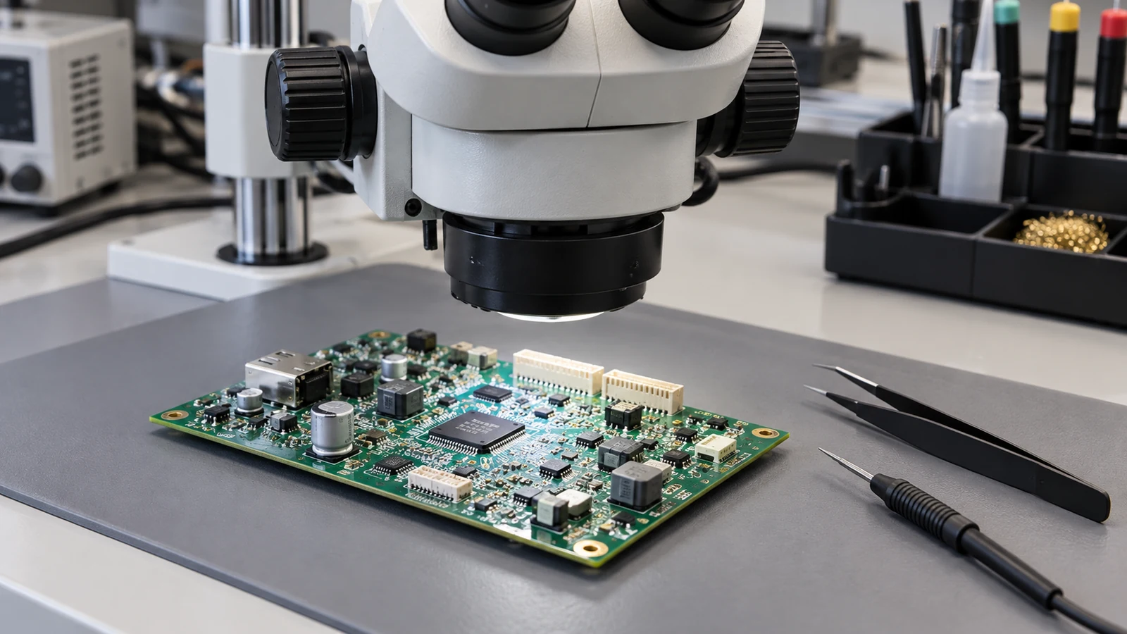
PCB assembly component clearance is the usable space around and above a mounted part that allows manufacturing, inspection, rework, and final installation without interference. There is no single minimum gap for every component. Define each clearance against maximum package dimensions, the actual tool envelope, component height, and process tolerances. Release the layout only when the intended placement sequence, inspection method, rework path, and connector or enclosure operations have a documented access route. A visible gap between two nominal component outlines is not enough.
- Define Clearance for Placement, Inspection and Rework Separately
- Check Component Bodies, Nozzles and Placement Access
- Read the dimension, not just the package name
- Protect Optical Views and Hidden-Joint Inspection Paths
- Reserve Rework Tooling and Heating Access
- Treat the tool as a moving volume
- Confirm heating access and replacement access
- Review Edge, Connector and Final-Integration Keepouts
- Resolve Clearance Exceptions with the Actual Assembly Process
- Apply Package Specifications and Assembly Standards Correctly
- Five Component-Clearance Review Scenarios
- A QFN beside a tall power inductor
- A BGA beside a shield frame
- An edge connector in an assembly carrier
- A latched harness connector inside an enclosure
- A double-sided board on a rework fixture
- Prepare the Clearance Review Before Layout Release
Define Clearance for Placement, Inspection and Rework Separately
Component clearance should be reviewed as several separate access requirements, not one distance in the CAD rules. Placement concerns delivery and release of a component; inspection concerns the required view or measurement; rework concerns removal and replacement on an already populated board. Final integration introduces mating parts, fixtures, and installation tools. This review addresses physical process access; electrical isolation spacing remains a separate design requirement.
Distinguish body-to-body spacing from land-pattern separation, manufacturing courtyards, and three-dimensional process keepouts. The referenced supplier distinguishes maximum component boundaries from placement courtyards and includes hardware and mating considerations in its clearance guidance. Its published values belong to its service conditions, not to every assembly process.
A courtyard is a useful screening boundary, but its usefulness depends on what the library author included. Do not assume it represents a hot-air nozzle, an angled camera view, or a connector-release tool. Record those requirements as separate geometry when necessary.
| Access Requirement | Geometry to Check | Tool or Process | Evidence Needed | Exception Review |
|---|---|---|---|---|
| Placement nozzle access | Maximum body and lead outline; nozzle tip, shank, and approach path; neighboring heights | Selected pickup nozzle and placement sequence | Package drawing, tool geometry, populated-state collision review | Confirm nozzle suitability and sequence on the intended equipment |
| Optical inspection view | Joint location, neighboring height, camera view, and illumination path | Actual AOI program or defined visual method | Images showing the required features in the intended assembly state | Demonstrate another qualified view or inspection method |
| Rework nozzle access | Nozzle exterior, heater approach, removal lift, shields, and underside support | Selected rework station and replacement procedure | Tool drawing, access trial, thermal profile, and post-rework inspection | Qualify the complete removal-and-replacement process |
| Connector mating access | Plug shell, latch movement, insertion stroke, cable exit, and removal path | Mating connector and assembly tooling | Mating-part CAD, tolerance review, and assembly trial | Obtain mechanical-owner approval for an alternate sequence or tool |
| Edge and fixture clearance | Overhangs, clamps, conveyor engagement, support contacts, and separation-tool path | Actual carrier, holder, and separation operation | Fixture drawing and populated-board handling review | Approve a defined fixture change or relocate the obstruction |
| Final-integration access | Enclosure opening, fasteners, driver sweep, board insertion, and service withdrawal | Product assembly and service sequence | Enclosure CAD and installation trial | Confirm assembly order, fastening, and service requirements together |
Use the matrix to assign evidence, not merely to label a layout compliant. One component can pass placement and fail inspection or rework. Keep those decisions separate in the release record.
Check Component Bodies, Nozzles and Placement Access
Placement access must accommodate the largest permitted component envelope and the selected pickup tool throughout its movement. Check the tool above neighboring parts as well as beside them; a narrow nozzle tip does not describe the complete shank or holder. Evaluate rotation, descent, release, and withdrawal in the intended population sequence.
Start from the exact manufacturer part number and package drawing. Include projecting terminals, housing tabs, permitted body dimensions, and installed orientation. Align component and tooling models to the same board datum. Add placement offset and rotation to a nominal model, or use an already expanded worst-case model; do not count the same dimensional allowance twice.
Read the dimension, not just the package name
For the TPS62130 family, drawing RGT0016C specifies a nominal 3 mm square VQFN: 2.9–3.1 mm body dimensions in both axes and 0.8–1.0 mm height from the seating plane. Check collisions using the maximum outline. Relate the seating plane to the assembled board; package height alone is not the full installed stack.
The examples below describe different objects and manufacturer-specific limits. They are not interchangeable spacing recommendations; read each value against its stated datum and function.
| Published example | Dimension and reference | Correct clearance use | What it does not establish |
|---|---|---|---|
| RGT0016C VQFN | Body 2.9–3.1 mm in each axis; package height 0.8–1.0 mm from seating plane | Build the maximum package envelope and locate it in the assembled stack | Placement accuracy, nozzle size, or an acceptable neighboring gap |
| N51-14 hot-air nozzle | Catalog designation 12 × 12 mm; tip drawing has a 13 × 13 mm square callout | Read the drawing rather than using the catalog designation as a collision box | Complete holder geometry, manufacturing tolerance, or thermal compatibility |
| VT-S1080-V3-R10 inspection system | Published clearance 50 mm above and 50 mm below the board surfaces; height measurement range 25.4 mm | Separate transport-envelope checks from measurement-range checks | Visibility of every joint within either envelope |
The N51-14 tool drawing shows an outer outline larger than the dimensioned square. Obtain complete tool geometry at each relevant height before approving a neighbor’s position. A catalog package-size label cannot define that missing envelope.
For a centered, unrotated pair of these RGT0016C packages, using the 3.1 mm maximum instead of the 3.0 mm nominal width moves each facing edge 0.05 mm into the gap. The nominal body gap loses 0.10 mm before placement errors or tools are considered. Rotation changes the projected outline and needs a separate check. This body-tolerance calculation neither approves a gap nor replaces tool-path review.
Check pickup suitability separately. Clearance does not prove that a nozzle can hold the part, protect a delicate top surface or release it repeatably. Validate placement accuracy and the equipment’s vision method as part of the actual assembly process.
Protect Optical Views and Hidden-Joint Inspection Paths
Inspection clearance must preserve the features and views needed to make an acceptance decision. A component fitting inside an inspection machine does not establish that neighboring joints are visible. Review the board in the population state that will actually be inspected, including shields and tall parts already installed.
The VT-S1080-V3-R10 specification distinguishes board clearance from its smaller height-measurement range. Mechanical passage and inspection coverage therefore require separate checks. Neither range alone qualifies a particular solder-joint view.
For an optical review, identify the joint feature first: an exposed lead, termination, polarity mark, or other required feature. Then establish whether the selected camera and lighting can see it. Inspect from the required directions rather than assuming that an unobstructed top view proves access from an oblique view. Capture representative images of the critical neighborhood and keep them with the inspection-program revision.
Increasing the gap around QFN, SON or BGA packages does not make their hidden joints optically visible. Transmission X-ray is an inspection option for concealed connections. Select the method for the joint and acceptance question; a larger optical keepout cannot replace an appropriate inspection method.
X-ray access also needs a defined setup. Identify the required board orientation, tilt or motion where applicable, and holder interference; evaluate the resulting images for the required feature. Do not assume that selecting an X-ray machine eliminates access review. Record inspection limitations against specific features and resolve them before approving the layout.
Reserve Rework Tooling and Heating Access
Rework clearance must support the complete replacement operation on a populated assembly. Space to pick up a new component during original production is not evidence that a heater, removal tool, cleaning tool, and replacement process can reach the same location later.
Review rework in order: secure the board, apply localized heat, lift the failed part, prepare the lands, apply replacement soldering materials, align the new component, reflow and inspect. For the LLP rework example, component-side paste printing in a separate fixture is an alternative to printing directly onto a crowded board; qualify the chosen route.
Treat the tool as a moving volume
Model the hot-air nozzle exterior, its height above the target, the vacuum pickup, and the removal lift. Include a tilted approach only when the proposed process permits it. Reserve space for protective shields and for the operator or mechanism to position them without touching adjacent components.
A tool can clear a low resistor yet interfere with a taller neighboring inductor at the same horizontal gap. Review the entire vertical profile rather than expanding every footprint by the same number. Also check whether a removed component can leave the site without crossing an obstruction.
Confirm heating access and replacement access
Mechanical clearance does not establish a safe thermal process. For QFN rework, profile the actual board and review separation from temperature-sensitive neighbors. Verify target joints and affected adjacent parts under the selected profile. The hot-air station setting is not the joint temperature.
Check the underside heater and support arrangement on double-sided assemblies. A clear top-side footprint can still leave no usable support or heating arrangement below it.
Finally, demonstrate land preparation and replacement. A smaller removal nozzle cannot solve an inaccessible replacement-stencil operation. When the process changes to component-side printing, dispensing, or another controlled method, qualify that method instead of assuming it produces an equivalent result. Rework approval should identify the method that was actually demonstrated.
Review Edge, Connector and Final-Integration Keepouts
Edge and final-integration keepouts must account for the equipment and mating parts that approach the board after component placement. Review the populated board inside its carrier and enclosure, not only as an isolated PCB outline. Static fit is only one stage of the installation check.
At the board edge, identify connector overhangs and the actual engagement zones of rails, clamps, holders, and separation tools. The referenced supplier warns that overhanging components can interfere with handling and panel separation. Its process-specific routing dimensions are not a substitute for the fixture and separation method selected for another build.
For connector mating, include both connector halves. Model the insertion direction and full engagement stroke, latch operation, cable exit, and withdrawal path. Check whether a release finger or defined tool can reach the latch after installation. For a forceful mating operation, define how the board is supported rather than allowing the adjacent components to become unintended load points.
Keep driver and fastener access separate from connector fit. A screw head can fit while the driver cannot approach squarely. Review board insertion, fastening, harness attachment, and enclosure closure in the intended order. Where service replacement is required, reverse the sequence and verify the withdrawal route as well.
Send a fixture supplier the populated three-dimensional envelope, relevant datums, and the permitted board-contact areas. Require the proposed fixture drawing to return those interfaces explicitly. “Keep parts away from the edge” is not a usable fixture specification. Coating-mask design and electrical test-probe access require their own reviews; they are not replaced by this assembly-access check.
Resolve Clearance Exceptions with the Actual Assembly Process
A component-clearance exception should be approved only for a defined layout, population variant, equipment configuration, and demonstrated process. An engineering waiver is not evidence that the operation works. Identify which access requirement fails, what will change, and what evidence closes that specific failure.
Use this release path: identify the affected reference designators → align maximum component and tool envelopes → review the complete process route → demonstrate the critical operation → record the disposition and approvals → control the released configuration.
Before an exception trial, agree on the representative population, selected tools, absence of unintended contact, required inspection features, applicable thermal limits, and evidence of repeatable execution. Set the trial scope around the identified risk rather than accepting one successful hand operation as production qualification. Then choose a disposition that states what production is allowed to do.
| Disposition | Evidence required before release | Approval and continuing control |
|---|---|---|
| Accept the existing layout | Existing tools and methods meet the agreed access and acceptance requirements | Manufacturing and quality approve the evidence against the released revision |
| Accept with a controlled process exception | A specified alternate tool, fixture, sequence, or inspection method is demonstrated | Manufacturing owns the method; design and quality approve affected requirements and limitations |
| Change the layout or integration design | The obstruction cannot be resolved within an acceptable controlled process | Design revises the geometry; affected reviews are repeated before release |
The record should identify the board revision, variant, affected components, failure mechanism, tool and fixture identifiers, process sequence, supporting images or trial records, decision, and approving owners. Add reopening triggers such as a package substitution, taller adjacent component, new nozzle, changed carrier, or different production line.
Distinguish approval for original assembly from approval for later rework. A sequence that places the obstructed part before its neighbor may solve production access without solving replacement. Where the product permits assembly-only release, the OEM must explicitly accept the resulting service limitation; otherwise redesign or demonstrate a workable rework route.
A clearance exception must not silently waive contractual acceptance criteria, electrical safety spacing, or connector requirements. Route changes affecting those requirements to their respective owners.
Apply Package Specifications and Assembly Standards Correctly
A clearance review needs component drawings and equipment evidence alongside the project’s agreed assembly requirements. Use the relevant package drawing revision, mating-part specifications, production tooling geometry, and fixture interfaces as the dimensional inputs. Record which document controls each boundary.
IPC-A-610 addresses assembly acceptance, J-STD-001 addresses soldered-assembly materials, methods, and verification, and IPC-7711/7721 addresses rework, modification, and repair methods. Apply the contractually selected documents and revisions to their intended purposes.
Do not turn a general reference to an IPC standard into a claimed universal component gap. The access decision still needs the actual package, equipment, method, and evidence. Where a supplier proposes a standard-based requirement, ask for the applicable provision and its relationship to the specific geometry being reviewed.
Five Component-Clearance Review Scenarios
These component-clearance scenarios show how the required evidence changes with the operation. In each case, define the obstruction and the release evidence before choosing a larger gap, different tool, or revised assembly sequence.
A QFN beside a tall power inductor
The QFN may be placeable with a narrow pickup nozzle while a rework nozzle collides with the inductor. Review the heater’s exterior at inductor height and the complete removal lift. Approval requires both a workable replacement process and thermal evidence for affected neighbors; an original-placement trial addresses only the first manufacturing operation.
A BGA beside a shield frame
The shield frame can restrict rework-tool motion even when the board has enough horizontal spacing between nominal footprints. Model the frame in its installed state and check the inspection setup for the hidden joints. Removing the frame first is an option only when that operation and its consequences are included in the approved process.
An edge connector in an assembly carrier
The connector clears adjacent parts but conflicts with a carrier wall or separation tool. Review the carrier with the actual connector overhang and board-retention geometry. Change the carrier or component position, then check the revised handling sequence. Do not solve fixture interference by reducing board support without reviewing the resulting operation.
A latched harness connector inside an enclosure
The plug can be inserted before the PCB is screwed down, but the latch is inaccessible after enclosure assembly. Review production and service sequences independently. Provide a deliberate release-tool route or revise the mechanical arrangement when field disconnection is required. A photograph of the fully mated connector proves neither release access nor replacement feasibility.
A double-sided board on a rework fixture
The upper-side rework nozzle clears its neighbors, but lower-side parts occupy the intended support and preheater region. Review the board, heater, and holder as one assembly. Specify allowable contact areas and demonstrate the replacement operation in that arrangement. Top-side tool clearance alone cannot close the underside-access issue.
Frequently Asked Questions
PCB assembly component clearance decisions depend on the actual manufacturing and installation operation. These answers distinguish package geometry from tool access and explain what evidence is needed for release.
Is there one minimum spacing rule for all PCB components?
No. Component spacing depends on maximum package dimensions, component height, the selected equipment, process sequence, and required inspection and rework methods. Use a supplier’s rule only within its stated conditions. Review connector mating, fixtures, and final installation separately rather than assuming one body-to-body gap covers every operation.
Why can a board be placeable but difficult to rework?
Placement and rework use different tools and different assembly states. A small pickup nozzle may place a part before its neighbors are installed, while rework must reach it on a populated board. Removal heating, land preparation, replacement material application, alignment, and post-rework inspection each need access.
How should tall components affect neighboring clearance checks?
Tall components require a three-dimensional review of neighboring tool and inspection paths. Check their maximum installed height and permitted position against the nozzle shank, heater, holder, and required viewing directions. A horizontal gap that works beside a low component does not establish access beside a taller one.
Should connector mating space be included in the assembly review?
Yes. Include the mating plug, insertion stroke, latch operation, cable exit, and withdrawal path in the assembly review. Check the intended enclosure and assembly order, not just the bare board. Where field disconnection is required, demonstrate access to the release mechanism after the product is fully assembled.
When can a supplier approve a component-clearance exception?
A supplier can approve an exception within its authority after the defined process is demonstrated and affected requirements are accepted by their owners. Record the board revision, variant, tools, fixture, evidence, limitations, and approvals. Reopen the review when a relevant component, tool, fixture, or production method changes.
Does a component courtyard guarantee rework access?
No. A courtyard represents the assumptions used to create that library boundary. It does not automatically include the selected heater, nozzle holder, removal lift, replacement process, or neighboring component heights. Compare the actual rework equipment and complete operation with the populated board before treating the courtyard as sufficient.
How should dimensional tolerances enter the clearance review?
Use maximum package envelopes and include relevant placement, rotation, board, fixture, and tool-position uncertainties in a common datum system. Document the assumptions and avoid adding an allowance twice when it is already included in a model. Judge the remaining access against the requirements of the actual operation.
Can additional spacing make hidden solder joints optically inspectable?
Not by itself. More space may improve access around a package, but it does not expose connections concealed beneath the body. Select the inspection method for the joint and acceptance question, then verify the required image or measurement on the intended board and fixture configuration before release.
Prepare the Clearance Review Before Layout Release
Prepare a clearance-review package containing the PCB revision and population variants, BOM with exact part numbers, placement data, assembly drawings, maximum component models, and the critical neighborhoods. Include mating-connector and enclosure models when installation access is part of the issue.
For a JASPER PCB assembly services discussion, identify which operations must remain possible: original placement, inspection, local rework, connector mating, and product installation. Request a documented decision for each affected reference designator, supported by the proposed tooling and process. Close unresolved access conflicts before freezing the layout rather than relying on a generic minimum-spacing note.
Ready to Start Your Project?
Tell us about your membrane switch, keypad, or graphic overlay requirements. Our engineering team will review your specifications and provide a detailed quote.