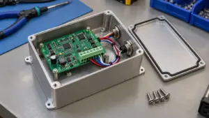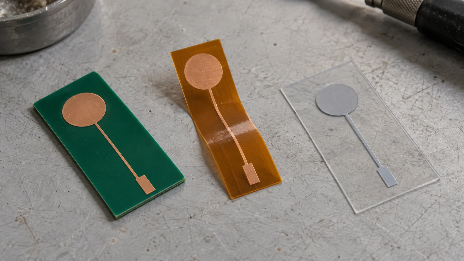
Shortlist rigid PCB for a flat sensor with board-mounted electronics, copper FPC when copper routing must follow a defined bend, and printed PET for a thin sensor circuit bonded behind the front surface. Treat these as starting architectures, not interchangeable materials or a universal cost ranking. Manufacturer construction examples show both integrated boards and flexible sensors connected to separate electronics. See Boyd’s capacitive-touch construction guide.
A capacitive touch PCB vs FPC comparison should therefore include printed film as a distinct third route. Select the complete construction around the enclosure, light path, controller and assembly process—not flexibility alone.
This article focuses on fixed-function touch controls. For broader cover, interface and system planning, use the custom capacitive touch panel design guide.
- Distinguish Copper Flex from Printed Film Circuits
- Compare Shape, Routing and Controller Location
- Separate installation bending from repeated movement
- Decide where raw sensing ends
- Review Lighting and Transparent-Area Needs
- Define Interconnect and Assembly Requirements
- Validate the Chosen Production Construction
- Review Your Sensor Construction
Distinguish Copper Flex from Printed Film Circuits
Specify the conductor and substrate together; “flex circuit” alone is ambiguous. In this comparison, rigid PCB means copper circuitry on a rigid board, commonly FR-4. Copper FPC means patterned copper on a flexible dielectric, commonly polyimide. Pyralux AP copper-clad polyimide is one material-family example, not a prescribed project material.
Printed film means a conductive-ink circuit on a specified film, here PET. Its ink and insulating layers need their own process specification. Henkel’s printed-electronics materials overview distinguishes conductive and dielectric inks; it does not make every ink suitable for every substrate or assembly process. Do not confuse the PET sensor circuit with a separate decorative PET overlay.
Use the table as a construction-review framework, not a capability guarantee. Minco’s flex-circuit design guide provides background on copper-flex layers, component mounting and reinforced terminations.
| Decision dimension | Rigid copper PCB | Copper FPC | Printed PET circuit |
|---|---|---|---|
| Conductor and substrate | Copper on a specified rigid laminate | Copper on specified flexible dielectric, often polyimide | Specified conductive ink on PET; define insulating/protective layers |
| Shape | Rigid carrier; define flatness and support | Flexible regions with locally reinforced areas as needed | Conformable film; qualify the bonded contour and forming |
| Routing | Copper layers and vias according to the board stack | Copper layers/vias with coverlay and bend-zone restrictions | Printed traces and insulated crossovers; qualify printing registration |
| Lighting | Plan the light path around board and copper | Identify conductor-free areas or openings | Specify whether each light area is unprinted or uses a qualified transparent construction |
| Components and controller | Review available board area and assembly access | Define supported component areas or a separate board | Specify separate electronics or a specifically qualified attachment process |
| Connection | Define connector, pads or cable assembly | Define integral tail, contacts and local stiffening | Define printed tail, contact system and reinforcement |
| Assembly evidence | Board position and sensor-to-cover spacing | Bonding, strain relief and reinforced transitions | Lamination, registration and process compatibility |
| Production checks | Fabricated geometry and installed response | Electrical checks before and after forming | Printed-circuit resistance, insulation and post-lamination response |
For every quotation, request the proposed layer stack, conductor system and manufacturing drawings. Ask suppliers to identify which routing features and assembly operations they have actually qualified; do not assume that a copper design can be transferred unchanged to printing.
For related contact-switch structures, see PCB and FPC membrane switches—related circuit constructions. That is a membrane-switch product page, not a dedicated capacitive-sensor specification.
Compare Shape, Routing and Controller Location
Choose the installed geometry and controller position together. A mechanically convenient tail is not automatically an electrically acceptable sensor connection.
Separate installation bending from repeated movement
Specify whether the circuit is formed during assembly, moved during servicing or repeatedly flexed in operation. Copper-flex construction, material placement and bend geometry affect reliability; flexible constituent materials do not guarantee a durable finished circuit. Minco’s flexibility guide explains this distinction.
Require a flat drawing and an installed view showing bend zones, proposed radii, attachment points and reinforced transitions. For printed PET, obtain the ink-and-film supplier’s forming limits rather than borrowing copper-flex rules. Do not assume that bending around a simple curve also permits stretching over a compound surface.
Record the approved stack and movement requirement together. Replacing the conductor, reinforcement or adhesive should trigger a review of that approval.
Decide where raw sensing ends
A flexible sensor can connect to a nearby touch-controller board or to a controller on the main PCB. Boyd illustrates both arrangements. The useful comparison is the electrode-to-controller connection, followed separately by the controller-to-host interface.
The Texas Instruments CapTIvate design guide explains how conductor resistance and parasitic capacitance influence sensing. A longer raw-sensor connection changes the circuit being measured; a digital connection after the controller is a different interface with its own electrical limits.
For each candidate, record raw-trace routing, controller-compatible capacitance limits, connector transitions and nearby switching circuits. Check grounding against the selected controller’s guidance.
For the printed option, request cured-ink sheet resistance, deposited thickness and coupon results; do not calculate from a bulk-silver property table. For copper options, record foil thickness and finished geometry. Include measured electrode-to-connector resistance in the comparison.
Compare a remote-controller arrangement with a local-controller arrangement when packaging permits. Retain each candidate’s layout and configuration with its results; “same controller” does not establish an equivalent test setup.
Review Lighting and Transparent-Area Needs
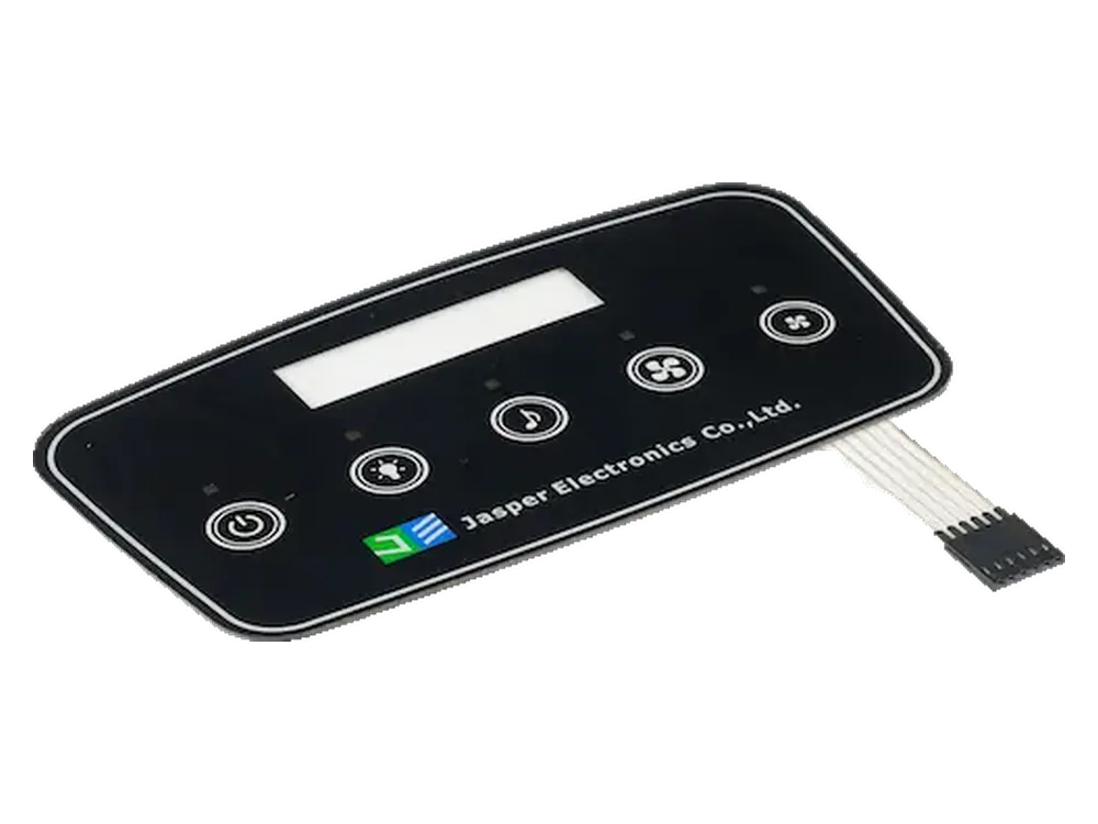
Separate a light opening from a transparent sensing area. A clear PET base does not establish that the finished conductor, dielectric, adhesive and graphics transmit the required light. Boyd’s backlit examples explicitly use transparent or translucent circuit constructions; they do not establish transparency for every printed film.
On the combined artwork, identify the touch target, electrode boundary, lit symbol, display viewing area and opaque mask. For each area, decide whether light must pass through a conductor, through an unprinted region or through a physical opening.
A PCB opening for a rear-mounted LED is one possible arrangement. TI cautions that changing the opening can affect touch coverage, while LED circuitry can interfere with sensing. Do not approve the optical layout from appearance alone.
Compare candidates using the intended cover, graphics, adhesive, diffuser and light source. Check lit and unlit appearance, symbol alignment, light leakage and sensing across the target with the relevant lighting modes active. Record the viewing conditions, lighting drive state, stack revision and corresponding touch results.
A transparent coordinate-touch area over a display requires a separate sensor/controller specification. Do not assume that routing discrete buttons around a clear window provides coordinate sensing within that window.
Define Interconnect and Assembly Requirements
Approve the termination, mounting process and purchased output—not merely the tail pitch. Copper flex may use reinforced termination or component areas, as described by Minco; specify where those reinforcements end relative to the intended bend.
For either flexible construction, obtain the mating connector’s requirements for contact material, finished thickness, orientation, reinforcement and insertion duty. For printed PET, explicitly qualify the joining method and heat exposure instead of carrying over a rigid-board soldering specification. Include process samples in that approval.
Plan assembly access before releasing the tail. Show how the operator grips and inserts it, how the latch is reached and where strain relief acts. Request confirmation that the installed route avoids pulling the sensor away from the cover.
Use the following supply-boundary table in the RFQ. Name the actual responsible company or team for each row; the carrier name does not assign ownership.
| Boundary | State the purchased output | Name the acceptance owner and evidence |
|---|---|---|
| Cover and bonding stack | Cover, graphics, adhesive and included lamination operations | Mechanical/optical owner; approved stack and registration drawing |
| Sensor and termination | Electrode carrier, protective layers, tail, contacts and included connector | Sensor/interface owner; fabrication revision, pinout and electrical inspection record |
| Controller hardware | Bare-sensor connection or included controller board; power and host interface | Electronics owner; schematic, device identity and interface specification |
| Firmware and tuning | Included configuration, source/binary deliverables and revision control | Firmware owner; configuration record, diagnostics and accepted key-event behavior |
| Display and lighting | Included, separately supplied or excluded display, LEDs, drivers and optics | Display/lighting owner; mechanical interfaces and operating modes for testing |
| Host and final equipment | Command mapping, startup, fault handling and final integration | OEM/system owner; installed acceptance plan and host-event log |
Also state whether inspection ends at circuit continuity, assembled sensor diagnostics or accepted host commands. Those are different purchased outputs.
TI’s dielectric-stack guidance explains why sensor-to-cover spacing and unintended air gaps deserve control. In the proposed assembly trial, compare baseline measurements before and after bonding, recording the bonding method and support arrangement.
Validate the Chosen Production Construction
Approve production-intent constructions against the same equipment requirements, not against the same-looking artwork. Use the following proposed comparison method to keep material selection separate from unsupported performance claims.
First establish common cover, enclosure, input conditions, light modes and accepted host behavior. Then allow each carrier an appropriate manufacturable layout, recording any controller or configuration differences. This avoids penalizing one process with artwork designed solely for another.
Illustrative validation record; actual results are intentionally blank.
| Check | Conditions and evidence to record | Actual result |
|---|---|---|
| Construction identity | Material/ink/laminate, layer stack, drawing revision, lot and controller configuration | |
| Electrical integrity | Continuity, isolation and relevant trace/contact resistance before and after assembly | |
| Installed key operation | Intended press/release events, adjacent-key rejection and corresponding host commands | |
| Lighting interaction | Required display/LED modes, optical observations and touch logs | |
| Forming and service movement | Approved bend path, movement duty, inspection and post-movement function | |
| Application exposure | Specified operating, storage and cleaning conditions; before/after electrical and functional evidence |
Define project-specific acceptance limits and the sampling plan before testing. For fixed-function keys, log press, release and host events; do not substitute a PCAP coordinate or multitouch report. Likewise, do not use enclosure ingress evidence as proof of wet-touch behavior, or ordinary key validation as approval for a safety function.
Release the approved material stack, artwork, termination, assembly instructions and controller configuration as one controlled package. Identify which changes require targeted revalidation, including an ink substitution, new laminate, altered stiffener, different adhesive or revised tail route.
Frequently Asked Questions
Use these questions to resolve drawing transfers, quotation differences and approval gaps before ordering samples.
Can existing PCB electrode artwork be reused for printed PET?
Use it as a functional reference, not a production-ready transfer. Request a new manufacturing review of conductor geometry, crossovers, resistance, dielectric layers and connector pads. Approve the resulting film construction with its intended controller and cover.
Can copper FPC and printed PET use the same connector?
Possibly, but matching pitch is insufficient. Obtain approval for the finished tail thickness, contact material, contact orientation, stiffener and insertion requirements. Identify the exact mating connector in both drawings before approving interchangeability.
Does a backlit touch symbol require a transparent electrode?
Not necessarily. Evaluate a light opening within or beside the electrode, or a separately qualified transparent construction. Check both illuminated appearance and touch coverage; a bright symbol alone does not demonstrate acceptable sensing.
Can a rigid-board prototype approve a printed-film production design?
Treat that prototype as concept evidence only. Require production-intent film, ink, protection, adhesive and termination before approving the printed-film route. Keep the controller configuration and assembly revision with the approval record.
Which construction has the lowest total cost?
Compare quotations at the same quantities and purchased scope. Include the sensor, controller board, connectors, stiffeners, bonding, assembly, electrical testing, tooling and replacement strategy. Do not select a carrier from its bare-circuit price alone.
What should a serviceable panel specify about bending?
State whether bending occurs only during installation, during maintenance or throughout normal operation. Define the installed path, proposed radius, movement, expected cycles and environment, then obtain construction-specific acceptance criteria. Do not substitute a general flexible-material description for this requirement.
What evidence should a second-source supplier provide?
Request its proposed material and process stack, interface drawing, representative samples and results against the same installed acceptance plan. Track any differences in controller configuration. A matching outline and pinout are not sufficient approval evidence.
Review Your Sensor Construction
Submit the installed configuration and requested supply boundary, not only the visible icon artwork. For a project involving custom capacitive touch panels, provide enclosure CAD, cover/adhesive stack, electrode layout, light and clear-area requirements, controller location, tail route, connector details and operating conditions. Include installation or service-bend requirements, prototype quantity, production quantities and expected annual demand.
Specify whether the requested quotation covers a bare sensor, sensor with controller, or assembled front, and identify customer-supplied parts.
Ready to Start Your Project?
Tell us about your membrane switch, keypad, or graphic overlay requirements. Our engineering team will review your specifications and provide a detailed quote.