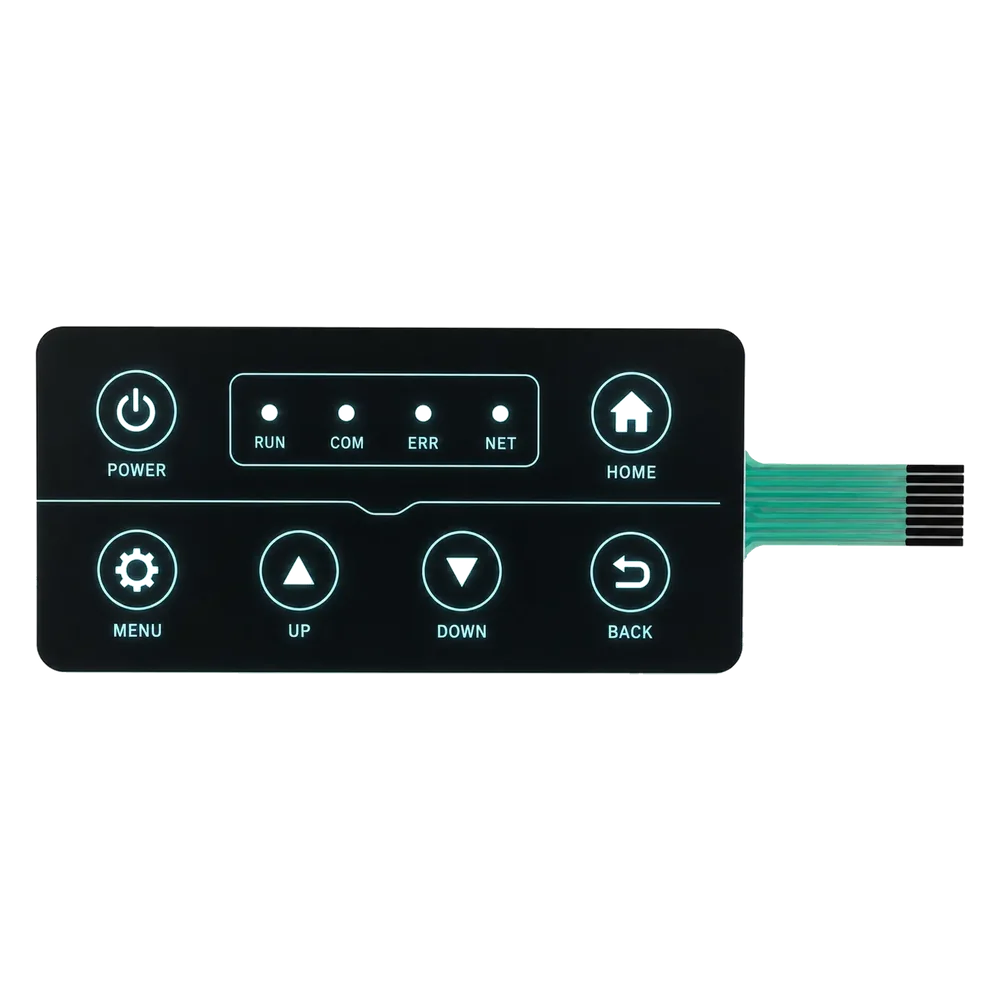
Backlit membrane keypads fail in the field for two distinct optical reasons, and OEM design teams routinely conflate them. Hotspots are zones of excess brightness where an LED is too close to the overlay; light leakage is the unwanted escape of luminance through regions that the graphic overlay was meant to keep dark. Leakage shows up as halos around character windows, glow along key borders, and bleed-through on the device fascia at night. ISO 9241-303:2011 sets the visual-display ergonomics baseline that most industrial OEMs use to judge whether a backlit keypad has passed optical QA, and peripheral leakage above roughly 5% of peak luminance at 1/3 of the LED pitch is the typical reject threshold for medical and avionics work.
Backlit keypad light-leakage review starts with five root causes, the four-layer optical-defense stack that engineers in 2026 use to prevent it, the comparison between the four common backlight architectures, and a quantified pass-fail test method based on luminance-meter readings.
- What is light leakage — and how it differs from hotspots
- The 5 root causes of light leakage
- The four-layer defense stack
- (a) Blocking ink stack-up
- (b) Selective diffuser layer
- (c) LGF edge confinement
- (d) Window-to-keytop alignment tolerance
- Comparison: four backlight architectures × leakage profile
- Quantified test method
- Seven-point design checklist for leakage-free backlit keypads
What is light leakage — and how it differs from hotspots
Light leakage is the visible escape of LED or LGF (light-guide film) luminance through nominally opaque regions of a graphic overlay. The three failure modes that field-return reports cite most often are: character-window halo (a faint glow extending 1–3 mm beyond the legend), key-edge glow (a bright outline that traces the embossed key boundary), and panel-edge bleed (light escaping along the bezel where the overlay terminates). All three are leakage. None of them are hotspots.
Hotspots are local brightness peaks caused by uneven LED-to-overlay distance or insufficient diffusion; they appear inside the lit region rather than outside it. A keypad can be hotspot-free and still leak badly. Conversely, an overlay can show no leakage while exhibiting severe hotspots. The two defects are mitigated by different layers in the optical stack, which is why blending them into a single problem produces blended, half-effective fixes. The bx-panel.com OEM guide that ranks well for “even backlighting” focuses primarily on hotspot suppression; the technical reference addresses the parallel and largely orthogonal problem of leakage.
The 5 root causes of light leakage
Five mechanisms account for the vast majority of leakage complaints that reach Tier-1 OEM optical engineers in North America and Western Europe.
- Insufficient blocking-ink coats on the rear of the overlay. A single pass of opaque black ink (Marabu MGL series at ~6 µm dry film) blocks roughly 95–97% of incident luminance at 470 nm; two passes push that to ≥99.5%. One-coat overlays leak.
- Ink mis-registration at the character window. When the printed character window edge drifts more than ±0.05 mm relative to the embossed key, the blocking layer no longer fully overlaps the diffuser cutout, producing a thin crescent of bleed.
- Diffuser-film overhang or underhang. A PC or PET diffuser film cut larger than its window will spread light past the blocking ink; cut smaller, it creates a dark band that engineers sometimes “fix” by reducing blocking-ink opacity — a classic anti-pattern.
- LGF reflector gaps at the panel edge. LGFs (light-guide films, typically 0.2–0.5 mm PC or PMMA) emit downward as well as upward; if the white reflector backing is not flush to the LGF edge, lateral light escapes along the bezel. IEC 60068-2-78 damp-heat conditioning frequently surfaces this defect because the reflector adhesive softens and recedes.
- Adhesive squeeze-out into the optical zone. Pressure-sensitive adhesives (typically 50–125 µm acrylic transfer tapes from 3M or Tesa) can flow into the optical window during lamination, creating localized refractive-index mismatches that scatter light outward.
The four-layer defense stack
The four layers below are listed in the order they appear in a typical overlay cross-section, from the user-facing top surface downward toward the PCB. IPC-2221 covers the PCB-side aspects; the rest is overlay-process engineering.
(a) Blocking ink stack-up
The blocking layer is the single most important defense against leakage. It sits directly under the diffuser layer of the overlay, printed onto the second surface of the PC or PET substrate. Two coats of opaque black ink — typically a screen-printed solvent-based polyester ink such as Marabu MGL 069, Coates Screen Inks ICR series, or Nazdar 5500 series — deliver an optical density (OD) of 4.0–4.5, equivalent to ≤0.01% luminance transmission. UL 969 governs label durability for the overlay material and indirectly constrains which inks can be used in regulated devices.
| Ink stack-up option | Typical OD | Coats | Dry-film thickness | Known suppliers |
|---|---|---|---|---|
| Single-coat opaque black | 2.5–3.0 | 1 | 6–8 µm | Marabu MGL, Coates ICR |
| Two-coat opaque black | 4.0–4.5 | 2 | 12–16 µm | Marabu MGL, Nazdar 5500 |
| Black + white sandwich | 4.5+ | 3 | 18–22 µm | Marabu MGL + MGW |
| Black + halftone window | 3.5–4.0 | 2 + halftone | 14 µm + 6 µm | Sun Chemical Streetjet, Coates ICR |
The black-plus-white sandwich is the leakage-blocking gold standard: a white ink layer above the black returns stray light back into the diffuser before it can escape laterally. This three-coat stack costs about 18–25% more per unit than two-coat black and is standard for medical infusion-pump fascias and aerospace cockpit overlays.
(b) Selective diffuser layer
A diffuser film placed above the LGF or LED array randomizes ray angles, which reduces hotspot intensity and indirectly reduces leakage by lowering peak luminance at any single point. Common diffuser substrates are 100–250 µm PC or PET films with embedded TiO₂ or SiO₂ particles; the 3M Vikuiti DBEF-Q series adds a brightness-enhancing prism layer that lowers the LED count needed for a given lux target.
A diffuser does not by itself stop leakage — it changes the angular distribution of light that then encounters the blocking ink. Pairing a high-haze diffuser (>90% haze) with a two-coat blocking ink reduces measured edge leakage by 40–60% versus a low-haze diffuser at the same blocking-ink stack-up.
(c) LGF edge confinement
Edge-lit designs using a Saint-Gobain or 3M LGF substrate require a continuous white reflector film bonded to the underside, with the reflector edge extending at least 0.3 mm beyond the LGF edge. A polyester guard ring — a 0.1–0.3 mm wide opaque polyester strip wrapped around the LGF perimeter — is the standard secondary defense for medical and outdoor devices subject to IEC 60068-2-78 thermal cycling. Without the guard ring, lateral light escape at the LGF perimeter accounts for 30–50% of total leakage in field returns.
(d) Window-to-keytop alignment tolerance
The final layer is geometric rather than material. The printed character window, the embossed key, and the LED or LGF emission zone must align within ±0.05 mm in X-Y. Looser tolerances (the legacy ±0.15 mm standard from late-1990s overlay specifications) are now associated with 3–5× higher leakage reject rates on small character heights (≤3 mm). Tier-1 medical-device OEMs typically require ±0.05 mm and verify with optical-coordinate measurement before assembly.
Comparison: four backlight architectures × leakage profile
| Architecture | Typical leakage failure mode | Primary mitigation layer | Cost vs. LGF baseline | Common application |
|---|---|---|---|---|
| LGF (light-guide film) | LGF-edge lateral bleed | Reflector + guard ring | 1.0× | Medical, industrial control |
| Top-lit LED through dome | Halo around dome boundary | Two-coat blocking ink + diffuser | 0.6–0.8× | Consumer appliances, low-end industrial |
| Edge-lit EL (electroluminescent) | Uniform low-level glow leakage | Three-coat black + white sandwich | 1.3–1.6× | Avionics, military |
| Side-fired RGB LED arrays | Color-fringed perimeter glow | LGF + chromatic diffuser | 1.8–2.4× | Premium automotive HMI |
LGF is the OEM workhorse for industrial and medical work; top-lit LED dominates cost-sensitive consumer applications; EL persists in avionics where uniformity outweighs cost; side-fired RGB is the premium-segment choice. Vendor-neutral specialists such as bx-panel.com and csikeyboards.com supply LGF and top-lit LED configurations; Jasper Electronics‘ production stack-up for industrial and medical OEMs uses the two-coat blocking ink + LGF + polyester guard-ring combination shown in row 1 of the table above.
Quantified test method
Pass-fail criteria for leakage are best measured with a calibrated luminance meter such as the Konica Minolta LS-160 or the Topcon BM-7A, positioned normal to the overlay at a working distance of 350 mm under a dark-room condition (ambient ≤0.1 lx). IEC 60598-1 sets the broader photometric conventions; the three thresholds below are the working numbers that medical and industrial OEMs commonly write into their acceptance specifications.
| Metric | Pass threshold | Measurement point |
|---|---|---|
| Luminance uniformity across the lit window | ≥80% | 9-point grid, edge points at 10% inset |
| ON/OFF contrast ratio | ≥10:1 | Lit vs. adjacent unlit region |
| Peripheral leakage | ≤5% of peak luminance | At 1/3 LED-to-LED pitch outside the window |
A keypad that meets all three thresholds will read as “clean” to the naked eye in a darkened cabin or operating room — the practical benchmark that field engineers actually apply.
Seven-point design checklist for leakage-free backlit keypads
- Specify two-coat opaque black blocking ink minimum (Marabu MGL or Coates ICR equivalent).
- For medical or avionics: upgrade to the three-coat black + white sandwich for ≥4.5 OD.
- Set window-to-keytop registration tolerance at ±0.05 mm; verify with optical-coordinate measurement.
- Match diffuser haze (≥90%) to blocking-ink opacity; never reduce ink to “fix” diffuser-cut darkness.
- For LGF architectures: extend the white reflector ≥0.3 mm past the LGF edge and add a polyester guard ring.
- Validate the assembly after 96 hours of IEC 60068-2-78 damp-heat conditioning, not only at room ambient.
- Acceptance test with a luminance meter against the 80% / 10:1 / 5% thresholds above; do not rely on visual inspection alone.
Frequently Asked Questions
How do I prevent light leakage on a backlit membrane keypad?
Prevent leakage by attacking the four-layer optical stack in order: specify a two-coat opaque black blocking ink (Marabu MGL, Coates ICR, or Nazdar 5500) on the rear of the overlay, add a high-haze (>90%) PC or PET diffuser above the LGF or LED array, extend the white reflector film 0.3 mm past the LGF edge with a polyester guard ring for edge confinement, and lock window-to-keytop registration at ±0.05 mm. Validate after IEC 60068-2-78 damp-heat conditioning with a luminance meter such as the Konica Minolta LS-160, targeting ≥80% uniformity, ≥10:1 contrast, and ≤5% peripheral leakage. Skipping any single layer multiplies field-return rates.
What blocking ink layer stops LED bleed in a graphic overlay?
The industry-standard blocking layer is two coats of opaque black screen-printed solvent ink — typically Marabu MGL 069, Coates Screen Inks ICR series, or Nazdar 5500 series — printed on the second surface of a polycarbonate or polyester overlay substrate. Two coats yield an optical density of 4.0–4.5, equivalent to ≤0.01% luminance transmission at 470 nm LED output. For medical infusion pumps, avionics cockpit overlays, and other applications where dark-cabin contrast is critical, designers upgrade to a three-coat sandwich (black + white + black) for OD ≥4.5. UL 969 governs the durability rating of the overlay material that carries the ink.
Why is my backlit keypad glowing around the key edges?
Edge glow on a backlit membrane keypad usually points to one of three root causes: under-coated blocking ink (a single-pass opaque black instead of two coats), ink-to-keytop mis-registration greater than ±0.05 mm, or a recessed LGF reflector film that has pulled back from the LGF edge after thermal cycling. The diagnostic order is to measure perimeter luminance with a Konica Minolta LS-160 or equivalent — if it exceeds 5% of peak luminance at 1/3 the LED pitch, the overlay is failing. Inspect the reflector edge first, then the ink registration, then the blocking-coat count.
Jasper Electronics prepared the technical reference as an OEM membrane-switch and backlit keypad manufacturer building custom assemblies for industrial, medical, and automotive customers worldwide since 2002.
Ready to Start Your Project?
Tell us about your membrane switch, keypad, or graphic overlay requirements. Our engineering team will review your specifications and provide a detailed quote.