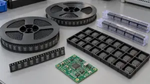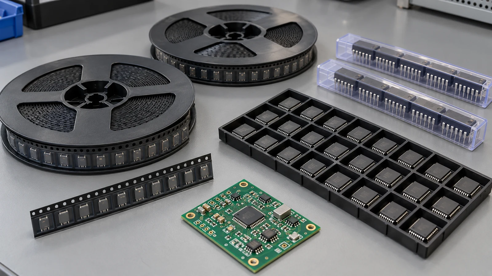
PCB assembly component packaging is the carrier and protective system that presents identified, correctly oriented parts to an assembly process. Prepare each format for its actual feed method: tape feeders for reels, an accepted short-tape method for cut tape, tray handling for matrix carriers, and matched tracks for tubes. For repeat SMT production, use factory 330 mm reels as the planning benchmark when the ordering option and reel holder support them. Preserve the manufacturer’s orientation, moisture and ESD controls, and agree leader, trailer and quantity requirements with the assembler before shipping.
- Reels, Cut Tape, Trays and Tubes Need Different Feed Methods
- Identify Parts and Orientation Without Opening the Wrong Package
- Check Leaders, Trailers and Feeder Compatibility
- Read the interface dimensions separately
- Agree the loading ends before preparing cut tape
- Protect Tray and Tube Parts During Handling and Transfer
- Match the tray beyond its outside dimensions
- Match tube profile and discharge direction
- Preserve Moisture and ESD Controls During Repacking
- Confirm Packaging Acceptance Before Shipping the Kit
- Apply the Packaging Checks to Five Assembly Situations
- Prototype build supplied as several cut-tape strips
- Repeat SMT production with a factory reel option
- Small capacitors changed to narrow-pitch tape
- BGA parts transferred after laboratory evaluation
- Tube-fed connectors or molded packages
- Prepare the Packaging Handoff for JASPER
Reels, Cut Tape, Trays and Tubes Need Different Feed Methods
Reels and cut tape present components in sequential pockets; trays present a coordinate matrix; tubes guide components along a shaped channel. The assembly line must have the corresponding feeder, holder and pickup setup. A correct component in an incompatible carrier can still interrupt production.
Tape feeding engages the carrier’s feed holes, advances the pockets and presents a component at the pickup point. The reel stores tape; it does not define the feeder setting. Trays require pocket coordinates and a known orientation. Tube feeding requires a compatible track and a controlled way to move the next component into position.
Use the same questions for all four formats:
| Packaging Format | Feeding Requirement | Orientation Check | Protection Requirement | Supplier Confirmation |
|---|---|---|---|---|
| Full reel | Match tape geometry, reel holder and cover-tape handling to the feeder | Compare pin 1 or polarity with the feed direction and packing drawing | Keep pockets covered; protect reel flanges and retain required dry pack | Exact orderable part number, reel diameter, tape specification and accepted reel condition |
| Cut tape | Use an accepted short-tape fixture, feeder or controlled re-reeling method | Retain original pocket orientation and identify the loading end | Support strips against bending; retain cover tape and required moisture/ESD protection | Accepted strip condition, leader/trailer arrangement and handling of separated strips |
| Tray | Match outline, pocket matrix, pitch, height and holder | Check the tray datum, pin 1 and component face | Protect leads or balls; secure the stack with a compatible cover | Tray drawing, populated-pocket map, orientation and thermal rating |
| Tube | Match cross-section, exit geometry and feeder track | Identify the discharge end, pin 1 and component face | Retain suitable end stops; prevent escape, jamming and lead damage | Tube profile, dimensions, feeding direction and compatible fixture |
For a repeat order, preserve the accepted carrier specification alongside the component ordering information. An electrically identical part can arrive in a different carrier because its packaging suffix or packing arrangement changed. Treat that change as a feed-setup review.
The physical handoff is simple:
Identify the sealed carrier → match its drawing to the feed method → agree preparation → preserve protection → release the package for shipment.
Resolve the interface before a packing team cuts tape or transfers parts. Repacking should solve a defined compatibility problem, with the receiving line involved in the decision.
Identify Parts and Orientation Without Opening the Wrong Package
Identify components from the outside label and packing documents before opening their protective package. Match the complete manufacturer part number, including its packing suffix, to the approved BOM line. A stockroom nickname or a package-body marking alone does not identify the supplied ordering option.
Keep the manufacturer’s label readable. If a reel is divided, each resulting package needs its own identity linked to the original label: manufacturer, full part number, contained quantity, lot/date information, carrier identifier and applicable moisture-handling information. Label every separated package. A label image is useful evidence, but it cannot identify a loose strip after that strip becomes separated from its accompanying email.
Use the carrier drawing and its stated viewing direction to define orientation. Record pin 1 or polarity relative to the tape’s sprocket edge and feed direction, tray datum or tube discharge end. In the Q2 tape example, retain the drawing defining Q2 against the sprocket holes and feed arrow. Q2 alone is insufficient, and top and bottom views differ.
Keep the three data roles separate. The BOM identifies the part and its board reference designators. The CPL supplies placement coordinates, rotation and board side. The packing drawing explains how the component sits in its carrier. The referenced supplier’s BOM and CPL guidance defines the first two responsibilities. A carrier’s pin-1 quadrant is not a replacement for the CPL rotation.
Provide exterior label photographs and the relevant packing drawing while the moisture barrier bag remains sealed. When a label conflict requires opening, arrange a controlled inspection and retain the exposure record with the parts. Do not peel back cover tape merely to make an identification photograph easier.
Separate different part numbers and distinct source identities into clearly identified carriers. This section’s objective is to preserve identity through preparation; the full kit’s shortage reconciliation and finished-board traceability belong to their own records.
Check Leaders, Trailers and Feeder Compatibility
A usable tape package must match the feeder’s tape width, indexing geometry, pocket clearance and cover-tape mechanism. Leader and trailer requirements come from that exact loading method. Confirm them with a feeder drawing or an accepted setup instruction before cutting, splicing or re-reeling components.
Read the interface dimensions separately
Tape width W, feed-hole pitch P0 and pocket pitch P1 describe different features. Reel diameter adds another interface. The following checks prevent a nominally correct tape width from hiding an incompatible feed arrangement.
| Interface | Published options or example | Assembly decision |
|---|---|---|
| Tape width W | Agilis/Agilis Flex combined configuration options: 4 mm, 8 mm, 12 mm, 16 mm, 24 mm, 32 mm, 44 mm, 56 mm, 72 mm, 88 mm, 104 mm, 120 mm, 136 mm, 152 mm | Select the actual feeder variant and accessories; these widths are not one feeder’s adjustment range |
| Reel diameter | Agilis lists 180 mm and 330 mm ordinary reel options | Check holder diameter, hub, flange clearance and tape exit path |
| Feed-hole pitch P0 | Packaging example: 4 mm for original paper tape; 2 mm for narrow embossed tape | Confirm sprocket/indexing compatibility |
| Pocket pitch P1 | Packaging example: 2 mm for original paper tape; 1 mm for narrow embossed tape | Set the pocket advance independently of feed-hole pitch |
| Pocket geometry | A0 accommodates component width; B0 length; K0 thickness | Check the component and loaded-pocket clearance, not just W |
| Cover-tape interface | Carrier material, cover construction and opening method | Confirm that the feeder can expose the part without lifting it or damaging the carrier |
The listed width and reel options describe specific feeder configurations. They are not a universal machine-capability list; confirm the installed configuration before accepting a carrier.
The 01005 (0402M) packaging example has two distinct formats: original paper tape with W/P0/P1 of 8/4/2 mm and narrow-pitch embossed tape with 4/2/1 mm. The smaller format needs its corresponding feeding setup. Use the complete specified geometry instead of assuming that every feed-hole pitch is 4 mm.
The documented CC2640F128RGZR configuration uses a 330 mm reel, while CC2640F128RGZT uses a 180 mm reel. Both RGZ options have 16 mm tape, 12 mm pocket pitch, Q2 pin-1 orientation and 7.3 mm by 7.3 mm by 1.1 mm pockets. A 330 mm planning benchmark does not change this CC2640 tape geometry. Retain the available smaller reel when it better fits demand.
Agree the loading ends before preparing cut tape
Ask the assembler to distinguish empty carrier length before the first occupied pocket, the free cover-tape end, and support after the last usable pocket. Also identify where an approved splice may sit. A single instruction to “add a leader” leaves these details unresolved.
Short strips may need a dedicated fixture or a prepared tape path. Tape Clip Magazine is one such short-strip accessory; its availability does not establish that another line accepts the same carrier or setup.
Keep strips flat and supported, with pockets covered. Send their lengths, physical condition and photographs for review. Agree any setup consumption and usable quantity for the actual job; neither a fixed number of spare parts nor a universal leader length can establish compatibility.
Protect Tray and Tube Parts During Handling and Transfer
Tray and tube parts need carriers that support the package without loading its vulnerable leads, balls or surfaces. Keep the original carrier when it fits the receiving equipment. Transfer parts only into a compatible, identified carrier using a controlled handling method.
Match the tray beyond its outside dimensions
A tray holder’s fit does not establish pocket compatibility. Check the pocket shape, support features, pitch, depth, component face and stack clearance. Retain the tray drawing or molded identification so the receiving team can distinguish similar-looking designs.
Tray drawing 50-8068 distinguishes a 315.0 mm body length from a 322.6 mm overall dimension and specifies a 135.9 mm width. Use the complete envelope: comparing only body length can miss projections that affect holder clearance.
For a partially populated tray, supply a pocket map and secure the stack with a matching cover. Do not fill empty pockets with loose paper or foam. When a transfer is necessary, confirm that the receiving pocket supports the intended surfaces, prevents rotation and leaves the pickup surface accessible. Preserve orientation and source identity throughout the move.
Match tube profile and discharge direction
SOIC, DPAK, PLCC and connector tubes may require different positioners. Check the internal channel and external envelope. The specified ASP10 pallet accepts 10.5 mm stick height; ASP1028 lists 10.5 mm at positions 1–8 and 28.5 mm at positions 9–16. A feeder name alone does not define these limits.
Keep suitable end stops fitted during transport. Mark the intended discharge end without obstructing the channel, and confirm the device face and pin-1 direction at the exit. A jammed component needs inspection of the tube, lead condition and track alignment. Forcing it through can damage the part and leave the original feed problem unresolved.
Preserve Moisture and ESD Controls During Repacking
Repacking must preserve the component’s moisture condition and ESD protection as well as its mechanical orientation. Moving a device into a different carrier does not change its MSL classification. Opening the dry pack can, however, add exposure time and change what must happen before reflow.
Use the device label and handling instruction to control exposure. Record when the moisture barrier bag was opened, the relevant environment, intervening storage and any approved drying operation. Keep that history with each separated package. Simply resealing a bag does not reset an exhausted floor life or establish that an unknown exposure history is acceptable.
Hold parts for a defined disposition if history is incomplete or permitted exposure has been exceeded. Select drying conditions from the applicable device instructions and handling procedure, and check the carrier’s thermal limit. Some FLASH shipping tape/reel carriers cannot tolerate higher-temperature baking; assess the actual carrier rather than specifying one bake temperature for every kit.
Restore the required dry-pack system with suitable moisture barrier packaging, desiccant, humidity indication and identification. Avoid opening sealed packages merely to count parts visually. Properly stored products generally do not need baking before production; determine any exception from the device requirements and exposure record.
Keep these document responsibilities distinct:
| Document or standard | Packaging role | Buyer action |
|---|---|---|
| ANSI/EIA 481-F-2021, identified in the ECIA published list | Carrier-taping interface framework | Require the applicable packing drawing and contract-specified edition |
| IPC/JEDEC J-STD-020 | Moisture/reflow sensitivity classification | Retain the device’s assigned MSL and reflow classification |
| IPC/JEDEC J-STD-033D | Handling, packing and use of moisture/reflow/process-sensitive devices | Carry exposure and dry-pack information through transfers |
| ANSI/ESD S541-2026 | Protective packaging for ESD-sensitive items | Specify protective properties suitable for handling, transport and storage |
The IPC J-STD-033D scope addresses moisture-related handling; it does not replace the feeder drawing.
Perform exposed handling in the site’s ESD protected area. For transport outside that area, select the required discharge-shielding system; “antistatic” material or bag color alone does not establish it. The EOS/ESD Association’s packaging guidance distinguishes in-area handling properties from the additional protection needed outside the controlled area. Moisture protection and ESD shielding must both survive repacking.
Confirm Packaging Acceptance Before Shipping the Kit
Packaging acceptance should identify the supplied carrier, the receiving feed method and any preparation needed before loading. Obtain that agreement while the parts are still under the sender’s control. A packing list that says only “ICs supplied” does not answer the line’s interface questions.
Send a compact packaging record for each distinct carrier arrangement. The entries below describe completed information to provide, rather than an instruction to alter the manufacturer’s packaging.
| Record item | Information to send | Receiving-team decision |
|---|---|---|
| Identity | Complete manufacturer part number, BOM reference and readable original label | Match the supplied ordering option to the intended part |
| Reel or tape interface | Diameter, W/P0/P1, carrier drawing and photographs of accessible tape ends | Confirm feeder, holder, opening method and preparation instruction |
| Tray or tube interface | Carrier identification, outline/profile drawing, orientation and partial-fill information | Confirm holder or track, pickup datum and transfer requirements |
| Protective condition | Seal condition, MSL information, exposure record when opened and ESD packaging description | Accept the protection or specify a handling disposition |
| Preparation responsibility | Proposed cutting, splicing, re-reeling or carrier transfer and who performs it | Approve the method and retain identity after the operation |
| Release record | The agreed carrier arrangement and the person confirming it | Record acceptance as supplied, acceptance after defined preparation, or a hold |
For CC2640F128RGZT, the documented carrier record is: 180 mm reel; 16 mm tape; 12 mm pocket pitch; 7.3 mm by 7.3 mm by 1.1 mm pocket; Q2 orientation defined by the feed-direction drawing. Add the actual label and protective-condition record so receiving can match the carrier to its setup and return a specific packaging acceptance decision.
Treat an unexpected carrier substitution as a change to the accepted record. If the approved tray is replaced, or several strips arrive where a reel was expected, reopen the affected packaging decision before loading. Keep any production quantity or setup-consumption agreement specific to that job.
Apply the Packaging Checks to Five Assembly Situations
The appropriate preparation route follows the supplied carrier and the receiving equipment. These five situations show how to turn the dimensional and handling checks into a decision before shipment. They are assembly-planning examples, not fixed acceptance rules for every production line.
Prototype build supplied as several cut-tape strips
Keep the original pockets covered. Before requesting a preparation method, send photographs showing each identified strip’s condition and explain whether the shipment contains one continuous length or several separated lengths that must be loaded individually. Use the receiving line’s accepted fixture or agree a controlled alternative. Improvised adhesive joins can obstruct the feed path. The approved route must account for the first and last usable pockets.
Repeat SMT production with a factory reel option
Use the 330 mm factory-reel planning benchmark when the selected part is offered that way and the holder accepts it. Confirm the exact ordering suffix so the next release does not unexpectedly arrive as small reels or cut tape. Keep the original pocket and pin-1 specification in the setup record. Production demand and the actual packing option determine the purchase quantity.
Small capacitors changed to narrow-pitch tape
Review all three dimensions in the packaging example. Original paper tape has W = 8 mm, P0 = 4 mm and P1 = 2 mm; narrow embossed tape has W = 4 mm, P0 = 2 mm and P1 = 1 mm. Confirm the installed feeder before accepting this change, even with unchanged electrical function. An existing 8 mm setup does not approve the narrower carrier.
BGA parts transferred after laboratory evaluation
A laboratory may return remaining devices in a carrier different from the original tray. Compare pocket support, orientation and tray identity before sending those parts into production. Carry forward the exposure history from the laboratory, including time outside the dry pack. If a receiving tray is needed, define the transfer method and preserve the original identity; a new tray cannot repair a missing handling record.
Tube-fed connectors or molded packages
Send the tube profile and an image showing the discharge end, not just the component outline. Confirm that the receiving track supports the device and that its pickup face remains accessible. Keep end stops installed for shipment. If a positioner must change, agree it before dispatch so the package arrives with a usable feed plan rather than a problem to solve at line setup.
Frequently Asked Questions
PCB assembly component packaging decisions combine physical fit, orientation and protection. The following answers address common handoff questions while keeping leader lengths, carrier substitutions and handling limits tied to the actual package and assembly setup.
Can cut-tape components be used on an automated SMT line?
Yes, when the line has an accepted short-tape feeder, fixture or preparation method. Keep the pockets covered and each strip identified. Confirm the loading ends and usable quantity with the assembler before shipment; automated placement does not mean every feeder accepts every loose strip.
How much leader tape is needed for a particular feeder?
Use the requirement for the exact feeder model and loading method. Ask separately about empty carrier before the first component, the free cover-tape end and support after the last usable pocket. A dedicated short-tape fixture can require a different arrangement from a conventional tape feeder.
What information should remain with parts removed from a reel?
Retain the manufacturer, full part number, contained quantity, original lot/date information, carrier identity and orientation reference. Keep applicable MSL, dry-pack and exposure information with each new package. A copy of the original label supports that record, but the separated physical package also needs identification.
Can components be transferred to a different tray?
Yes, when the receiving tray and transfer method have been approved for the component. Check pocket support, clearance, orientation, pickup access, ESD properties and thermal rating. Preserve source identity and moisture-exposure history, and provide a pocket map when the tray is only partly populated.
When can repacking change the moisture-handling requirements?
Repacking can change the required handling when it opens the moisture barrier, adds exposure or interrupts the documented storage history. It does not change the device’s assigned MSL. Resealing alone does not reset floor life; carry the exposure record forward and use the applicable drying procedure when needed.
Are 330 mm reels always better than smaller reels?
No. A factory 330 mm reel is a useful planning benchmark for repeat SMT production when the device option, demand and reel holder support it. Keep smaller factory reels or accepted cut tape when they fit the job; do not re-reel parts solely to increase diameter.
Is feed-hole pitch the same as component pocket pitch?
No. Feed-hole pitch locates the drive holes, while pocket pitch locates successive components. In the original 8 mm paper-tape example, feed-hole pitch is 4 mm and pocket pitch is 2 mm. Verify both so feeder indexing presents the correct pocket at pickup.
Can an ESD bag replace a moisture barrier bag?
Only if the selected bag provides all required moisture-barrier and ESD protective properties. An ESD label or bag color alone does not establish moisture performance. Preserve the complete required dry-pack system, including desiccant, humidity indication and identification, when moisture-sensitive parts are repacked.
Prepare the Packaging Handoff for JASPER
For a JASPER assembly review, prepare the complete part numbers, BOM/CPL data, carrier drawings, exterior-label photographs and any relevant exposure records. Identify which items will arrive as reels, cut tape, trays or tubes, and flag every planned transfer or carrier change.
Use the PCB assembly services page to begin the project discussion. Request a packaging acceptance decision for the receiving setup before dispatch. Agree any leader, trailer and setup-consumption requirements for that specific job, then ship the parts in the accepted, identified and protected configuration.
Ready to Start Your Project?
Tell us about your membrane switch, keypad, or graphic overlay requirements. Our engineering team will review your specifications and provide a detailed quote.