Choose SMT for compact circuitry and automated placement; choose through-hole where the specified component or its validated attachment requires leads through the PCB. In SMT vs through hole assembly, package availability, load paths and soldering compatibility decide the route. For a compact controller using leadless ICs, use 0.50 mm QFN/SON pitch as a design-review benchmark, with the actual package drawing controlling the footprint. Use mixed technology when dense electronics and selected leaded components serve different needs. Neither mounting method alone establishes mechanical reliability or the lowest delivered cost.
| Project condition | Preferred starting route | What must be established |
|---|---|---|
| Dense controller with surface-mount ICs and passives | SMT | Package footprints, paste deposition and inspection access |
| Specified leaded connector, relay or transformer | Through-hole for those parts | Finished-hole fit, attachment and soldering access |
| Dense circuitry plus externally loaded interfaces | Mixed technology | Connector support and compatibility of successive operations |
| Serviceable assembly with accessible replacement parts | Either route | Tool access, removal method and risk to the PCB |
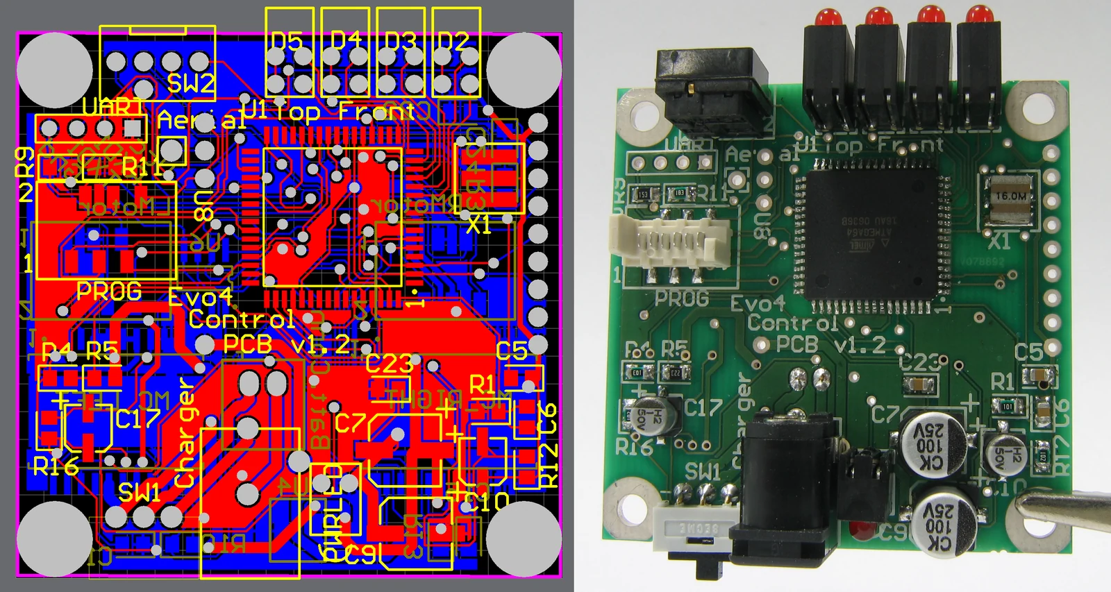
Photo: User Mike1024 / Wikimedia Commons · Public domain.
- SMT or Through-Hole: Start with the Component Function
- Mounting Density and Board-Space Trade-Offs
- Use pitch as a package-specific input
- Check the lead envelope against the finished hole
- Mechanical Loads, Connectors and Service Access
- Separate electrical contacts from structural attachment
- Keep through-hole where the installed interface needs it
- Reflow Versus Insertion and Soldering Operations
- Choose the sequence from component limits
- Inspection, Rework and Production-Volume Implications
- Specify coverage before comparing quotations
- Compare cost per accepted assembly
- Where Each Assembly Route Wins
- Where SMT wins
- Where through-hole wins
- A Build-Route Decision for Mixed-Technology Boards
- Final Recommendation: Release the Route with the Design
SMT or Through-Hole: Start with the Component Function
SMT and through-hole assembly describe how component terminations connect to the PCB. SMT terminations solder to surface lands. Soldered through-hole leads enter plated holes and form connections to the barrel and lands. Start with the function. Then select the exact manufacturer part number, because its package and processing limits determine which routes can deliver that function in the available board space.
A QFN controller requires its intended surface-mount land pattern; trimming a relay’s leads does not turn it into an SMT relay. A package substitution may change the pinout, thermal path, board outline and assembly tooling even when the replacement performs the same electrical function. Treat it as a design change.
Compare the routes against the same operating conditions, acceptance requirements and delivery scope:
| Decision Factor | SMT Route | Through-Hole Route | Mixed-Build Implication | Evidence to Request |
|---|---|---|---|---|
| Package availability | QFN, BGA, SOIC and chip packages attach to surface lands | Leaded connectors, relays and other specified packages require holes | Keep each required package in its suitable route | Exact BOM part numbers, package drawings and approved alternatives |
| Mechanical retention | Solder lands, anchor tabs and external supports carry loads | Leads, plated barrels and separate fixings contribute to attachment | Review the complete connector-to-enclosure load path | Mating-force data, support drawing and application load test |
| Placement density | Small packages reduce occupied area; escape routing still consumes space | Holes, annular lands and lead clearance constrain routing | Reserve space around necessary through-hole parts | Fabrication data, courtyards and assembled-height drawing |
| Soldering sequence | Paste deposition, placement and reflow suit compatible packages | Insertion precedes the selected soldering operation | Confirm thermal exposure and tool access at every step | Component processing limits and proposed operation sequence |
| Rework access | Hidden terminations may require controlled heating and package removal | Leads require solder removal without damaging plated barrels | Nearby parts can obstruct either method | Repair procedure, access drawing and replacement-part availability |
| Inspection coverage | Optical access varies by package; hidden joints need suitable assessment | Visible fillets do not expose every internal barrel feature | Define inspection and electrical coverage by joint type | Inspection plan, acceptance criteria and test coverage |
The OEM owns component selection, mechanical requirements and acceptance intent. The assembler proposes the sequence and identifies tooling or access constraints; the PCB fabricator confirms the finished geometry. Resolve conflicts before release. When a substitute changes the footprint, anchor arrangement or allowable heating, update the affected drawing and process requirements together so purchasing does not approve an electrically suitable part that the released build cannot accommodate.
Mounting Density and Board-Space Trade-Offs
SMT usually provides the more compact route when suitable surface-mount parts are available. Pitch alone is insufficient. A through-hole layout needs room for holes, copper lands and lead ends, while both routes must preserve routing channels, test access and the clearance needed to mate a connector without disturbing nearby components.
Mounting method does not fix connector pitch: Samtec’s surface-mount TSM and through-hole TSW families both use 2.54 mm pitch. Compare their complete footprints and retention features. Samtec TSM surface-mount terminal strip.
Use pitch as a package-specific input
Quad flat no-lead (QFN) and small outline no-lead (SON) packages use terminals on the package underside. The reference pitches in Table 1 of NXP AN1902, Rev. 9 (2021), are 0.40 mm, 0.50 mm, 0.65 mm, 0.80 mm and 1.00 mm. These are all entries in that table. The selected device’s drawing controls its geometry; the table is not a universal catalog of SMT pitches. NXP QFN/SON assembly guidelines.
For a compact controller with a suitable QFN/SON device, start the assembly review at 0.50 mm pitch. This is a density benchmark, not a rule to replace a satisfactory larger package. Review the peripheral terminals, exposed pad, paste release and hidden-joint inspection together. Moving to 0.40 mm needs a fresh review; it is not an automatic capability extension. Texas Instruments’ package guidance addresses both pitches with geometry-specific recommendations. Texas Instruments QFN and SON PCB attachment.
Check the lead envelope against the finished hole
A square lead does not fit a round hole according to its across-flat dimension alone. Samtec’s TSW example has a 0.635 mm square post on 2.54 mm pitch, while its recommended footprint shows a 1.02 mm nominal hole. Samtec TSW product geometry, recommended TSW footprint.
The nominal square diagonal is 0.635 × √2 = 0.898 mm. Subtracting it from 1.02 mm leaves approximately 0.122 mm across the diametral envelope, not on each side. That calculation explains the geometry; it does not establish production clearance. Check the maximum lead envelope against the minimum finished plated hole, including position tolerances and the exact connector variant. The drill tool diameter is a different manufacturing input.
Keep the assembly courtyard larger than the physical body where tools or mating parts need access. Eurocircuits distinguishes component boundaries, manufacturing courtyards and connector mating clearance in its component-clearance guidance. A smaller footprint is useful only if the resulting assembly can still be built, inspected and serviced.
Mechanical Loads, Connectors and Service Access
Through-hole attachment is often useful for connectors and leaded components that transmit force into the PCB, but it is not an automatic strength rating. Mechanical performance depends on the complete load path: connector housing, anchor features, solder joints, copper attachment, board supports and enclosure. An SMT connector with effective retention can outperform a poorly supported through-hole installation.
Separate electrical contacts from structural attachment
Specify how the interface is handled. Record mating and unmating force, cable pull direction, repeated service cycles and the distance between the load and the board support. Follow the force to the support. A mating-cycle rating describes a particular connector test; it does not qualify the assembled PCB against the bending moment from an unsupported cable, a different pulling direction or the equipment’s vibration environment.
Consider an illustrative perpendicular side load of 20 N applied 25 mm from the support. The bending moment is 20 N × 0.025 m = 0.50 N m. Moving the support closer reduces that moment even if the electrical termination remains unchanged. This is a load-path example, not a connector acceptance limit.
Soldered hold-downs, screws and chassis supports can carry forces that would otherwise reach signal joints. Samtec describes both SMT and through-hole weld tabs, plus screw-down attachment; it also distinguishes positioning features from structural retention. Samtec connector retention features.
Keep through-hole where the installed interface needs it
Retain a through-hole connector when its approved attachment, required lead geometry or repair arrangement depends on that construction. Review any proposed SMT alternative as a complete connector and support system. Matching current rating and pin count is insufficient.
Service access can favor either route. Visible through-hole leads can still be difficult to remove when large copper planes draw heat away from the joints. An accessible SMT connector with separate anchors may be straightforward to replace with suitable tooling, provided the technician can release the latch, grip the mating plug and support the PCB without loading neighboring components. Check the installed enclosure. Do not make the solder joints the handle.
Reflow Versus Insertion and Soldering Operations
SMT generally uses paste deposition, placement and reflow, while soldered through-hole assembly requires insertion followed by a compatible soldering operation. A through-hole package can sometimes join the reflow route through pin-in-paste processing. Its lead geometry, housing material and solder-volume requirements must support that choice.
Evaluate these four through-hole soldering candidates before fixing the board layout:
| Soldering option | Suitable starting situation | Constraint that changes the route |
|---|---|---|
| Wave soldering | Groups of accessible through-hole joints suited to a common pass | Exposed components, masking or pallet needs, and solder-side clearance |
| Selective soldering | Local through-hole joints on an otherwise populated assembly | Nozzle reach, nearby components, heating access and joint geometry |
| Manual soldering | Accessible joints in prototypes, repairs or limited secondary operations | Operator access, heat delivery, repeatability and inspection requirements |
| Pin-in-paste reflow | Reflow-compatible leaded parts designed for paste-based hole soldering | Body temperature limits, paste volume, insertion displacement and hole fill |
The table compares soldered joints. Press-fit uses a different connection mechanism and requires its own connector and plated-hole specification.
Choose the sequence from component limits
An SMT-reflow stage followed by through-hole insertion and localized soldering is a useful starting sequence for mixed boards. It is not mandatory. A component that cannot tolerate the planned reflow exposure belongs after that exposure, using an approved later attachment process.
Check the processing limits. An operating-temperature rating does not establish reflow compatibility. The planned sequence must account for allowable temperature and duration, repeated heating, moisture-sensitive packaging and connector plastics, while leaving the soldering tool a clear path after tall parts have been fitted. Record the exposure for each affected component.
Selective soldering applies flux, preheats the board and delivers solder locally through a nozzle. Its access requirements belong in the layout review. Eurocircuits selective-soldering explanation.
Pin-in-paste can consolidate operations, but inserting a lead can displace paste from the hole. Samtec’s interconnect handbook describes intrusive reflow and this geometry-dependent limitation. Samtec interconnect processing handbook. Approve the resulting joints on the actual board before removing a secondary operation from the production plan.
Inspection, Rework and Production-Volume Implications
SMT and through-hole routes need inspection matched to their joint geometry, and both need electrical verification matched to the product. Visible leads can improve access, but visibility alone does not prove joint integrity. Production quantity changes how setup and labor are distributed; it does not override the component’s mounting or thermal requirements.
Specify coverage before comparing quotations
For accessible SMT leads, automated optical inspection (AOI) can assess visible placement, orientation and solder features within its programmed coverage. A ball grid array (BGA) hides its connections. A QFN can hide the exposed-pad joint even when its perimeter is visible, so the acceptance plan must distinguish what optical inspection can assess from the hidden features assigned to X-ray assessment or electrical checks. Coverage must be explicit.
For through-hole joints, assess seating, lead condition and the specified solder features. Establish how required barrel fill will be evaluated. An external fillet does not reveal the entire connection inside the PCB. Where the purchase specification invokes an acceptance document, identify its revision and applicable product class so both quotations and inspection records refer to the same criteria.
Keep repair practical. Removing a through-hole connector can damage a plated barrel if solder remains attached; removing an SMT package can damage lands or nearby components if heat and lifting force are uncontrolled. Component access, thermal mass and the removal procedure matter more than the label on the route.
Compare cost per accepted assembly
SMT can distribute feeder setup, programming and stencil costs across repeat builds. Through-hole insertion may be manual, assisted or automated; the selected equipment and component packaging determine the labor content. Neither route has a universal batch-size crossover.
Match the quotation scope. Request the same released BOM, PCB revision, quantities, inspection coverage and functional tests, and separate one-time setup and fixtures from recurring material, placement, insertion, soldering, inspection and test charges. Include the secondary operations caused by a mixed build.
A useful comparison divides the total agreed batch cost by the number of accepted assemblies, with setup charges identified separately. Also identify responsibility for rework and scrap. A lower placement price can lose its advantage if inaccessible joints or unsuitable packaging create extra work. Repeated manual soldering is a reason to review the route, not evidence that SMT automatically wins.
Where Each Assembly Route Wins
SMT wins when the required packages and compact layout suit surface mounting. Through-hole wins where a leaded component or validated attachment justifies insertion and hole soldering. Apply three equal tests to both routes: package fit, mechanical fit and production fit. A strength in one category cannot cancel a failed requirement in another.
Where SMT wins
Package fit: A controller built around QFN ICs and chip passives requires SMT. Keep those packages when they meet the electrical and thermal requirements within the available area; changing to leaded substitutes would require another circuit and layout review.
Mechanical fit: A protected internal board with supported cables can benefit from compact SMT connectors and dedicated anchors. The enclosure and retention features must carry the specified loads.
Production fit: Repeat builds can benefit from automated placement when component packaging, pickup access and placement programs are suitable. Include the inspection and test work. A fast placement operation does not remove a hidden-joint inspection requirement.
Where through-hole wins
Package fit: A required leaded relay, transformer or connector establishes a through-hole need. Keep that construction when the specified electrical, thermal or mating requirements cannot be met by an acceptable SMT alternative within the design constraints.
Mechanical fit: A connector with a qualified through-hole attachment can be the better choice for an exposed service interface. Its PCB support and mating arrangement still need application-level validation.
Production fit: A few accessible leaded parts can justify controlled insertion and soldering. Price the whole change. Replacing them to eliminate an operation may introduce tooling, qualification or service costs greater than the work it removes.
A Build-Route Decision for Mixed-Technology Boards
Choose mixed technology when necessary SMT and through-hole components remain in the released design. Plan their sequence together. Before accepting the layout, check access, thermal limits and inspection coverage for the complete assembly, including soldered through-hole retention tabs on connectors whose signal contacts are SMT. Those tabs still require a compatible attachment operation.
| Project constraint | Starting decision | Release check |
|---|---|---|
| Compact controller with a selected 0.50 mm QFN/SON package | SMT for the controller circuitry | Confirm exact footprint, paste strategy and hidden-joint coverage |
| External connector with a validated through-hole attachment | Retain through-hole at that interface | Check load path, finished-hole fit and service access |
| Dense SMT circuitry plus required leaded power components | Mixed technology | Confirm insertion space and compatibility of subsequent soldering |
| Leaded connector qualified for paste-based reflow | Evaluate pin-in-paste within the mixed route | Verify thermal limits, solder volume and resulting hole fill |
| Required part cannot tolerate the planned oven exposure | Install it after that exposure | Confirm the later soldering method and access to every joint |
| Small pilot build with an intended repeat-production route | Preserve the production package choices where practical | Identify temporary manual operations and validate the intended repeat process |
Apply the decision at component level, then combine the results:
Released BOM + exact package drawings + mechanical load requirements
  -> SMT-compatible terminations and validated attachment: assign SMT
  -> Required soldered through-hole terminations: assign through-hole
  -> Both assignments on the same PCB: plan a mixed build
  -> Check thermal sequence, tool access, inspection and repair access
  -> Resolve conflicts in the design or process before production release
For example, an OEM controller can use SMT for its processor and small passives while retaining a leaded relay and through-hole cable interface. Review the relay’s processing limits, the connector support and the path to each later joint, because an otherwise acceptable component layout can leave a soldering nozzle or repair tool unable to reach the required connection. Resolve that conflict in the layout.
Freeze the resulting component list and operation sequence together. If a replacement connector changes the housing material, lead shape or anchor arrangement, repeat the affected route checks before accepting it as an alternate.
Frequently Asked Questions
SMT and through-hole assembly choices become clearer when the package, attachment and process are evaluated together. These answers address the decisions that most directly affect an OEM’s released build route.
Are through-hole parts always stronger than SMT parts?
No. Through-hole leads can contribute useful retention, but assembly strength also depends on the connector housing, solder joints, copper attachment, board support and applied load. An SMT part with suitable anchors and enclosure support can be the stronger installed solution. Validate the complete attachment under the intended service conditions.
When should a connector remain through-hole?
Keep a connector through-hole when its required package, approved attachment or service arrangement depends on that construction. Compare any SMT alternative using the same mating forces, cable loads, cycle requirements and board support. A matching pin count or electrical rating does not establish equivalent mechanical performance.
Can SMT and through-hole parts share one board?
Yes. A mixed-technology PCB combines both mounting methods, with each component assigned to a suitable operation. Define the sequence, thermal exposure, soldering access and inspection plan before release. Reflow followed by insertion and secondary soldering is one practical sequence; qualified pin-in-paste parts may allow a different arrangement.
Does SMT always reduce assembly cost?
No. SMT can reduce recurring placement work on repeat builds, but setup, component packaging, inspection, fixtures and secondary operations affect the result. Compare quotations for the same BOM revision, quantities and test coverage. Use cost per accepted assembly and identify one-time charges separately instead of comparing placement prices alone.
Which design files reveal the required assembly route?
The BOM with exact manufacturer part numbers, package drawings, PCB fabrication and drill data, placement file and assembly drawing together reveal the route. Mechanical drawings establish support and service constraints. Include component processing limits and inspection requirements so the assembler can evaluate whether the proposed sequence is workable.
Is there a universal minimum pitch for SMT?
No. Feasible pitch depends on the package, land pattern, PCB fabrication, paste deposition, placement and inspection process. For a compact QFN/SON controller, 0.50 mm is a useful design-review benchmark. It is not a universal minimum, and smaller pitches require review of the actual component and board construction.
Can through-hole components be soldered during reflow?
Yes, when the component and joint design support pin-in-paste reflow. Check the housing’s processing limits, lead and finished-hole geometry, paste volume and achieved hole fill. Through-hole mounting alone does not establish reflow compatibility, and a successful operation on one connector does not qualify every leaded component.
Which route is easier to repair?
The easier route is the one with accessible joints and a controlled removal process for the actual component. Through-hole removal can threaten plated barrels, while SMT removal can threaten lands and nearby parts. Assess tool access, copper thermal mass, replacement availability and the intended service procedure before choosing.
Final Recommendation: Release the Route with the Design
Use SMT for suitable compact circuitry, retain through-hole where the specified component or validated attachment requires it, and plan mixed technology when both needs remain. Release that decision with the BOM and drawings so purchasing, fabrication and assembly work from the same configuration.
Prepare the exact BOM, package information, fabrication and drill files, placement data and assembly drawing. Add connector load and support details, service access, component processing limits, batch quantities and the required inspection and test scope. Identify the parts that require a particular route and the alternatives that remain acceptable.
For a JASPER enquiry, use the PCB assembly services page with this package. Request a route review and a quotation that separates setup, recurring assembly work and any secondary operations. Agree the component choices, soldering sequence and acceptance coverage before the build is released.
Ready to Start Your Project?
Tell us about your membrane switch, keypad, or graphic overlay requirements. Our engineering team will review your specifications and provide a detailed quote.