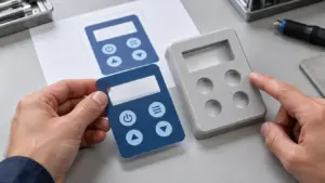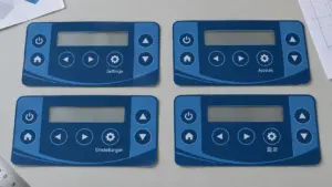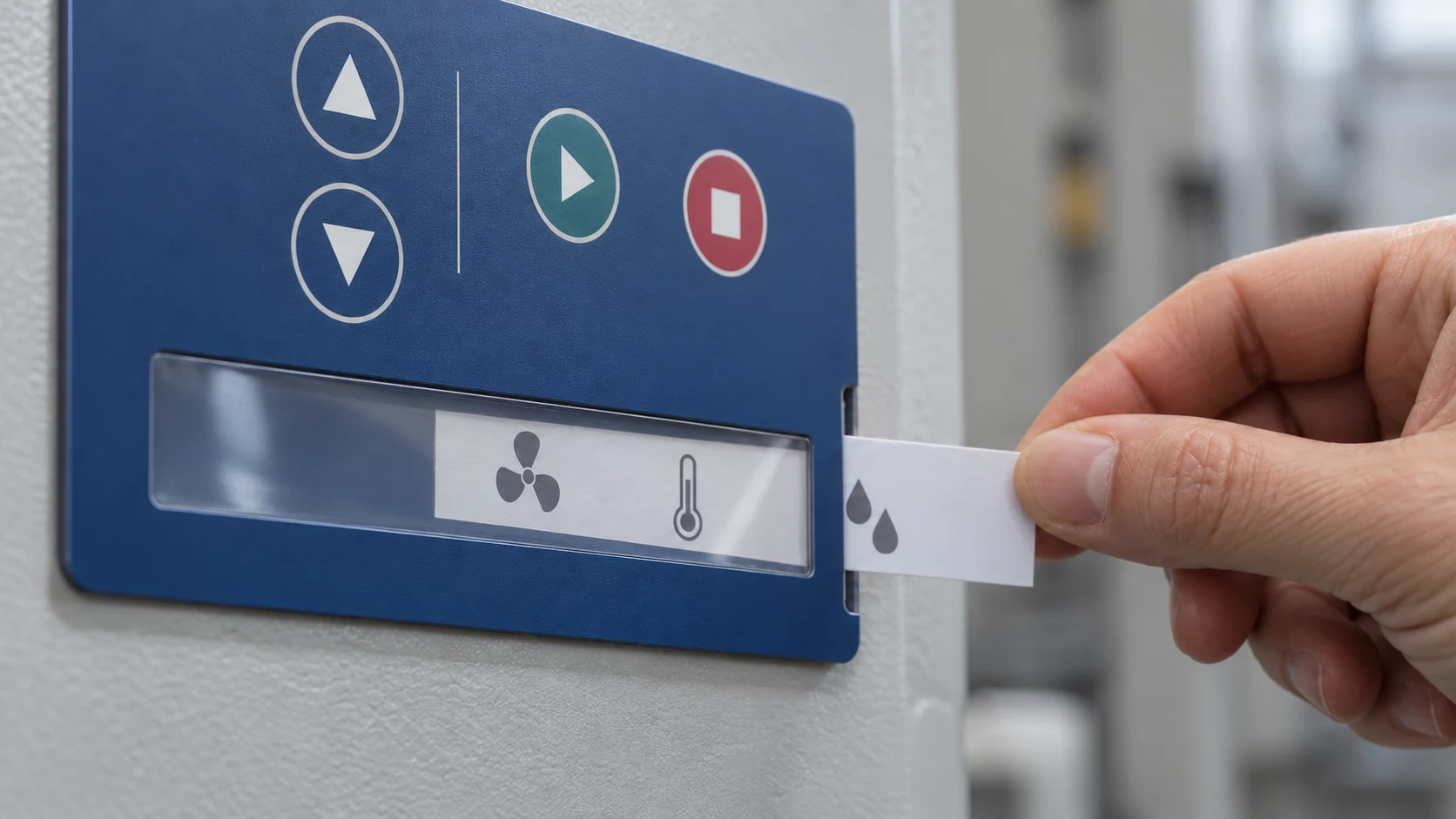
A graphic overlay insert pocket holds a removable printed card or strip behind a readable window. It lets an equipment name, operating legend, or parameter reference change while the surrounding overlay remains attached. The design needs an accessible replacement path, reliable retention, a defined readable area, and adhesive boundaries that keep the insert free to move. Replaceable does not mean sealed.
This guide addresses the label-holding feature, not a complete electrical switch. Because “membrane panel” can describe different supply scopes, specify whether the order covers an overlay, a complete membrane switch, or a panel assembled with mechanical parts.
- Define Why the Insert Must Be Replaceable
- Plan Access, Retention and Readable Area
- Coordinate Films, Adhesives and Openings
- Review Cleaning and Ingress Implications
- Complete the Insert Pocket Requirements Worksheet
- Confirm Replacement and Approval Procedures
- Load—Read—Remove—Maintain Check
- Separate Supplier and Customer Supply Boundaries
- Discuss a Replaceable-Legend Design
Define Why the Insert Must Be Replaceable
Start with what changes, who changes it, and when. A language strip selected during assembly has different access requirements from a parameter card replaced by a technician after installation. Distinguish factory-only insertion from field replacement before describing the feature as serviceable.
Consider permanent printing when the information does not need to change. Where it does, identify the permitted versions, replacement frequency, and consequences of installing the wrong card. Require operating legends to match the equipment configuration; changing the words does not change the underlying function. Refer proposed changes to safety-related instructions to the equipment owner’s approval process.
Illustrative example: An instrument has fixed controls but channel names assigned at installation. A removable channel-name strip could be considered, provided each name remains aligned with its intended control and the strip can be replaced in the installed enclosure.
Plan Access, Retention and Readable Area
Choose the access route in the assembled equipment, not only on a loose overlay. An edge-fed pocket needs space beyond its mouth for insertion and withdrawal. Rear access may require opening the enclosure. Access behind a removable bezel requires a defined disassembly and reassembly procedure. Check interference from adjacent panels, fasteners, cables, and the technician’s hands or gloves.
Define three separate geometries: the internal pocket, the visible window, and the insert’s print-safe area. Keep essential text inside the visible area throughout the permitted insert movement and registration variation. Check the smallest text, longest language version, viewing angle, and operating lighting on a representative assembly.
Specify how the insert reaches its final position, stays there, and can be retrieved. A stop, guide, pull tab, or access notch may be considered, but its suitability needs sample review. Do not rely on accidental friction as the only retention strategy. Check the intended orientation and handling conditions for drift or escape, and inspect exposed tabs for snagging.
Set clearance from the combined variation of insert size, pocket geometry, layer alignment, and installed cavity height. An insert that fits a loose sample may bind after mounting. Excess clearance also needs review because the card may shift outside its readable position. Do not adopt a universal gap without checking the actual stack.
Coordinate Films, Adhesives and Openings
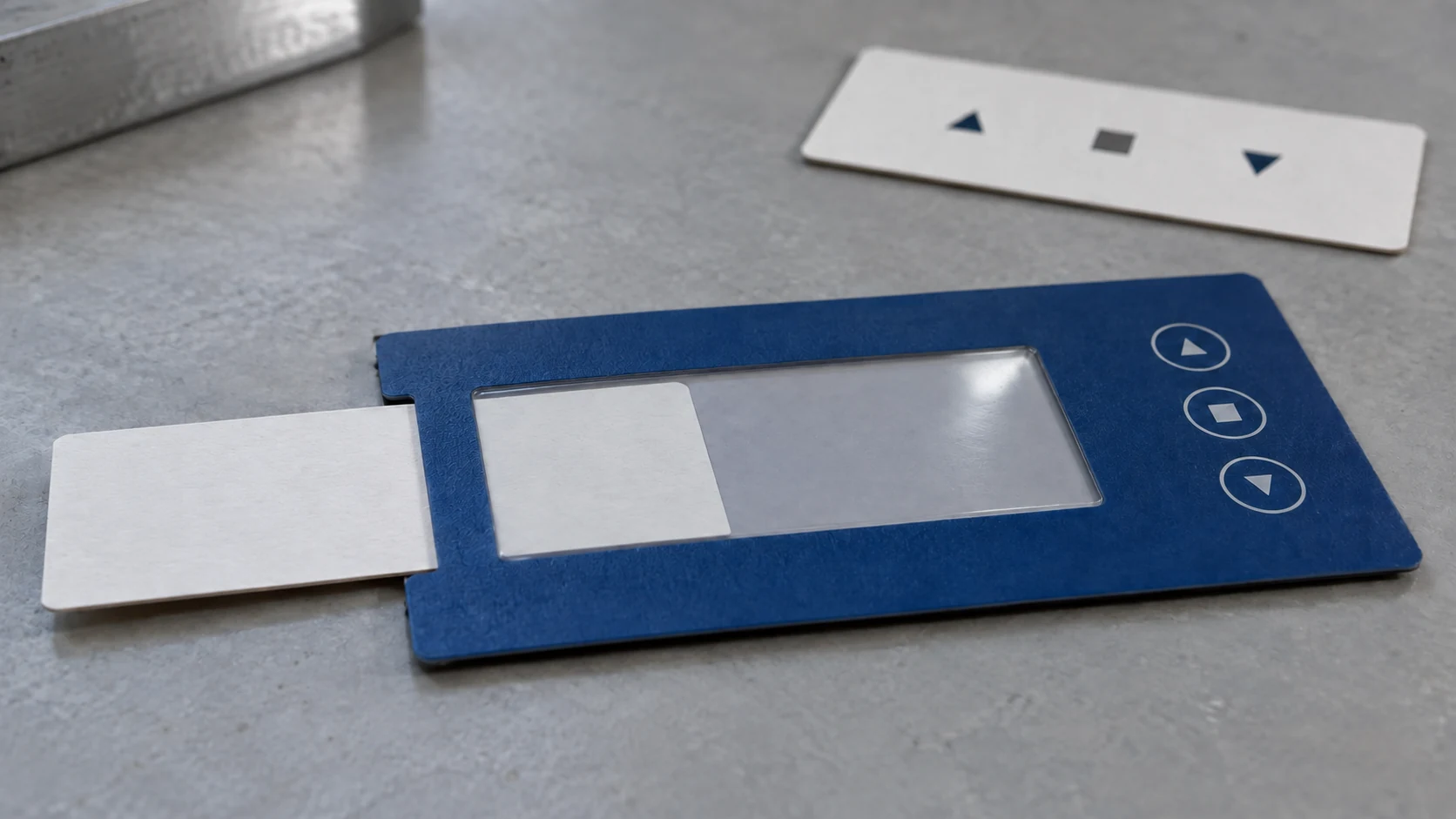
One construction to evaluate uses a transparent front film, a patterned spacer defining the pocket, a smooth backing layer, and a separate mounting adhesive. This is a design concept, not a required construction. Identify which parts form the pocket and which attach the assembly to the equipment.
On the drawing, distinguish the clear viewing region from physical cutouts. Show the insert travel envelope, entry mouth, stop, retrieval feature, bonded lands, and adhesive-free areas on each relevant face. The insert should not encounter exposed adhesive along its travel path or at its seated position. An opaque printed border is a visual mask, not a substitute for controlled adhesive geometry.
Evaluate the insert and pocket together. Specify finished insert thickness, including printing or lamination, rather than stock thickness alone. Check stiffness, curl, edge condition, surface friction, and possible ink transfer. Include proposed temperature and humidity conditions in the fit review. Verify usable cavity height after assembly rather than treating nominal adhesive thickness as the available gap.
Select bonding materials against the actual mating surfaces, assembly process, and environment. Review whether the remaining bonded area supports insertion and withdrawal without lifting the pocket edges. Keep the pocket outside moving key areas unless the combined structure is specifically designed and tested for key operation. Do not use a working label pocket as evidence of switch performance.
Review Cleaning and Ingress Implications
A clear front window does not close the insert opening. Identify whether that opening communicates with the enclosure interior or belongs to a separate pocket outside the equipment’s protective boundary. Define two acceptance questions: must the insert remain dry and readable, and must the enclosure prevent harmful ingress? Passing one does not establish the other.
Record the cleaner, concentration, application method, contact time, drying procedure, and frequency. Evaluate the assembled pocket, insert, printing, and exposed edges under that routine. Look for trapped liquid, clouding, ink transfer, sticking, curling, and bond lifting.
Any ingress-protection claim must relate to the defined enclosure configuration and applicable test conditions, not to film or adhesive alone. Include service opening and reclosure in the validation plan where they can affect protection. A water-resistant insert material is not a substitute for a validated enclosure seal. Where the proposed cleaning routine cannot be supported, reconsider the access location or labeling approach.
Complete the Insert Pocket Requirements Worksheet
Use this blank worksheet to prepare a custom overlay pocket design review. Reference controlled drawings and procedures rather than filling gaps with assumed values.
| Requirement | Information to define | Project entry |
|---|---|---|
| Purpose and content | What changes; permitted versions; configuration match | |
| Service model | Factory insertion or field replacement; responsible person | |
| Access | Entry direction; installed clearance; permitted tools or disassembly | |
| Insert specification | Finished dimensions, thickness range, material, print process | |
| Pocket geometry | Cavity dimensions, installed height, guides, stop, retrieval feature | |
| Readability | Window, print-safe area, allowed movement, viewing conditions | |
| Retention | Orientation, handling exposure, allowed displacement | |
| Adhesive layout | Bonded lands, adhesive-free path, mating surfaces | |
| Environment and cleaning | Temperature, humidity, cleaner, exposure and drying routine | |
| Acceptance | Insertion/removal method, effort limits, replacement cycles, defect criteria | |
| Documentation | Part and artwork revisions, approval owner, replacement instructions |
Confirm Replacement and Approval Procedures
Approve a representative installed assembly with the intended insert stock and artwork. Define acceptance limits, sample quantity, conditioning, replacement cycles, and measurement methods before testing. Where effort is measured, record the insertion direction, speed, fixture, and tool so results remain comparable. These are project-defined requirements, not universal pocket specifications.
Load—Read—Remove—Maintain Check
| Stage | Check on the assembled sample | Hold approval when |
|---|---|---|
| Load | Confirm the correct card and orientation. Insert through the intended access route using the approved handling method. Check seating, alignment, and neighboring features. | The card buckles, catches adhesive, requires unplanned prying, lifts an edge, or cannot reach its stop. |
| Read | Inspect essential text at permitted card positions, viewing angles, and lighting. Check alignment to controls and retention under the agreed handling conditions. | Text is obscured, associates with the wrong control, becomes unreadable, or the insert drifts beyond its allowed position. |
| Remove | Retrieve the card using the intended tab, notch, or tool. Inspect the insert, pocket mouth, window, and bonded edges. | Removal requires peeling a permanent bond, damages the window, tears the card, or leaves adhesive or ink contamination. |
| Maintain | Apply the specified cleaning and replacement sequence. Reinspect fit, readability, retention, edges, and any affected enclosure closure. Record the installed revision. | Liquid remains where prohibited, damage accumulates, the card sticks, retention changes, or the correct configuration cannot be verified. |
A successful first insertion is not approval for repeated replacement. Repeat the relevant checks after the agreed conditioning and service cycles. Record the sample identity, insert specification, assembly configuration, observations, and approval decision. Investigate a failed check before changing the handling instructions to accommodate a defective fit.
Separate Supplier and Customer Supply Boundaries
Agree the scope in the quotation and drawing package. An overlay order should not be assumed to include a completed pocket, printed cards, mounting, or field replacement service.
| Deliverable | Supplier scope to agree | Customer/OEM scope to agree |
|---|---|---|
| Pocket components | Films, spacer, backing, adhesive conversion, or assembled pocket | Enclosure interfaces, access space, mechanical constraints |
| Inserts | Blank or printed cards, material, cutting, packing, spare quantities | Approved content, languages, configuration mapping; customer-supplied stock where selected |
| Initial assembly | Preloading, mounting, orientation and inspection, where included | Work performed during equipment assembly and its acceptance |
| Verification | Component checks and records included in the order | Installed-equipment validation and final approval ownership |
| Replacement support | Repeat-order specification and replacement parts, where included | Authorized service procedure, stock control, revision records |
Assign an owner to every operation. Identify customer-supplied inserts separately and verify them against the pocket specification. Record who approves substitutions to card stock, printing, dimensions, or assembly materials.
Frequently Asked Questions
Can a replaceable legend be backlit?
Treat this as a separate optical review. Evaluate the actual insert, printing, window, light source, and permitted movement together. Check lit and unlit readability, alignment, and unwanted light leakage. Acceptance of an unlit pocket does not establish acceptable backlighting.
Can the customer print replacement inserts?
Define an approved printing route before relying on local printing. Control the stock, finished thickness, print scale, artwork revision, cutting, and print durability. Qualify representative customer-produced cards in the pocket; a file that looks correct on screen does not establish fit or service performance.
Discuss a Replaceable-Legend Design
Planning a changeable label area within custom graphic overlays for OEM panels? Describe what changes, who replaces it, the available access, and the cleaning environment. Start with a requirements description even when materials and production drawings are not yet selected. Identify the components and service operations you need included so the supply scope can be discussed explicitly.
Ready to Start Your Project?
Tell us about your membrane switch, keypad, or graphic overlay requirements. Our engineering team will review your specifications and provide a detailed quote.